Installation Instructions Stationary Weighpad_ELWC - WIM
Installation Instructions Stationary Weighpad_ELWC - WIM
Installation Instructions Stationary Weighpad_ELWC - WIM

Create successful ePaper yourself
Turn your PDF publications into a flip-book with our unique Google optimized e-Paper software.
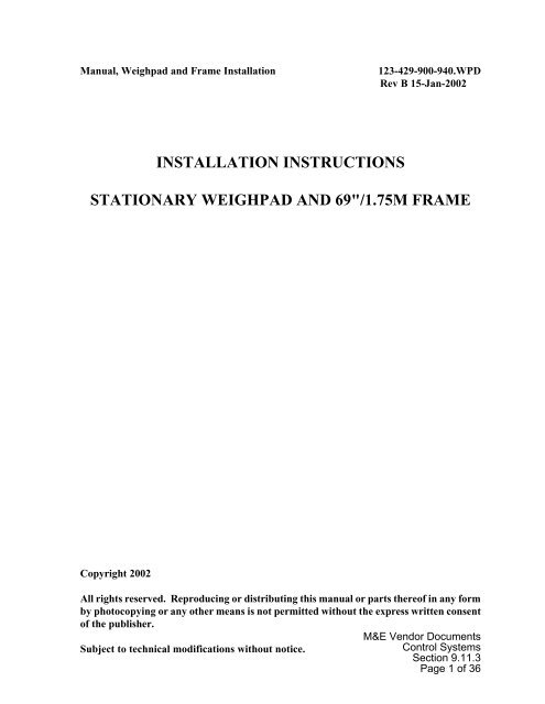
Manual, <strong>Weighpad</strong> and Frame <strong>Installation</strong> 123-429-900-940.WPD<br />
Rev B 15-Jan-2002<br />
INSTALLATION INSTRUCTIONS<br />
STATIONARY WEIGHPAD AND 69"/1.75M FRAME<br />
Copyright 2002<br />
All rights reserved. Reproducing or distributing this manual or parts thereof in any form<br />
by photocopying or any other means is not permitted without the express written consent<br />
of the publisher.<br />
Subject to technical modifications without notice.<br />
M&E Vendor Documents<br />
Control Systems<br />
Section 9.11.3<br />
Page 1 of 36
M&E Vendor Documents<br />
Control Systems<br />
Section 9.11.3<br />
Page 2 of 36
TABLE OF CONTENTS<br />
1. GENERAL INFORMATION ..................................... 1<br />
2. PREPARATION .............................................. 4<br />
2.1 Construction Tools Required for <strong>Installation</strong> ................ 4<br />
2.2 <strong>Installation</strong> Materials .................................... 6<br />
2.3 Foundation Frame Parts Breakdown ....................... 7<br />
3. INSTALLATION PROCEDURE .................................. 9<br />
4. APPENDIX E–Bond G–100 Epoxy .............................. 25<br />
5. APPENDIX SITE SURVEY FORM ............................... 31<br />
M&E Vendor Documents<br />
Control Systems<br />
Section 9.11.3<br />
Page 3 of 36
M&E Vendor Documents<br />
Control Systems<br />
Section 9.11.3<br />
Page 4 of 36
1. GENERAL INFORMATION<br />
The stationary weighpads of the dynamic axle load scales are subject to extreme strain<br />
in normal traffic such as high, abrupt load changes, temperature fluctuations, water,<br />
etc.<br />
To run the system for a reasonable period without failures, it is important to install the<br />
foundation frames and weighpads very carefully in accordance with these instructions.<br />
It is recommended that the first installation always be done under the supervision of a<br />
specialist.<br />
<strong>Weighpad</strong> foundation frames can be installed into any normal roadway surface, asphalt<br />
or concrete, if the compacted upper layer of the pavement is more than 6" (15 cm)<br />
thick. The frame, including the weighpad embedded in it, has a total height of 2¼” (6<br />
cm) in the support area. <strong>Installation</strong> is made into the wearing course without special<br />
foundation. If the compacted pavement is less than 6" (15 cm) thick, a foundation<br />
socket of concrete has to be built under the frame, just as wide as the frame. The<br />
anchors are inserted into bores of 1" (2.5 cm) diameter and reach down into the base<br />
course approximately 8" (20 cm). In case of reinforced concrete pavement, consult<br />
the construction engineer before cutting.<br />
The following aspects have to be observed when choosing the installation site for the<br />
weighpads:<br />
1<br />
M&E Vendor Documents<br />
Control Systems<br />
Section 9.11.3<br />
Page 5 of 36
It is possible for water to penetrate into the frame or under installed weighpads.<br />
This leads to false axle load measurements, especially in the winter when water<br />
freezes under the weighpads. Therefore, it is necessary to install a drain pipe<br />
at the lowest point of the frame recess. The drain should be 2"–4" (5 cm - 10<br />
cm) diameter and sloping into a french drain, water shaft or culvert.<br />
Figure 1 - Drainage Styles<br />
The roadway is part of the <strong>WIM</strong> system and therefore must be as flat and<br />
uniform as possible for approximately 200' (60 M) before and 50' (15 M) after<br />
the weighpad. For increased accuracy requirements, evenness must meet<br />
ASTM1318 specifications, at a minimum must not exceed 1/10" (0.25 cm) in 13'<br />
(4 M).<br />
ASTM 1318 requires a stretch of 150' before and 150' after the scale to be level<br />
within the evenness tolerance. IRD-PAT Traffic only requires a 50' stretch after<br />
the scale, but 200' before the scale to be level.<br />
Vehicles to be measured must be able to pass over the weighpads without<br />
accelerating or braking.<br />
The entire measuring distance must be straight, with no curves or grades. The<br />
longitudinal slope must not exceed 3% for statistical traffic data registration or<br />
1% for weighstations. A transverse slop of approximately 1% at weighstations<br />
is desirable to avoid hydroplaning.<br />
Wheel grooves existing in the measuring area must be removed.<br />
2<br />
M&E Vendor Documents<br />
Control Systems<br />
Section 9.11.3<br />
Page 6 of 36
Trucks, when passing the measuring spot, must not appear to bounce.<br />
Profilograph records do not always show the long wave repeating unevenness<br />
which can create high dynamic axle weight variations.<br />
In case of doubt, contact IRD-PAT Traffic for verification. IRD-PAT Traffic<br />
reserves the right to refuse a site if the above conditions are not met.<br />
A Site Survey Sheet (form number 123-422-000-630, see the appendix) has to be<br />
completed, and the site conditions have to be accepted by both IRD-PAT Traffic and the user.<br />
3<br />
M&E Vendor Documents<br />
Control Systems<br />
Section 9.11.3<br />
Page 7 of 36
2. PREPARATION<br />
To avoid unnecessary waiting periods during installation it is important to compile and<br />
check all construction tools listed below before beginning. This is particularly important<br />
if there is a time limit for blocking the road.<br />
2.1 Construction Tools Required for <strong>Installation</strong><br />
Heavy Equipment:<br />
Item Quantity Description<br />
1 1 Air Compressor, 160CFM minimum.<br />
2 1 Air driven Rock Drill, with 1" diameter 20" long bit.<br />
3 1 Air driven Hammer (typically 60 lbs.), with 1" chisel and<br />
3" - 4" spade bits, and appropriate safety equipment.<br />
4 1 Air blow-wand.<br />
5 1 Concrete saw (recommend 11 or more horsepower) with<br />
diamond blades.<br />
6 1 Ditch digger or Backhoe for conduit trenches.<br />
7 1 AC Generator (recommend 4KW or larger) and 150'<br />
extension cables.<br />
8 1 Water for concrete cutting and washdown.<br />
9 1 If installing below 50 °F (10 °C), a gas space heater or<br />
torpedo heater and two sheets 4'x8' plywood.<br />
10 1 set Conduit cutting and threading tools, up to the maximum<br />
size of conduit specified.<br />
4<br />
M&E Vendor Documents<br />
Control Systems<br />
Section 9.11.3<br />
Page 8 of 36
Power Tools:<br />
Item Quantity Description<br />
1 1 Industrial 3/4" drill, approximately 200 RPM, with heavyduty<br />
mixer attachment 16-20" long.<br />
2 1 Angle Grinder with cutoff wheels and grinding wheels for<br />
steel and rocks, with safety glasses.<br />
3 1 Industrial vacuum cleaner.<br />
4 1 Propane gas burner, for drying pavement.<br />
5 1 Air or electric impact wrench with 3/4" socket.<br />
6 1 Torque wrench with 3/4" socket, rated to at least 100<br />
Ft–Lb.<br />
7 1 Hand tools and accessories consisting of:<br />
Tin snips<br />
Hack saw<br />
2-5 lb hammer<br />
Caulk guns<br />
8 1 Pick, shovel, broom, spade, trowel, and wheel barrow.<br />
9 3 each 2" and 4" plastic putty knifes, wire bristle brush.<br />
These items will be destroyed in the installation process<br />
due to drying epoxy.<br />
10 1 Chalk, marking paint, and string<br />
11 2 4' Bubble level.<br />
12 1 each 10-15' straight edge, measuring wedge, and 100' tape<br />
measure.<br />
13 per<br />
person<br />
Latex gloves, safety glasses, and protective clothing.<br />
14 1 set Frame installation / leveling aids, two per frame.<br />
Reusable, but recommend four per installation to<br />
increase speed.<br />
15 1 Fish tape, recommend 100'.<br />
5<br />
M&E Vendor Documents<br />
Control Systems<br />
Section 9.11.3<br />
Page 9 of 36
2.2 <strong>Installation</strong> Materials<br />
Item Quantity Description<br />
1 1 per<br />
frame<br />
2 Per site<br />
plans<br />
3 Per site<br />
plans<br />
4 Per site<br />
plans<br />
Approximately 7 gallons of two-part filled epoxy.<br />
Recommended brand is “E–Bond G–100,” shipped in<br />
2.7 gallon cans.<br />
Galvanized steel conduit as per site plan, for cables and<br />
drain water. If the conduit has to be installed in the road<br />
surface, choose a diameter of 1-½” or 2" for crush<br />
strength. If there is a possibility of installing the conduit<br />
below the frame and road surface, choose a diameter of<br />
2" to 3", for maximum ease of cable installation and to<br />
avoid future maintenance issues. For the drain water,<br />
PVC pipe can be used if crush strength is not a concern.<br />
Elbows, galvanized, diameter matching item #2.<br />
Conduit grounding bushings for weighpad frames and all<br />
junction boxes.<br />
5 #8 solid copper ground wire.<br />
6 Per site<br />
plans<br />
7 80lb per<br />
frame<br />
Pullboxes<br />
Portland cement, without rocks.<br />
8 Marking tape (length depending on ditch length). The<br />
plastic tape with red and white stripes is inserted before<br />
closing the ditches. It is used as a warning in the event<br />
of future earthmoving operations.<br />
9 3 per<br />
frame<br />
10 1 oz. per<br />
frame<br />
Caulk tubes of silicone sealer.<br />
Anti-seize grease<br />
11 1 Roll of 2" duct tape<br />
12 4 Parts to construct frame leveling aids. These consist of:<br />
3' section of 2x4<br />
2 6" sections of ½-20 threaded rod<br />
4 ½-20 nuts<br />
4 ½ flat washers<br />
M&E Vendor Documents<br />
6<br />
Control Systems<br />
Section 9.11.3<br />
Page 10 of 36
13 1 Spray paint (epoxy paint) with primer, black.<br />
14 1' per<br />
frame<br />
1" flexible PVC conduit or “smurftube,” if loop lead-in<br />
cables are routed through the weighpad conduits.<br />
2.3 Foundation Frame Parts Breakdown<br />
Figure 2 - Frame Illustrated Parts Assembled<br />
7<br />
M&E Vendor Documents<br />
Control Systems<br />
Section 9.11.3<br />
Page 11 of 36
Figure 3 - Frame Illustrated Parts Breakdown<br />
8<br />
M&E Vendor Documents<br />
Control Systems<br />
Section 9.11.3<br />
Page 12 of 36
3. INSTALLATION PROCEDURE<br />
The following jobs have to be performed:<br />
! Ensure sufficient protection of the job site.<br />
! With chalk and marking paint, mark the exact installation points for frames and<br />
induction loops as well as for drain pipes and cable conduits. See site-specific<br />
diagrams provided by IRD-PAT Traffic.<br />
If the conduits and drains were precast into the concrete slab, verify placement<br />
accurately. The drains must be centered under the weighpad in the traffic<br />
direction.<br />
Observe squareness to the traffic direction.<br />
Figure 4 - Laying out Site 123-429-901-120.JPG<br />
9<br />
M&E Vendor Documents<br />
Control Systems<br />
Section 9.11.3<br />
Page 13 of 36
! Cut the marked frame border 2-¼” (6 cm) deep with a concrete saw. Do not<br />
crosscut over corners to avoid the risk of future breaking. Then cut the surface<br />
to be broken out for the frame into pieces as per drawing. Do not crosscut over<br />
the edges. Then cut the excavation for drain water pipe and cable conduit to 4"<br />
(10 cm) deep.<br />
In case of reinforced concrete, consult the construction engineer before cutting.<br />
Figure 5 - Frame Recess Cutting Diagram<br />
10<br />
M&E Vendor Documents<br />
Control Systems<br />
Section 9.11.3<br />
Page 14 of 36
Figure 6 - Cutting Frame Recess 123-429-900-950.JPG<br />
! Cut induction loops. See site-specific diagrams provided by IRD-PAT Traffic.<br />
11<br />
M&E Vendor Documents<br />
Control Systems<br />
Section 9.11.3<br />
Page 15 of 36
! Excavate frame recess with a compressed air hammer.<br />
Figure 7 - Excavated Recess<br />
123-429-901-130.JPG<br />
! Cover inside of frames and bolts with duct tape to prevent excess epoxy from<br />
adhering to the frame. Leave the anchor holes uncovered. This will save<br />
significant time in cleaning the frame and bolts from overflow epoxy.<br />
! Attach frame leveling aids to frames. These are constructed from 2x4 stock.<br />
Figure 8 - Frame Leveling Aid<br />
12<br />
M&E Vendor Documents<br />
Control Systems<br />
Section 9.11.3<br />
Page 16 of 36
! Check depth of the cutout by inserting frame into recess. Mark breakouts with<br />
marking paint for the cable tube welded to frame, and anchors holes.<br />
Figure 9 - Frame in Recess 123-429-900-960.jpg<br />
13<br />
M&E Vendor Documents<br />
Control Systems<br />
Section 9.11.3<br />
Page 17 of 36
! Take the frame out of recess and drill anchor holes. Start vertically to about ½”<br />
depth, then slowly turn to a 45° angle.<br />
Figure 10 - Drilling Frame Anchor Holes123-429-900-970.jpg<br />
! Clean frame recess and anchor holes with compressed air. Dry with a propane<br />
gas burner if necessary. The surface must be dry and clean. Epoxy will only<br />
adhere to dry and clean rock, concrete, or asphalt surface.<br />
Figure 11 - Drying Recess with Propane123-429-901-110.jpg<br />
14<br />
M&E Vendor Documents<br />
Control Systems<br />
Section 9.11.3<br />
Page 18 of 36
! For inline weighpads that are inline or in adjacent lanes, install a 2" conduit or<br />
appropriate length between the weighpads.<br />
Figure 12 - 2" In-line Cable and Drainage Conduit<br />
! Install the drain and cable conduit, if not already stubbed-in as with new<br />
concrete installations.<br />
! Place frame in recess. Adjust the height of the frame so that studs are 1/16" or<br />
less below road surface. All studs must be below the road surface, but not more<br />
than 3/32". Tighten lower nuts against leveling aid, and verify frame height.<br />
15<br />
M&E Vendor Documents<br />
Control Systems<br />
Section 9.11.3<br />
Page 19 of 36
! Mix the portland cement, somewhat dry, and build cement walls. The walls are<br />
only used to keep epoxy in place after pouring. The frame can be used for<br />
leveling.<br />
Figure 13 - Creating Cement Walls 123-429-900-980.jpg<br />
! Remove excessive concrete and other loose debris in the bearing area and<br />
clean the bearing area with compressed air and/or vacuum cleaner. This step<br />
is very important as any debris will reduce the bonding effect.<br />
! Check the bottom of the frame. Remove any debris which might adhere to the<br />
bituminous coating.<br />
! Seal off ends of cable and drain conduits with duct tape.<br />
! Attach #8 solid copper bonding wire(s) to the frame.<br />
! Set frame close to the recess.<br />
! When working with epoxy resin, wear appropriate protective clothing. Note the<br />
following important points:<br />
” It is important to remember that water is an enemy of all epoxy resin<br />
adhesives. Therefore, the installation and in particular the support areas<br />
of the frames and anchor holes must be dry.<br />
16<br />
M&E Vendor Documents<br />
Control Systems<br />
Section 9.11.3<br />
Page 20 of 36
” Do not use epoxy remaining on the edges of the bottom of the container.<br />
This has not been mixed thoroughly with the hardener, and therefore will<br />
not set properly.<br />
” At temperatures below 50°F, preheat the epoxy to about 80°F. At<br />
temperatures above 80°F, store the epoxy and hardener in a room with<br />
temperature below 75°F. For installations in extreme temperature<br />
conditions, contact IRD-PAT Traffic for instructions.<br />
” Expect a working time of approximately three to five minutes above 70°F,<br />
ten minutes between 60 and 70°F, and 15 or more minutes below 60°F.<br />
” For further information on epoxy, see “Processing <strong>Instructions</strong>” in the<br />
E–Bond G–100 appendix.<br />
! Without adding the hardener, premix epoxy in sufficient quantity (three buckets<br />
per frame). The filled epoxy settles significantly during shipping.<br />
! Add the hardener, and mix another two to three minutes, especially at the<br />
edges. Processing time and setting time vary with temperature.<br />
! Pour the epoxy into anchor holes first, then into the bearing area outside the<br />
cement retaining wall. The level should come up to the indentation formed by<br />
the frame on the cement wall.<br />
Figure 14 - Pouring Epoxy 123-429-900-990.jpg<br />
17<br />
M&E Vendor Documents<br />
Control Systems<br />
Section 9.11.3<br />
Page 21 of 36
! Apply the epoxy with a wire brush to vertical edges of the frame recess to obtain<br />
maximum bonding and eliminate air pockets. Epoxy will not adhere otherwise<br />
and can cause early loosening of the frame.<br />
! Immediately afterwards press the frame into the epoxy and insert the anchors.<br />
Remove epoxy overflowing into the frame immediately. Make sure the frame<br />
rests completely on epoxy. If pockets of air are suspected underneath the<br />
frame, immediately lift frame and fill with more epoxy.<br />
The epoxy may not fill up to the road surface. It must completely fill up to the<br />
top level of the steel frame.<br />
Figure 15 - Removing Excess Epoxy 123-429-901-000.jpg<br />
18<br />
M&E Vendor Documents<br />
Control Systems<br />
Section 9.11.3<br />
Page 22 of 36
! Insert anchors down as far as possible. They must not protrude into the<br />
weighpad area. Weigh down the frame with 50-100lb objects until epoxy has<br />
set.<br />
Continue to remove epoxy overflowing into the frame, to make later cleanup<br />
easier.<br />
Figure 16 - Driving in Anchors 123-429-901-010.jpg<br />
! Install other inline frames one after another (as described before), making sure<br />
there is no gap between frames.<br />
19<br />
M&E Vendor Documents<br />
Control Systems<br />
Section 9.11.3<br />
Page 23 of 36
! When epoxy has set after approximately 30-60 minutes (refer to E–Bond epoxy<br />
curing chart in the appendix), remove leveling aids, remove duct tape, and clean<br />
frames. Grinding may be necessary to remove excess epoxy.<br />
Do not use the grinder to clean epoxy on or near the mounting bolts.<br />
Figure 17 - Grinding Frame Clean 123-429-901-020.jpg<br />
! Make electrical ground connections with #8 bare copper wire UNDERNEATH<br />
the frame at the provided ¼” bolts between frame and cable conduit.<br />
20<br />
M&E Vendor Documents<br />
Control Systems<br />
Section 9.11.3<br />
Page 24 of 36
! At each mounting stud, measure necessary shim thickness. This can be<br />
measured by placing a straightedge in the direction of traffic, measuring the<br />
depth of the frame, and subtracting 1-¼”.<br />
Figure 18 - Measuring Shim Height 123-429-901-140.jpg<br />
Figure 19 - 3/32" Required Shim Thickness 123-429-901-150.jpg<br />
21<br />
M&E Vendor Documents<br />
Control Systems<br />
Section 9.11.3<br />
Page 25 of 36
! Figure out the necessary shim thickness across each side of the frame, in terms<br />
of 1/16" and 1/32" shims. Exact level is important in the wheel track.<br />
If the frame was mounted in an oblique position, cut the shims to corresponding<br />
lengths to insert them in a staggered form. Shims may only be cut in the center<br />
between two bolts, not at the bolts. Not more than one shim can be cut between<br />
the same two bolts.<br />
In some cases, the thickness change across the length of the frame may be<br />
more than can be adjusted only cutting one shim between bolts. Use an<br />
adjusted average in this case.<br />
For example:<br />
5/32" 1/32" 3/32" 2/32" 3/32" 5/32"<br />
Would become:<br />
4/32" 2/32" 3/32" 2/32" 3/32" 5/32"<br />
Which would result in the shims:<br />
1/16" 1/16" 1/16" 1/16" 1/16" 1/16"<br />
1/16" 1/32" 1/32" 1/32"<br />
1/16"<br />
When cutting shims, note that the shim near the cable conduit must have an<br />
extra corner cutout to allow the cable clearance.<br />
! Insert shims into the frame to compensate for the difference if height as<br />
calculated.<br />
! Insert ¼" support rails into frames over shims.<br />
! IMPORTANT NOTICE: Be sure not to damage the bottom side of the weighpad.<br />
Keep the weighpad in its shipping case as long as possible, and immediately set<br />
it into the frame after unpacking it. NEVER LAY THE WEIGHPAD ON THE<br />
ROAD ON ITS BOTTOM SIDE. NEVER PULL OR TWIST THE CABLE, AND<br />
AVOID LOOPS.<br />
22<br />
M&E Vendor Documents<br />
Control Systems<br />
Section 9.11.3<br />
Page 26 of 36
! Set weighpad onto two wooden pieces with its upper side close by the frame<br />
and carefully push connecting cable through the cable tube.<br />
Figure 20 - Installing <strong>Weighpad</strong> 123-429-901-030.jpg<br />
! Insert one securing rail shim on the side away from the weighpad. The shim<br />
should lay towards the outside of the frame.<br />
! Insert the weighpad centrally into the frame with the cable end first, then lower<br />
the other end down to 1" and let go. Ensure the weighpad is against, but not on,<br />
the securing rail shim. Insert one securing rail shim on the other side of the<br />
weighpad.<br />
! Place silicone in the cable entry conduit, and around where the cable comes out<br />
of the weighpad. This is to keep debris out, not to prevent entry of water.<br />
! Grease each ½” bolt in the frame as well as the silicone rubber strip on the<br />
securing rails with anti-seize.<br />
23<br />
M&E Vendor Documents<br />
Control Systems<br />
Section 9.11.3<br />
Page 27 of 36
! Insert the securing rails and attach with locking nuts and spring washers<br />
provided. Run the nuts down snug, using a staggered pattern. This will ensure<br />
the weighpad is centered in the frame. Then tighten the nuts with a torque<br />
wrench to 85 Ft-Lb torque, again in a staggered pattern.<br />
Figure 21 - Tightening Securing Rails 123-429-901-040.jpg<br />
! Verify that weighpad corresponds to roadway level over entire width by means<br />
of a straight edge. If weighpad is lower by more than 1/32", adjust shims<br />
accordingly and check again. Allowable tolerance is ±1/32".<br />
! Install other weighpads in the same manner. Before inserting the last weighpad,<br />
pull connecting cable through the conduit. Make sure the cable is not subject<br />
to torsion, does not form any loops, and is not bent. Leave slack underneath the<br />
frame of about 2', to allow for maintenance removal of the weighpad.<br />
! Carefully cut off protruding red silicone rubber from securing rails. Do not cut<br />
into the weighpad rubber, or the connecting cable.<br />
! Seal with silicone the joints between weighpad, frame, and securing rails on the<br />
short ends. Also, fill each recessed nut hole with silicone. This is to keep<br />
debris out, not to prevent entry of water.<br />
! Open the roadway to traffic after the epoxy, silicone, and loop sealant have<br />
cured sufficiently. See the appropriate data sheets for cure time charts. This<br />
is usually one to five hours, depending on temperature.<br />
24<br />
M&E Vendor Documents<br />
Control Systems<br />
Section 9.11.3<br />
Page 28 of 36
4. APPENDIX E–Bond G–100 Epoxy<br />
25<br />
Ebond G100 Page1.jpg<br />
M&E Vendor Documents<br />
Control Systems<br />
Section 9.11.3<br />
Page 29 of 36
26<br />
Ebond G100 Page2.jpg<br />
M&E Vendor Documents<br />
Control Systems<br />
Section 9.11.3<br />
Page 30 of 36
27<br />
Ebond G100 Page3.jpg<br />
M&E Vendor Documents<br />
Control Systems<br />
Section 9.11.3<br />
Page 31 of 36
28<br />
Ebond G100 Page4.jpg<br />
M&E Vendor Documents<br />
Control Systems<br />
Section 9.11.3<br />
Page 32 of 36
29<br />
Ebond G100 Page5.jpg<br />
M&E Vendor Documents<br />
Control Systems<br />
Section 9.11.3<br />
Page 33 of 36
30<br />
Ebond G100 Page6.jpg<br />
M&E Vendor Documents<br />
Control Systems<br />
Section 9.11.3<br />
Page 34 of 36
5. APPENDIX SITE SURVEY FORM<br />
Wim Site Survey 123-422-000-630.FRM<br />
IRD-PAT Traffic REV C 07 JAN 1993<br />
DATE / / SURVEYED BY:<br />
STATE: COUNTY: SITE #:<br />
ROUTE: BETWEEN EXITS: MILE:<br />
PAVEMENT TYPE: APPROX. AGE<br />
CONDITIONS 200' BEFORE LANE<br />
AND 50' AFTER THE SCALE<br />
1 2 3 4<br />
NO CRACKS (IN SCALE AREA ONLY)<br />
NO CURVES<br />
SLOPE LESS THAN 2%<br />
WHEEL GROOVES LESS THAN<br />
1/4" FOR PIEZO <strong>WIM</strong><br />
1/8" FOR BENDING PLATE <strong>WIM</strong><br />
PROFILOGRAPH WITHIN 12' < 1/8" 20' ASTM<br />
TRUCKS NOT SEEN BOUNCING AT SCALE SITE<br />
AND UP TO 50' BEFORE<br />
REMARKS:<br />
ELECTRONIC CABINET DISTANCE SHOULDER-CABINET: _____________________<br />
FOR SOLAR POWERED STATIONS: % OF SUNSHINE ON PANEL: _______________<br />
SHOULDER TYPE AND WIDTH: __________________________________________<br />
MEDIAN TYPE AND WIDTH: ____________________________________________<br />
OTHER: ____________________________________________________________<br />
CORRECTIVE ACTIONS:<br />
SITE APPROVAL: APPROVED NOT APPROVED<br />
SIGNATURE: ________________________________________________________<br />
M&E Vendor Documents<br />
Control Systems<br />
Section 9.11.3<br />
31<br />
Page 35 of 36
32<br />
M&E Vendor Documents<br />
Control Systems<br />
Section 9.11.3<br />
Page 36 of 36