Instruction Manual, Type 9195E - WIM
Instruction Manual, Type 9195E - WIM
Instruction Manual, Type 9195E - WIM
You also want an ePaper? Increase the reach of your titles
YUMPU automatically turns print PDFs into web optimized ePapers that Google loves.
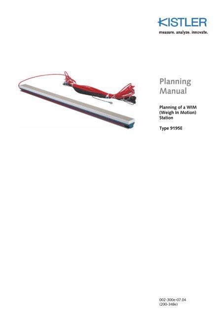
Planning<br />
<strong>Manual</strong><br />
Planning of a <strong>WIM</strong><br />
(Weigh In Motion)<br />
Station<br />
<strong>Type</strong> <strong>9195E</strong><br />
002-300e-07.04<br />
(200-348e)
Foreword<br />
Foreword<br />
Information in this document is subject to change without<br />
notice. Kistler reserves the right to change or improve its<br />
products and make changes in the content without<br />
obligation to notify any person or organization of such<br />
changes or improvements.<br />
© 2004, Kistler Instrumente AG. All rights reserved. Except<br />
as expressly provided herein, no part of this manual may<br />
be reproduced for any purpose without the express prior<br />
written consent of Kistler Instrumente AG.<br />
Kistler Instrumente AG<br />
Eulachstrasse 22<br />
CH-8408 Winterthur<br />
Switzerland<br />
Tel. +41 52 224 11 11<br />
Fax +41 52 224 14 14<br />
info@kistler.com<br />
www.kistler.com<br />
Your competent distributor:<br />
002-300e-07.04 (200-348e) Page 1
Content<br />
Planning of a <strong>WIM</strong> Station <strong>Type</strong> <strong>9195E</strong><br />
1. Introduction ................................................................................................................................... 3<br />
2. Precautions .................................................................................................................................... 4<br />
3. Why <strong>WIM</strong> Measurements? ............................................................................................................ 5<br />
4. How does the Lineas ®<br />
Sensor Measure? ........................................................................................ 6<br />
4.1 Tire – Lineas ®<br />
Interaction ................................................................................................... 6<br />
5. Signal Processing ........................................................................................................................... 8<br />
5.1 Charge Amplifier ............................................................................................................... 8<br />
5.2 Digitizing the analog signal................................................................................................ 9<br />
5.3 Processor algorithm requirements for optimum weight estimation................................... 10<br />
5.4 Influence of Velocity........................................................................................................ 11<br />
5.5 Electrical Connection ....................................................................................................... 11<br />
6. Requirements to the Road............................................................................................................ 13<br />
6.1 Summary .........................................................................................................................13<br />
6.2 Pavement Characteristics ................................................................................................. 13<br />
6.3 European Specification (COST 323)................................................................................. 14<br />
6.4 US Specification (ASTM Standard E1318) ........................................................................ 14<br />
7. Requirements to Hard- & Software .............................................................................................. 15<br />
7.1 Electronics........................................................................................................................ 15<br />
7.2 Software.......................................................................................................................... 15<br />
7.3 Facilities ........................................................................................................................... 16<br />
8. Typical Configuration of a <strong>WIM</strong> Station ...................................................................................... 17<br />
8.1 Recommendation ............................................................................................................ 17<br />
8.2 Layout of a <strong>WIM</strong> Station ................................................................................................. 18<br />
8.3 Spacing between Two Lineas ® <strong>WIM</strong> Sensor Rows............................................................ 23<br />
9. Installation of Lineas ®<br />
Sensors ..................................................................................................... 24<br />
10. Commissioning of a <strong>WIM</strong> Station................................................................................................ 25<br />
10.1 Mechanical and Electrical checking .................................................................................. 25<br />
10.2 Calibration....................................................................................................................... 25<br />
11. Inspection and Maintenance ........................................................................................................ 26<br />
12. Frequently Asked Questions (FAQ) ............................................................................................. 27<br />
13. Typical Installation Schedule........................................................................................................ 29<br />
14. Requirements for the Lineas ®<br />
Installation .................................................................................... 30<br />
15. Lineas ®<br />
Documentation................................................................................................................ 31<br />
Total pages: 31<br />
Page 2 002-300e-07.04 (200-348e)
Introduction<br />
1. Introduction<br />
We thank you for your interest in a Kistler quality product<br />
distinguished by technical innovation, precision and long<br />
life. Please take the time to thoroughly read this planning<br />
manual.<br />
Kistler offers a wide range of products for use in measuring<br />
technology:<br />
Quartz crystal sensors for force, torque, strain, pressure,<br />
acceleration, shock, vibration and acoustic-emission<br />
Piezo resistive pressure sensors and transmitters<br />
Signal conditioners, indicators and calibrators<br />
Electronic control and monitoring systems as well as<br />
application-specific software for measuring technology<br />
Kistler also develops and produces measuring solutions for<br />
the application fields engines, vehicles, manufacturing,<br />
plastics and biomechanics.<br />
Our product and application brochures will provide you<br />
with an overview of our product range. Detailed data<br />
sheets are available for almost all products.<br />
If you need additional help beyond what can be found<br />
either on-line or in this manual, please contact Kistler's<br />
extensive support organization.<br />
002-300e-07.04 (200-348e) Page 3
2. Precautions<br />
Planning of a <strong>WIM</strong> Station <strong>Type</strong> <strong>9195E</strong><br />
The installation of a <strong>WIM</strong> station is documented in<br />
the Kistler installation instructions doc. no. 002-301<br />
(EV06.<strong>9195E</strong>).<br />
For every <strong>WIM</strong> site a careful selection of the installation<br />
location is absolutely essential as the accuracy of the<br />
system strongly depends on the quality of the pavement<br />
and it’s locality. Therefore refer to the requirements of<br />
COST 323 standard specification draft (http://wim.zag.si)<br />
and ASTM 1318-02 standard (http://www.astm.org).<br />
Rutting, bumps and pavement cracks will impair the<br />
system performance. Straight highways with uniform<br />
vehicle speed and perfect flat pavements are best suited to<br />
achieve the best results.<br />
Therefore the planning and preparation of the installation<br />
shall be done as early as possible, also in view to minimize<br />
the distance between sensors and electronics (for cable<br />
lengths see doc. no. 000-488).<br />
Lineas <strong>WIM</strong> installations must be performed by staff<br />
who have attended training and who have been<br />
certified by Kistler for Lineas installations. Kistler<br />
declines any warranty responsibility if these instructions<br />
are not followed.<br />
For every Lineas installation a Warranty Protocol needs<br />
to be completed and signed by the certified engineer<br />
and sent to Kistler or your distributor within 2 weeks of<br />
the installation.<br />
Page 4 002-300e-07.04 (200-348e)
Why <strong>WIM</strong> Measurements?<br />
3. Why <strong>WIM</strong> Measurements?<br />
<strong>WIM</strong>, Weigh In Motion, or dynamic weight measurements,<br />
are used for a wide area of applications. Some of the most<br />
important are<br />
• Statistics<br />
How many vehicles per hour, types of vehicles, empty<br />
or fully loaded, number of axles, classification, speed<br />
and spacing between vehicles.<br />
• Overload Detection<br />
Pre Selection<br />
A <strong>WIM</strong> station a few kilometers upstream of the static<br />
scale monitors all vehicles. The overloaded trucks are<br />
then taken out of the traffic for inspection and static<br />
weighing.<br />
Weight Enforcement<br />
Law enforcement by means of high speed <strong>WIM</strong> which<br />
includes video/still cameras.<br />
Bridge & Construction Protection<br />
Preventing overweight vehicles from crossing a bridge<br />
of limited capacity. Can be combined with video/still<br />
cameras for law enforcement.<br />
• Toll Roads<br />
Measure vehicles for a weight-dependent toll. In future,<br />
the tolling will be based on the road user charge<br />
(weight-dependent) rather than by classification. A fully<br />
loaded truck therefore will be charged more than an<br />
empty truck, since a fully loaded truck uses the infrastructure<br />
to a much higher degree.<br />
• Road Research<br />
Research on the influence of traffic on pavements.<br />
• Pavement Management System<br />
Decision-making process designed to help authorities to<br />
prevent pavement problems through judicious maintenance,<br />
and to diagnose and repair damages in a<br />
timely, cost-effective manner.<br />
It consists of a comprehensive database and historical<br />
information on pavement condition, structure and traffic,<br />
and is a set of tools that allows determination of<br />
existing and future pavement conditions, predict financial<br />
needs, and identify and prioritize pavement preservation<br />
projects.<br />
002-300e-07.04 (200-348e) Page 5
4. How does the Lineas ®<br />
Sensor Measure?<br />
4.1 Tire – Lineas ® Interaction<br />
F y<br />
F z<br />
Planning of a <strong>WIM</strong> Station <strong>Type</strong> <strong>9195E</strong><br />
A wheel rolling over a Lineas applies vertical forces to the<br />
quartz crystals in the sensor, with virtually no deformation.<br />
The piezoelectric quartz disks yield an electrical charge<br />
proportional to the applied forces. The piezoelectric<br />
sensitivity is practically independent of temperature, time<br />
and speed. The electric charge signals are converted by a<br />
charge amplifier into exactly proportional voltages which<br />
can be further processed as required.<br />
The accuracy of the measured wheel load is not influenced<br />
by tire type, tire quantity or tire pressure. In case of dual<br />
tires, the Lineas measures one signal and expresses it as<br />
one wheel load, which is equal to the sum of both wheel<br />
loads.<br />
Truck or car tires with normal tread patterns won't affect<br />
the accuracy of the measurement.<br />
Lineas sensor installed:<br />
- red vertical force<br />
- yellow special elastic material<br />
- grey grouting compound<br />
- dark grey aluminum profile<br />
- blue quartz sensing elements<br />
- black asphalt or concrete<br />
As a tire passes over the Lineas sensor, it generates<br />
horizontal, vertical and lateral forces between tire and<br />
sensor. Due to the special sensor design, only vertical<br />
forces (F z ) are measured. Lateral and horizontal side forces<br />
(F x and F y ), between road and sensor, are decoupled by a<br />
special elastic material around the sensor. There are no<br />
errors caused by volume effects.<br />
A typical truck tire force signal, as sensed by the Lineas<br />
sensor, is shown below:<br />
F x<br />
Page 6 002-300e-07.04 (200-348e)<br />
F z<br />
Peak<br />
Wheel load 45 000 N<br />
Velocity 80 km/h<br />
Inflation pressure 8 bar<br />
20 ms<br />
t
How does the Lineas® Sensor Measure?<br />
The maximum of the force (= peak) doesn’t express the<br />
wheel load, because the Lineas-sensor is only partially<br />
covered by the tire!<br />
The typical force signals of a car tire with different inflation<br />
pressures is shown left. The footprint length is calculated<br />
by multiplying velocity by sensing time. The area under<br />
the curve is constant (and proportional to the wheel load),<br />
while peak and footprint length depend on the tire<br />
pressure.<br />
Wheel load 4 500 N<br />
Tire pressure from 0,7 bar (10 psi) to 2,5 bar (36 psi)<br />
Due to the use of piezoelectric quartz measuring elements,<br />
the output of the Lineas sensor is an electrical charge (Q),<br />
which is proportional to the applied vertical force F z and<br />
which is irrespective of the position of the wheel along the<br />
length of the sensor. The typical sensitivity of a Lineas<br />
sensor is 1,76 pC/N.<br />
Applied force onto sensor Charge output signal of Lineas<br />
F z<br />
vertical force Fz [N]<br />
1600<br />
1400<br />
1200<br />
1000<br />
800<br />
600<br />
400<br />
200<br />
0<br />
Q ~ F z<br />
0 5 10 15 20 25 30<br />
footprint length [cm]<br />
t t<br />
2.5 bar (36psi)<br />
2.0 bar (29psi)<br />
1.5 bar (22psi)<br />
1.0 bar (14psi)<br />
0.7 bar (10psi)<br />
002-300e-07.04 (200-348e) Page 7
5. Signal Processing<br />
5.1 Charge Amplifier<br />
Planning of a <strong>WIM</strong> Station <strong>Type</strong> <strong>9195E</strong><br />
The charge amplifier converts and amplifies the force<br />
dependent charge input into a force dependent voltage<br />
output. The range of the charge amplifier is typically<br />
60 000 pC/5 V.<br />
1,8 pC 5 V<br />
Sensitivity at the output of the charge amplifier = x = 0,15 mV/N<br />
N 60 000 pC<br />
Dimension example:<br />
Q ~ F z U ~ F z<br />
t t<br />
Charge output of Lineas Voltage output of charge amplifier<br />
Truck Tire: inflation pressure = 12 bar (174 psi)<br />
tire width = 0,35 m (13,8 in)<br />
analog voltage with ±5 V volt full-scale output limits<br />
nominal zero volt output @ zero load<br />
axle pass over the sensor produces a positive pulse<br />
Due to the fact that the sensor is partially covered by the tire, the peak may be approximated by the<br />
inflation pressure*:<br />
Force ≈ inflation pressure x tire width x sensor width<br />
Force ≈ 12 bar (174 psi) x 0,35 m (13,8 in) x 0,053 m (2,1 in) ≈ 2,3 kN<br />
Voltage ≈ force x sensitivity Lineas x range amplifier<br />
Voltage ≈ 22 300 N x 1,8 pC/N x 5 V / 60 000 pC ≈ 3,34 V<br />
* The real measured force (and voltage) is higher, due to additional tire dependent sidewall forces.<br />
Practically: A 9 t (20 000 lbs) axle produces a pulse peak of about 3,5 volts.<br />
Page 8 002-300e-07.04 (200-348e)
Signal Processing<br />
5.2 Digitizing the analog signal<br />
U ~ F z U ~ F z<br />
≥12-bit ADC resolution over ±5 V volt range<br />
Analog anti-aliasing filter (before the ADC) with ≈600 Hz<br />
low-pass cutoff<br />
t t<br />
The sampling rate can be approximated by the following<br />
formula:<br />
Sampling rate =<br />
velocity (m/s) x min. of measured points<br />
footprint length<br />
The minimum of measured points means the minimum<br />
quantity of sampling points per signal, to approximate the<br />
original force signal without loosing information, it should<br />
never fall below 10 to 20, even under best conditions.<br />
Examples:<br />
Truck Tire<br />
velocity 80 km/h =<br />
22,2 m/s (50 mph)<br />
number of measured points per curve 20<br />
footprint length 0,4 m<br />
22,2 m/s x 20<br />
Sampling rate = = 1 111 Hz<br />
0,4 m<br />
High inflated car tire<br />
velocity 150 km/h =<br />
41,6 m/s (93 mph)<br />
number of measured points per curve 10<br />
footprint length 0,15 m<br />
41,6 m/s x 10<br />
Sampling rate = = 2 778 Hz<br />
0,15 m<br />
Practically: 2 000 preferred<br />
002-300e-07.04 (200-348e) Page 9
Planning of a <strong>WIM</strong> Station <strong>Type</strong> <strong>9195E</strong><br />
5.3 Processor algorithm requirements for optimum weight estimation<br />
u(t)<br />
output voltage u(t)<br />
computed baseline b(t)<br />
t1-∆t t1 t2 t2+∆t<br />
(Start) (End)<br />
Threshold level<br />
define a threshold level so as to trigger at points t1 and t2<br />
define a ∆t such that t1-∆t = start point and t2+∆t =<br />
end point of signal processing<br />
compute area under sensor output curve between start<br />
point and end point<br />
Area is between output voltage u(t) and baseline b(t), where<br />
baseline is a straight line between start and end point:<br />
Area = ∫ [ u(t) - b(t) ] or, for the digitized signal:<br />
Area = ∑ [ u i - b i ] where the i's are sample numbers<br />
from start to end<br />
Wheel load (W) is the product of area (A), vehicle velocity<br />
(V), sensor width (L s ) and a calibration constant (C):<br />
Wheel load W = (V / L s ) x A x C<br />
Calibration constant C is determined by test with knownweight<br />
vehicle(s) and is held thereafter as a constant for<br />
use in weight estimation of any and all subsequent<br />
vehicles.<br />
No compensation algorithms are required for temperature<br />
effects, velocity effects or aging effects (because, for<br />
Lineas, there are none, except for the velocity multiplication<br />
step as shown above).<br />
Page 10 002-300e-07.04 (200-348e)<br />
t
Signal Processing<br />
5.4 Influence of Velocity<br />
Velocity can be determined from <strong>WIM</strong>-strip separation (a<br />
known distance) for each lane.<br />
For optimized vehicle classification, velocity should be<br />
measured by inductive loops to get the real vehicle lengths.<br />
Accurate velocity measurement is essential as it directly<br />
affects the accuracy of weight estimation!<br />
Area = A Area = A/2 Area = A/3<br />
5.5 Electrical Connection<br />
32 km/h 64 km/h 96 km/h<br />
(20 mph) (40 mph) (60 mph)<br />
The same wheel load of the same vehicle, when traversing<br />
a Lineas at 32 (20), 64 (40) and 96 km/h (60 mph), will<br />
produce pulses as shown above.<br />
The pulses will be identical in peak value, but will become<br />
"narrowed" in time as velocity increases.<br />
Multiplying the area of each case above by the associated<br />
velocity will produce a result that is identical for all three<br />
cases (or for any other velocity encountered).<br />
The resultant Velocity x Area is now proportional only to<br />
actual wheel load. The constant of the proportion is the<br />
calibration constant "C", which is determined by test with<br />
known-weight vehicles.<br />
The Lineas sensors are available in lengths of 0,75 m (29,5 in)<br />
and 1m (39,4 in). The sensors can be combined to cover<br />
the full width of a lane or of a road. Typically, 4 Lineas<br />
cover one lane. 2 Lineas sensors are typically connected in<br />
parallel as one channel prior to the charge amplifier. This<br />
kind of connection allows separate measurements of left<br />
and right wheel loads.<br />
In case of dual tires, the output signal of the connected<br />
Lineas sensors equals the sum of the dual tires loads.<br />
002-300e-07.04 (200-348e) Page 11
Planning of a <strong>WIM</strong> Station <strong>Type</strong> <strong>9195E</strong><br />
Lineas-row Charge amplifier Processing System<br />
F z Q ~ F z U ~ F z<br />
F z Q ~ F z U ~ F z<br />
Channel 1 (left)<br />
Channel 2 (right)<br />
rear wheels front wheels Channel 16<br />
Voltage signals at the output of the charge amplifier:<br />
Channel 1<br />
Channel 2<br />
U ~ F z left rear (dual) wheels left front wheel<br />
U ~ F z right rear (dual) wheels right front wheel<br />
In the special case that all 4 Lineas in one row have to be<br />
paralleled, the range of the charge amplifier should be<br />
increased to 100 000 pC/5 V.<br />
Page 12 002-300e-07.04 (200-348e)<br />
t<br />
t
Requirements to the Road<br />
6. Requirements to the Road<br />
6.1 Summary<br />
6.2 Pavement Characteristics<br />
Kistler requirements towards a Lineas installation: The pavement<br />
must not have rutting or deformations exceeding<br />
4 mm over the whole lane width. Each 40 cm before and<br />
after the sensors the unevenness of the pavement must not<br />
exceed 1 to 2 mm.<br />
In order to get high quality data, the following criteria must<br />
be met:<br />
Class 1 (excellent) according to COST 323 (ASTM 1318)<br />
Quasi static and dynamic deflection is minimal<br />
Minimum ruts<br />
Pavement is even (IRI Index)<br />
The main characteristics of a road, that are important, are<br />
the surface condition, road materials, road thickness,<br />
latitudinal and longitudinal slope, road curvature, rutting<br />
and cracking.<br />
Therefore not only the longitudinal evenness but also the<br />
deteriorations (such as rutting, deformation, cracking etc.)<br />
limit the accuracy of a measurement, and may reduce the<br />
<strong>WIM</strong> sensor durability or affect its response. The deflection<br />
and the transverse evenness may also affect the reliability<br />
and durability of the sensors.<br />
002-300e-07.04 (200-348e) Page 13
6.3 European Specification (COST 323)<br />
Planning of a <strong>WIM</strong> Station <strong>Type</strong> <strong>9195E</strong><br />
It is strongly recommended that the road section between<br />
50 m upstream and 25 m downstream of the system meets<br />
the following geometric characteristics:<br />
Longitudinal slope
Requirements to Hard- & Software<br />
7. Requirements to Hard- & Software<br />
7.1 Electronics<br />
7.2 Software<br />
Accuracy<br />
Each type of <strong>WIM</strong> electronics must be capable of<br />
performing the indicated functions within the accuracy<br />
class with respect to the application, shown in the ASTM<br />
(<strong>Type</strong> I – IV) and European standards (classes A5 – D25).<br />
Temperature range<br />
All electronic devices and components used must be able<br />
to operate in the temperature range –28 °C/+50 °C<br />
(ASTM) or –20 °C/+60 °C (EU). The stated accuracy<br />
should be maintained for ambient air temperatures at the<br />
<strong>WIM</strong> site!<br />
Humidity<br />
Relative humidity in the range of 0 to 90 % (not condensing)<br />
must be supported. Special conditions in<br />
tropical countries must be checked from site to site<br />
before planning.<br />
Lightning, electrical and magnetic field<br />
The electronics must be protected against lightning as<br />
well as against any external electrical or magnetic fields.<br />
High voltage, power line<br />
It is recommended that systems should not be installed<br />
under high voltage power lines, or close to radio transmitting<br />
and railway tracks.<br />
The <strong>WIM</strong> software should record at least the following<br />
information:<br />
Wheel load<br />
Axle load<br />
Axle group load<br />
Gross vehicle weight<br />
Speed<br />
Center-to-center spacing between axles<br />
Vehicle Class (via axle arrangement – distance)*<br />
Site identification code<br />
Lane and direction of travel<br />
Date and time of passage<br />
Sequential vehicle record number<br />
Wheelbase (front-most to rear-most axle)<br />
Vehicle length<br />
Violation code<br />
* Classification scheme – nearly every country, state or<br />
road administration has a preferred classification scheme<br />
for vehicles in its area of operation or responsibility.<br />
According to the product being used, one or many of these<br />
schemes will be provided in the <strong>WIM</strong> equipment.<br />
002-300e-07.04 (200-348e) Page 15
7.3 Facilities<br />
Planning of a <strong>WIM</strong> Station <strong>Type</strong> <strong>9195E</strong><br />
The availability of some additional facilities on the <strong>WIM</strong><br />
site is generally recommended.<br />
Electricity supply for <strong>WIM</strong> system operation<br />
Communication link (such as telephone line or other) to<br />
connect the <strong>WIM</strong> station if it is to be remotely monitored<br />
and for data collection<br />
Roadside cabinet to protect the <strong>WIM</strong> station against<br />
environment, vandalism etc.<br />
For calibration and testing purposes, it is recommended<br />
to have a static weighing area or a static scale close to<br />
the <strong>WIM</strong> site. A preferable site should allow for a<br />
reasonable run time for a calibration or test vehicle to<br />
perform a complete loop of the <strong>WIM</strong> site<br />
For maintenance works and checking of the <strong>WIM</strong> station it<br />
is recommended to have a parking lot close to the system<br />
It is important to avoid any overpass (aerodynamic<br />
effects) or bridge approach (poor evenness)<br />
It is not recommended to install road sensors on a bridge<br />
(without research reasons) or on any structure subject to<br />
dynamic effects.<br />
Page 16 002-300e-07.04 (200-348e)
Typical Configuration of a <strong>WIM</strong> Station<br />
8. Typical Configuration of a <strong>WIM</strong> Station<br />
8.1 Recommendation<br />
A complete installation consists of a total of 8 Lineas<br />
sensors, 2 rows of each four sensors, per traffic lane.<br />
Advantages:<br />
All information about the vehicle<br />
With two rows of 4 measuring channels (see Figures at<br />
page 18 to 22 for layouts of a <strong>WIM</strong> station), information<br />
about the speed can be acquired, also it is possible<br />
to evaluate the wheel loads separately. This also allows<br />
for evaluation and data processing of the precise gross<br />
vehicle weight, allowing for the differences between<br />
each wheel load (left and right). This will open up many<br />
evaluation possibilities, including:<br />
Different data processing for single axle load and group<br />
of axle loads – the cruise test between every axle in one<br />
group of axle<br />
Precise vehicle classification<br />
Asymmetric vehicle loading check (left to right)<br />
Individual calibration coefficient for every channel<br />
High accuracy of measured data<br />
Other possibilities dependent on software development<br />
and electronic equipment<br />
An automatic self calibration procedure can be developed<br />
002-300e-07.04 (200-348e) Page 17
Width of lane<br />
8.2 Layout of a <strong>WIM</strong> Station<br />
Channel 3<br />
Traffic direction<br />
Lane 1<br />
Channel 4<br />
Electronic cabinet<br />
Sensors & cables<br />
d<br />
Inductive loop & connection<br />
Planning of a <strong>WIM</strong> Station <strong>Type</strong> <strong>9195E</strong><br />
Channel 1<br />
Channel 2<br />
Page 18 002-300e-07.04 (200-348e)
Typical Configuration of a <strong>WIM</strong> Station<br />
(150, 175, 200)<br />
hard shoulder<br />
hard shoulder<br />
Dimensions in cm<br />
min.30<br />
min.30<br />
2<br />
Statistic <strong>WIM</strong><br />
2<br />
Lineas Sensor<br />
2<br />
'<br />
Electronic<br />
cabinet<br />
Electronic<br />
cabinet<br />
min.30<br />
Staggered <strong>WIM</strong><br />
2<br />
'<br />
Inductive loops<br />
min.30<br />
min.30<br />
driving direction<br />
002-300e-07.04 (200-348e) Page 19<br />
2<br />
(150, 175, 200)<br />
2<br />
'<br />
2 2' See cross cut<br />
section<br />
Sensor cable<br />
(150, 175, 200)<br />
driving direction
driving direction<br />
hard<br />
shoulder<br />
Standard <strong>WIM</strong> system of 1 lane<br />
min.30<br />
1<br />
min.30 min.30<br />
1<br />
'<br />
Electronic<br />
cabinet<br />
2 2'<br />
All dimensions in centimeter (cm)<br />
Planning of a <strong>WIM</strong> Station <strong>Type</strong> <strong>9195E</strong><br />
Page 20 002-300e-07.04 (200-348e)<br />
3<br />
3<br />
'<br />
Lineas sensor<br />
Inductive loops<br />
See cross cut section<br />
Sensor cable<br />
(300, 325, 350, 375, 400)
Typical Configuration of a <strong>WIM</strong> Station<br />
driving direction<br />
driving direction<br />
hard<br />
shoulder<br />
Road surface<br />
Foam strip<br />
Foam<br />
Standard <strong>WIM</strong> system of 2 lanes<br />
min.30<br />
min.30 min.30<br />
min. 30 min. 30<br />
min.30<br />
min.30 min.30<br />
1<br />
1<br />
'<br />
Electronic<br />
cabinet<br />
Screw<br />
Cross Cut 1-1<br />
002-300e-07.04 (200-348e) Page 21<br />
3<br />
min. 30<br />
8 mm<br />
Sand-epoxy<br />
Strassenbelag<br />
(Bitumen, Beton)<br />
grouting<br />
Flexible<br />
Vergussmasse<br />
72 mm ±3 mm<br />
Schutzschicht<br />
3<br />
'<br />
(300, 325, 350, 375, 400)<br />
(300, 325, 350, 375, 400)<br />
Level beam (for<br />
installation purpose)<br />
55 mm ± 3 mm<br />
Cable fixing clip<br />
Sensor cable in<br />
protection tube
Cross Cut 2-2 Cross-Cut 3-3<br />
min. 7mm<br />
Pavement<br />
(Bitumen, Concrete)<br />
min. 7 mm<br />
Min. 70 mm<br />
<strong>WIM</strong> sensors in concrete roads<br />
dilatation joint<br />
driving direction<br />
hard shoulder<br />
min. 30<br />
Flexible grouting<br />
or Bitumen<br />
Sand protection<br />
layer or foam<br />
tubing buffer<br />
Protected<br />
sensor cable<br />
Length of concrete slab<br />
Electronic<br />
cabinet<br />
Ground<br />
min. 30<br />
dilatation joint<br />
min. 30<br />
Planning of a <strong>WIM</strong> Station <strong>Type</strong> <strong>9195E</strong><br />
min. 50<br />
Page 22 002-300e-07.04 (200-348e)<br />
min. 80 mm<br />
min.10<br />
min.10<br />
Width of concrete slab<br />
Pavement<br />
(Bitumen, concrete)<br />
Flexible grouting<br />
or Bitumen<br />
Sand protection<br />
layer or foam<br />
tubing buffer<br />
Protected<br />
sensor cable<br />
Ground
Typical Configuration of a <strong>WIM</strong> Station<br />
8.3 Spacing between Two Lineas ® <strong>WIM</strong> Sensor Rows<br />
The spacing between two Lineas sensor rows depends<br />
mainly on the speed of the vehicles. The main body oscillation<br />
frequency is between 1,8 and 3,5 Hz, we recommend<br />
from experience that the spacing should be within 3 to<br />
5 m.<br />
In practice, there are good reasons to take into account,<br />
not only theoretical calculations, but also experience, for<br />
instance:<br />
The frequency spectrum strongly depends on the vehicle.<br />
Air suspension vehicles are nearer to 1 Hz than<br />
2,5 Hz for body oscillations and their damping characteristics<br />
are different from steel suspension types.<br />
Full or partial loading of vehicles severely affects the<br />
oscillation spectra, and there may be remarkable<br />
differences according to various vehicle populations per<br />
road and country.<br />
Further to body vibrations, the axle hop and tire natural<br />
frequencies are higher and important too.<br />
The overall accuracy is potentially influenced more by<br />
pavement unevenness than by a spacing of 5 m instead<br />
of 4 m. Even the slightest bumps many meters ahead of<br />
the sensors may give rise to oscillation, so the flatness<br />
between sensor and surrounding pavement is essential.<br />
An important practical aspect is that signal integration<br />
requires the individual velocities between the two<br />
sensor rows for each vehicle. Thus the longer the<br />
spacing, the higher the errors caused by acceleration or<br />
deceleration, namely at lower speeds.<br />
Therefore, in view of the many above influences and<br />
practical experience, we refrain from giving you deviation<br />
estimates for other spacing distances.<br />
Expected average velocity Recommended distance d<br />
45 - 75 km/h (30 to 45 mph) 3,5 m<br />
75 - 95 km/h (45 to 60 mph) 4,0 m<br />
>95 km/h (>60 mph) 4,5 m<br />
002-300e-07.04 (200-348e) Page 23
9. Installation of Lineas ®<br />
Sensors<br />
Planning of a <strong>WIM</strong> Station <strong>Type</strong> <strong>9195E</strong><br />
See Installation <strong>Instruction</strong>s 002-301 (EV06.<strong>9195E</strong>).<br />
As defined in the contract with different system integrators,<br />
the staff performing the installation of the sensors have to<br />
be trained by Kistler. These trained people will receive a<br />
certificate after theoretical training and after having performed<br />
successful installations under the supervision of a Kistler<br />
engineer. An employee certified by Kistler has to assist,<br />
supervise and sign a Lineas installation protocol which gives<br />
entitlement to an entire Kistler warranty.<br />
Page 24 002-300e-07.04 (200-348e)
Commissioning of a <strong>WIM</strong> Station<br />
10. Commissioning of a <strong>WIM</strong> Station<br />
10.1 Mechanical and Electrical checking<br />
10.2 Calibration<br />
Testing of sensors after installation:<br />
Mechanical checking<br />
Checking of the sensor state: no cracks, correct geometrical<br />
dimensions, etc.<br />
Proper setting of resin (no subsidence when vehicles pass)<br />
No deterioration around the sensors<br />
Connecting cables correctly protected by electrical<br />
sheaths, especially at corners<br />
Sufficient resistance against bending moment, according<br />
to the pavement deflection and the expected loads<br />
to be supported<br />
Electrical checking<br />
Insulation resistance<br />
Response per cable – this is read directly from an oscilloscope,<br />
under the effect of an impact delivered by the<br />
operator or the passage of a vehicle.<br />
Once the <strong>WIM</strong> sensors are installed and the grout has<br />
cured, retest the sensor (see installation instructions). In<br />
addition, it is recommended that an oscilloscope be connected<br />
to the sensors and typical wave form (signal form)<br />
be collected for a truck and a car. These signals should be<br />
printed out and saved for permanent record.<br />
The calibration should not be performed within 72 hours of<br />
the installation of the sensors. We suggest calibration<br />
of the site after 2 weeks of traffic having passed the<br />
<strong>WIM</strong> site.<br />
The calibration procedure is depending upon the end-users<br />
requirements. It should clearly state the type of vehicles,<br />
the number of runs, the loads, the equipment to be used<br />
and other relevant issues.<br />
002-300e-07.04 (200-348e) Page 25
11. Inspection and Maintenance<br />
Planning of a <strong>WIM</strong> Station <strong>Type</strong> <strong>9195E</strong><br />
Needless to say that a regular inspection and maintenance<br />
is required to keep the system in best possible condition<br />
and working order to generate quality data.<br />
Refer to the installation <strong>Instruction</strong>s 002-301 (EV06.<strong>9195E</strong>)<br />
and the Maintenance Protocol 900-556.<br />
Page 26 002-300e-07.04 (200-348e)
Frequently Asked Questions (FAQ)<br />
12. Frequently Asked Questions (FAQ)<br />
Available lengths of Lineas ® sensors<br />
The lengths of the Lineas sensors are 1,00 m and 0,75 m.<br />
For one row across a lane 4 sensors are usually required.<br />
The standard configuration is 2 sensor rows per lane.<br />
Please check carefully the actual lane width at the planned<br />
<strong>WIM</strong> sites and be aware that the regular cable length<br />
attached to the Lineas is 40 m and 100 m thus the electronic<br />
cabinet should not be too far away.<br />
Responsibility of an installation<br />
It is a requirement of Kistler that the installation is supervised<br />
by a Kistler engineer or Kistler certified engineer.<br />
This Kistler certified Engineer is responsible for the whole<br />
installation, the discontinuance in case the requirements<br />
are no longer met, as well as for the time of opening of the<br />
lane for traffic.<br />
Kistler is happy to assist and train the customer at cost price<br />
and will issue a certificate (for person not organization) if the<br />
installation and training were successful. The certificate is valid<br />
for a specified time.<br />
Companies who are interfacing the Lineas ®<br />
sensor<br />
There are several companies in Europe, North America, the<br />
Far East and Australia that have successfully adapted their<br />
electronics and software to integrate the Lineas sensor into<br />
their measuring chain.<br />
Regrinding of the Lineas ®<br />
sensor<br />
Lineas sensors have a topcoat with a thickness of 10 mm<br />
(the same material as the grouting material) designed for<br />
re-profiling by grinding less than 9 mm.<br />
If a pavement has a rut depth of e.g. 10 mm, the road<br />
cannot be regarded as a suitable <strong>WIM</strong> site, as vertical<br />
oscillations of the vehicles will induce dynamic weight<br />
deviations which exceed the requirements considerably.<br />
It is strongly recommended to have a pavement without<br />
rutting before installing the <strong>WIM</strong> site. If there is already a<br />
rutting of above 4mm, we suggest to repave the road. It is<br />
very important to have an even surface in order to achieve<br />
excellent results.<br />
Traveling over the Lineas ® sensor with a flat tire<br />
The load bearing capacity of the Lineas surface is over<br />
200 kN per twin wheel and local load concentrations up to<br />
the Mega Pascal range had been tested successfully. From<br />
all the sensors operating in many countries, we have no<br />
indication that flat runners have ever caused a failure.<br />
Performance over the total sensor length at delivery<br />
Kistler guarantees that all delivered Lineas sensors have a<br />
uniform sensitivity within +/-3 % over the length of the<br />
sensor. One channel usually consists of 2 sensors which are<br />
paired according to their sensitivity and have an uniformity<br />
of approx. +/-3 % over the width of the whole measuring<br />
channel.<br />
002-300e-07.04 (200-348e) Page 27
Planning of a <strong>WIM</strong> Station <strong>Type</strong> <strong>9195E</strong><br />
Our factory test certification fulfills this requirement<br />
irrespective of loading lengths between 100 and 300 mm.<br />
Calibration by pre-weighed vehicles is the most common<br />
procedure.<br />
Regular check of Lineas ®<br />
sensors<br />
The Lineas sensors themselves require at least bi-annual<br />
checks. Regular checks are advised in view of the condition<br />
of the pavement, the sensors as well as electronics servicing<br />
(power supply, batteries, contacts, and so on).<br />
See the Installation <strong>Instruction</strong>s 002-301 (EV06.<strong>9195E</strong>) and<br />
use the maintenance protocol 900-556.<br />
Installation into a new pavement<br />
Do not install in a new pavement within 72 hours after<br />
surfacing. This is to make sure that the tensions within the<br />
pavement have settled.<br />
Re-use of sensors<br />
If Lineas sensor are taken out of the pavement, they must<br />
not be used anymore.<br />
Place a new pavement<br />
To replace a new pavement the sensors should be taken<br />
out beforehand, ref. the doc 002-302 (200-349) backtracing<br />
and repair of a <strong>WIM</strong> station with Lineas.<br />
Page 28 002-300e-07.04 (200-348e)
Typical Installation Schedule<br />
13. Typical Installation Schedule<br />
One Lane of 8 Sensors<br />
Ideal conditions with a pavement and air temperature<br />
above +20 °C, dry condition of weather and pavement.<br />
This is an example of an installation schedule. The time for<br />
the grout curing depends on ambient air- and pavement<br />
temperatures. The lane must not be opened before the<br />
grouting has completely cured, refer the Installation<br />
<strong>Instruction</strong>s 002-301 (EV06.<strong>9195E</strong>).<br />
Time Work Personnel required<br />
00:00 Lane closure Police or authorized company for<br />
lane closure<br />
00:15 Marking, cut and clean slots for<br />
the Lineas sensor and for the<br />
inductive loops<br />
02:00 Heat and dry slots, pull cables<br />
through tube, install sensors<br />
1 men cutting, 3 to 4 men for slot<br />
preparation, tube preparation for<br />
the cables (if applicable)<br />
3 to 4 men<br />
04:00 Cable terminations 3 to 4 men<br />
06:30 Grind surface off, clean up 2 men<br />
07:30 Sensor tests 2 men<br />
08:00 Lane opening Police or authorized company<br />
002-300e-07.04 (200-348e) Page 29
14. Requirements for the Lineas ® Installation<br />
Planning of a <strong>WIM</strong> Station <strong>Type</strong> <strong>9195E</strong><br />
The installation of Lineas <strong>WIM</strong> sensors is documented in<br />
the doc 002-301 (EV06.<strong>9195E</strong>) Installation <strong>Instruction</strong>s.<br />
The checklist 200-369 lists all required materials, equipment<br />
and machinery which are necessary for an installation.<br />
Page 30 002-300e-07.04 (200-348e)
Lineas® Documentation<br />
15. Lineas ® Documentation<br />
Data Sheets<br />
• Doc.-No. 000-488<br />
Lineas Quartz Sensor for <strong>WIM</strong><br />
(Available in English and German)<br />
• Doc.-No. 000-114<br />
Industrial Charge Amplifier <strong>Type</strong> 5038A2Y43 for <strong>WIM</strong><br />
Lineas (for 2 channels)<br />
(Available only in English)<br />
• Doc.-No. 000-310<br />
Charge Amplifier <strong>Type</strong> 5153A for <strong>WIM</strong> Lineas (for 9 or<br />
18 channels)<br />
(Available in English and German)<br />
<strong>Instruction</strong> <strong>Manual</strong>s<br />
Doc.-No.002-301<br />
Installation <strong>Instruction</strong>s for Lineas Weigh in Motion<br />
Sensor <strong>Type</strong>s <strong>9195E</strong> (Available in English and German)<br />
Doc.-No. 002-224<br />
Charge Amplifier <strong>Type</strong> 5153A<br />
(Available in English and German)<br />
Doc.-No. 002-283<br />
Connection Box <strong>Type</strong> Z18753<br />
(Available in English and German)<br />
Papers<br />
Doc.-No. 20.205<br />
Crystal Clear, Traffic Technology International, Aug/<br />
Sep 1999<br />
(Available in English only)<br />
Doc.-No. 20.216<br />
The Goods and the Bad, Traffic Annual Review 2000<br />
(Available in English only)<br />
Doc.-No. 20.219<br />
Weigh and Toll as you Roll<br />
(Available in English only)<br />
CD-ROM<br />
Doc.-No. 200-305<br />
Lineas for <strong>WIM</strong><br />
Several<br />
Doc.-No. 200-369<br />
Checklist for Lineas Installation<br />
(Available in English and German)<br />
002-300e-07.04 (200-348e) Page 31


