

PMC-CPU/405 - esd electronics, Inc.
PMC-CPU/405 - esd electronics, Inc.
PMC-CPU/405 - esd electronics, Inc.

You also want an ePaper? Increase the reach of your titles
YUMPU automatically turns print PDFs into web optimized ePapers that Google loves.
1. Overview<br />
1.1 Description of the <strong>PMC</strong>-<strong>CPU</strong>/<strong>405</strong> Board<br />
RJ45<br />
10/100BaseT<br />
Serial 0<br />
RS-232<br />
DSUB9<br />
EEPROM<br />
10/100BaseT<br />
Transceiver<br />
RS-232<br />
Interface<br />
IBM<br />
PPC<strong>405</strong><br />
IRQ<br />
<strong>PMC</strong> Connector<br />
PLD<br />
Control Logic<br />
Overview<br />
<strong>PMC</strong>-<strong>CPU</strong>/<strong>405</strong> Hardware Manual Rev. 1.3 3<br />
Flash<br />
EPROM<br />
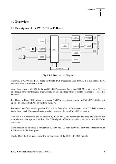
Fig. 1.1.1: Block circuit diagram<br />
(optional:<br />
NVRAM/RTC)<br />
RS-232<br />
Interface<br />
SDRAM<br />
CAN Controller<br />
SJA1000<br />
CAN Controller<br />
SJA1000<br />
The <strong>PMC</strong>-<strong>CPU</strong>/<strong>405</strong> is a <strong>PMC</strong>-board in ‘Single’ PCI Mezzanine Card format. It is available as <strong>PMC</strong><br />
monarch or as non-monarch board.<br />
Apart from a powerful <strong>CPU</strong> the PowerPC <strong>405</strong>GP processor has got an SDRAM controller, a PCI bus<br />
interface, a controller for serial interfaces and an MII-interface which is used to realize an ETHERNET<br />
interface.<br />
In addition to Flash EPROM and an optional NVRAM as system memory, the <strong>PMC</strong>-<strong>CPU</strong>/<strong>405</strong> has got<br />
up to 128 Mbytes SDRAM as working memory.<br />
Both serial interfaces are designed as RS-232 interfaces. One can be accessed via a DSUB9-connector<br />
in the front panel. The second serial interface is accessible via a <strong>PMC</strong>-I/O connector.<br />
The two CAN interfaces are controlled by SJA1000 CAN controllers and they are suitable for<br />
transmission rates up to 1 Mbit/s. The TTL-signals of both controllers are led to the <strong>PMC</strong>-I/O<br />
connector.<br />
The ETHERNET interface is suitable for 10 Mbit and 100 Mbit networks. They are connected via an<br />
RJ45-socket in the front panel.<br />
The LEDs in the front panel show the current status of the <strong>PMC</strong>-<strong>CPU</strong>/<strong>405</strong> module.<br />
CAN0-<br />
TTL<br />
CAN1-<br />
TTL<br />
Serial 1<br />
RS-232<br />
<strong>PMC</strong>-I/O Connector


