PMC-CPU/405 - esd electronics, Inc.
PMC-CPU/405 - esd electronics, Inc.
PMC-CPU/405 - esd electronics, Inc.
You also want an ePaper? Increase the reach of your titles
YUMPU automatically turns print PDFs into web optimized ePapers that Google loves.
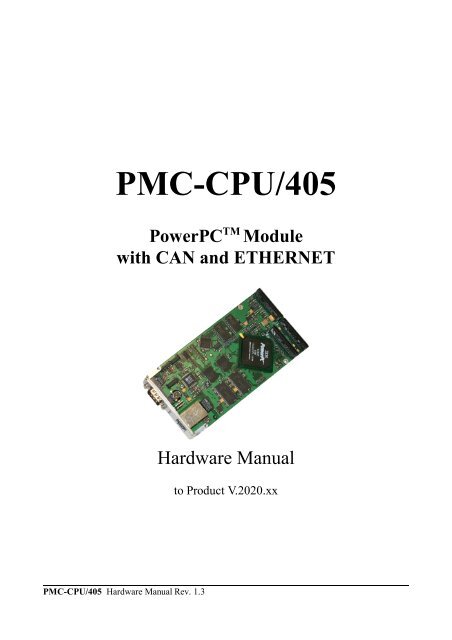
<strong>PMC</strong>-<strong>CPU</strong>/<strong>405</strong><br />
PowerPC TM Module<br />
with CAN and ETHERNET<br />
<strong>PMC</strong>-<strong>CPU</strong>/<strong>405</strong> Hardware Manual Rev. 1.3<br />
Hardware Manual<br />
to Product V.2020.xx
Document File: I:\texte\Doku\MANUALS\<strong>PMC</strong>\<strong>PMC</strong>-<strong>405</strong>\Englisch\<strong>PMC</strong>-<strong>405</strong>_13H.en9<br />
Date of print: 11.05.2005<br />
PCB:<br />
Changes in the chapters<br />
PPC-<strong>405</strong> from revision 1.1 with serial number from ABxxxx<br />
(PPC-<strong>405</strong> revision 1.0 up to serial number AAxxxx is described in hardware manual<br />
revision 1.1)<br />
The changes in the document listed below affect changes in the hardware as well as changes in the<br />
description of the facts, only.<br />
Chapter Changes as compared with previous version<br />
1.2.7 Software support updated.<br />
- -<br />
Technical details are subject to change without further notice.<br />
<strong>PMC</strong>-<strong>CPU</strong>/<strong>405</strong> Hardware Manual Rev. 1.3
<strong>PMC</strong>-<strong>CPU</strong>/<strong>405</strong> Hardware Manual Rev. 1.3<br />
N O T E<br />
The information in this document has been carefully checked and is believed to be entirely reliable. <strong>esd</strong><br />
makes no warranty of any kind with regard to the material in this document, and assumes no<br />
responsibility for any errors that may appear in this document. <strong>esd</strong> reserves the right to make changes<br />
without notice to this, or any of its products, to improve reliability, performance or design.<br />
<strong>esd</strong> assumes no responsibility for the use of any circuitry other than circuitry which is part of a product<br />
of <strong>esd</strong> gmbh.<br />
<strong>esd</strong> does not convey to the purchaser of the product described herein any license under the patent rights<br />
of <strong>esd</strong> gmbh nor the rights of others.<br />
<strong>esd</strong> electronic system design gmbh<br />
Vahrenwalder Str. 207<br />
30165 Hannover<br />
Germany<br />
Phone: +49-511-372 98-0<br />
Fax: +49-511-372 98-68<br />
E-mail: info@<strong>esd</strong>-<strong>electronics</strong>.com<br />
Internet: www.<strong>esd</strong>-<strong>electronics</strong>.com<br />
USA / Canada:<br />
<strong>esd</strong> <strong>electronics</strong> <strong>Inc</strong>.<br />
12 Elm Street<br />
Hatfield, MA 01038-0048<br />
USA<br />
Phone: +1-800-732-8006<br />
Fax: +1-800-732-8093<br />
E-mail: us-sales@<strong>esd</strong>-<strong>electronics</strong>.com<br />
Internet: www.<strong>esd</strong>-<strong>electronics</strong>.us
Contents<br />
1. Overview .................................................................3<br />
1.1 Description of the <strong>PMC</strong>-<strong>CPU</strong>/<strong>405</strong> Board .......................................3<br />
1.2 Summary of Technical Data .................................................4<br />
1.2.1 General Technical Data ..............................................4<br />
1.2.2 PCI Bus..........................................................4<br />
1.2.3 Microprocessor and Memory..........................................5<br />
1.2.4 Serial Interface ....................................................5<br />
1.2.5 CAN Interfaces ....................................................5<br />
1.2.6 ETHERNET-Interface...............................................6<br />
1.2.7 Software Support ..................................................6<br />
1.2.8 Order Information ..................................................7<br />
2. Front Panel View with LED-Display ...........................................8<br />
2.1 LEDs in the Front Panel ...................................................8<br />
3. Description of Units .........................................................9<br />
3.1 PowerPC <strong>405</strong>GP Microprocessor ............................................9<br />
3.1.1 General ..........................................................9<br />
3.1.2 Address Assignment ............................................... 10<br />
3.1.3 Interrupt Assignment ............................................... 11<br />
3.2 Serial Interface ......................................................... 12<br />
3.2.1 Default Setting ................................................... 12<br />
3.2.2 Configuration .................................................... 12<br />
4. Connector Assignment ..................................................... 13<br />
4.1 Assignment of the 64-pin <strong>PMC</strong> Connector P11 (Pn1/Jn1 32 Bit PCI)................. 13<br />
4.2 Assignment of the 64-pin <strong>PMC</strong> Connector P12 (PN2/Jn2 32 Bit PCI) ................ 14<br />
4.3 Assignment of the 64-pin <strong>PMC</strong>-I/O Connector P14 (CAN0, CAN1, Serial 1) .......... 15<br />
4.4 Serial Interface Serial0 at DSUB9 (X700) ..................................... 16<br />
4.5 ETHERNET 10/100BaseT Connection (X1100) ................................ 17<br />
<strong>PMC</strong>-<strong>CPU</strong>/<strong>405</strong> Hardware Manual Rev. 1.3 1
2<br />
This page is intentionally left blank.<br />
<strong>PMC</strong>-<strong>CPU</strong>/<strong>405</strong> Hardware Manual Rev. 1.3
1. Overview<br />
1.1 Description of the <strong>PMC</strong>-<strong>CPU</strong>/<strong>405</strong> Board<br />
RJ45<br />
10/100BaseT<br />
Serial 0<br />
RS-232<br />
DSUB9<br />
EEPROM<br />
10/100BaseT<br />
Transceiver<br />
RS-232<br />
Interface<br />
IBM<br />
PPC<strong>405</strong><br />
IRQ<br />
<strong>PMC</strong> Connector<br />
PLD<br />
Control Logic<br />
Overview<br />
<strong>PMC</strong>-<strong>CPU</strong>/<strong>405</strong> Hardware Manual Rev. 1.3 3<br />
Flash<br />
EPROM<br />
Fig. 1.1.1: Block circuit diagram<br />
(optional:<br />
NVRAM/RTC)<br />
RS-232<br />
Interface<br />
SDRAM<br />
CAN Controller<br />
SJA1000<br />
CAN Controller<br />
SJA1000<br />
The <strong>PMC</strong>-<strong>CPU</strong>/<strong>405</strong> is a <strong>PMC</strong>-board in ‘Single’ PCI Mezzanine Card format. It is available as <strong>PMC</strong><br />
monarch or as non-monarch board.<br />
Apart from a powerful <strong>CPU</strong> the PowerPC <strong>405</strong>GP processor has got an SDRAM controller, a PCI bus<br />
interface, a controller for serial interfaces and an MII-interface which is used to realize an ETHERNET<br />
interface.<br />
In addition to Flash EPROM and an optional NVRAM as system memory, the <strong>PMC</strong>-<strong>CPU</strong>/<strong>405</strong> has got<br />
up to 128 Mbytes SDRAM as working memory.<br />
Both serial interfaces are designed as RS-232 interfaces. One can be accessed via a DSUB9-connector<br />
in the front panel. The second serial interface is accessible via a <strong>PMC</strong>-I/O connector.<br />
The two CAN interfaces are controlled by SJA1000 CAN controllers and they are suitable for<br />
transmission rates up to 1 Mbit/s. The TTL-signals of both controllers are led to the <strong>PMC</strong>-I/O<br />
connector.<br />
The ETHERNET interface is suitable for 10 Mbit and 100 Mbit networks. They are connected via an<br />
RJ45-socket in the front panel.<br />
The LEDs in the front panel show the current status of the <strong>PMC</strong>-<strong>CPU</strong>/<strong>405</strong> module.<br />
CAN0-<br />
TTL<br />
CAN1-<br />
TTL<br />
Serial 1<br />
RS-232<br />
<strong>PMC</strong>-I/O Connector
Overview<br />
1.2 Summary of Technical Data<br />
1.2.1 General Technical Data<br />
4<br />
Ambient temperature 0...50 /C<br />
Humidity max. 90 %, non-condensing<br />
Power supply<br />
Connectors<br />
via <strong>PMC</strong> bus,<br />
5 V<br />
and<br />
3.3 V<br />
Dimensions 148.33 mm x 74.04 mm<br />
Weight 100 g<br />
1.2.2 PCI Bus<br />
P11 (64-pin <strong>PMC</strong> connector) - PCI signals<br />
P12 (64-pin <strong>PMC</strong> connector) - PCI signals<br />
P14 (64-pin <strong>PMC</strong> connector) - CAN-TTL interfaces CAN0 and<br />
CAN1, Serial 1 (RS-232 interface)<br />
X700 (9-pin DSUB, male) - Serial 0 (RS-232 interface)<br />
X720 (8-pin SMD socket) - Debug interface<br />
X1100 (8-pin RJ45 socket) - ETHERNET Twisted Pair (IEEE 802.3)<br />
Table 1.2.1: General technical data<br />
Host bus PCI bus in accordance with PCI Local Bus Specification 2.2<br />
PCI data 32 bits<br />
Processor PowerPC TM <strong>405</strong>GP<br />
Interrupt<br />
Non-monarch version: Interrupt signal A<br />
Monarch version: Interrupt signal A, B, C, D<br />
Table 1.2.2: PCI bus interface<br />
<strong>PMC</strong>-<strong>CPU</strong>/<strong>405</strong> Hardware Manual Rev. 1.3
1.2.3 Microprocessor and Memory<br />
Overview<br />
<strong>CPU</strong> PPC <strong>405</strong>GP / 200 MHz (max. 266 MHz) / 32 bit<br />
NVRAM optional, 32 K x 8 bits (optional: RTC instead of NVRAM)<br />
Flash-EPROM up to 4 M x 16 bit (8 Mbyte) Flash EPROM<br />
Serial EEPROM 1 Kbyte<br />
SDRAM<br />
1.2.4 Serial Interface<br />
Number 2<br />
Controlled PPC <strong>405</strong>GP<br />
8 M x 32 bit (32 Mbyte) (default)<br />
up to 32 M x 32 bit (128 Mbyte) (option)<br />
Table 1.2.3: Microprocessor and memory<br />
Bit rate<br />
Microcontroller:<br />
RS-232 transceiver:<br />
300 bit/s ... 115.200 bit/s<br />
max. 115.200 bit/s<br />
Physical interface Serial 0: RS-232C, Serial 1: RS-232C<br />
Connectors<br />
1.2.5 CAN Interfaces<br />
Serial 0: 9-pin DSUB-connector (male) in the front panel<br />
Serial 1: 64-pin <strong>PMC</strong>-connector on the board<br />
Table 1.2.4: Serial interface<br />
Number 2<br />
CAN controller SJA1000<br />
CAN protocol CAN 2.0A/2.0B<br />
Physical interface TTL-level<br />
Transmission rate 10 Kbit/s ... 1Mbit/s<br />
Bus termination has to be terminated externally<br />
Connectors 64-pin <strong>PMC</strong>-I/O connector (Pn4/Jn4 32 bit PCI)<br />
Table 1.2.5: CAN-interfaces<br />
<strong>PMC</strong>-<strong>CPU</strong>/<strong>405</strong> Hardware Manual Rev. 1.3 5
Overview<br />
1.2.6 ETHERNET-Interface<br />
6<br />
Number 1<br />
Bit rate 10 Mbit/s, 100 Mbit/s<br />
Processor PPC <strong>405</strong>GP<br />
Physical interface Twisted Pair (IEEE802.3) 10/100BaseT<br />
Electrical isolation via repeating coil<br />
Connector 8-pin RJ45-socket in front panel<br />
1.2.7 Software Support<br />
Table 1.2.6: ETHERNET-interface<br />
The boot monitor U-Boot *is stored in the Flash memory. This makes it possible for the <strong>PMC</strong>-<strong>CPU</strong>/<strong>405</strong><br />
to boot with various operating systems from the network or the local Flash memory.<br />
The operating systems Linux and VxWorks are available with corresponding drivers for the local<br />
interfaces. Further operating systems are available on request.<br />
Furthermore the CAN-transmission protocols CANopen and DeviceNet and a local WEB-server are<br />
available.<br />
* http://sourceforge.net/projects/u-boot/<br />
<strong>PMC</strong>-<strong>CPU</strong>/<strong>405</strong> Hardware Manual Rev. 1.3
1.2.8 Order Information<br />
Overview<br />
Type Properties Order No.<br />
<strong>PMC</strong>-<strong>CPU</strong>/<strong>405</strong> <strong>PMC</strong> Monarch<br />
IBM PPC <strong>405</strong>GP, 200 MHz, 32 MB SDRAM,<br />
4 MB Flash<br />
V.2020.02<br />
<strong>PMC</strong>-<strong>CPU</strong>/<strong>405</strong>-64 as V.2020.02 but 64 MB SDRAM V.2020.03<br />
<strong>PMC</strong>-<strong>CPU</strong>/<strong>405</strong>-A as V.2020.02 but <strong>PMC</strong> Non-monarch V.2020.12<br />
<strong>PMC</strong>-<strong>CPU</strong>/<strong>405</strong>-VxW VxWorksBSP V.2020.30<br />
<strong>PMC</strong>-<strong>CPU</strong>/<strong>405</strong>-Linux Linux BSP/adaption V.2020.32<br />
<strong>PMC</strong>-<strong>CPU</strong>/<strong>405</strong>-MD Manual in English 1*)<br />
(this manual)<br />
<strong>PMC</strong>-<strong>CPU</strong>/<strong>405</strong>-ENG Engineering manual in English 2*)<br />
Content: circuit diagrams, PCB top overlay<br />
drawing, data sheets of significant components<br />
1*) The manual is free, if it was ordered together with the product.<br />
2*) The manual is liable for costs, please contact our support<br />
Table 1.2.8: Order information<br />
V.2020.21<br />
V.2020.25<br />
<strong>PMC</strong>-<strong>CPU</strong>/<strong>405</strong> Hardware Manual Rev. 1.3 7
8<br />
Front Panel View with LED-Display<br />
2. Front Panel View with LED-Display<br />
The module has got three LEDs in the front panel.<br />
2.1 LEDs in the Front Panel<br />
Ethernet Interface<br />
X1100<br />
Serial Interface<br />
Serial 0<br />
X700<br />
5<br />
1<br />
8<br />
1<br />
9<br />
6<br />
Fig. 2.1.1: Position and colour of the LEDs<br />
LED Colour Name Display function (LED on)<br />
LED500A green <strong>CPU</strong>-ACT-LED<br />
LED500A (green): Board <strong>CPU</strong> RUN<br />
LED500B (green): CAN Active<br />
LED500C (green): Receive Status Ethernet<br />
local <strong>CPU</strong> is in RUN status (LED lights at every access to the<br />
SDRAM. The LED can be blinking or constantly on in normal<br />
operation)<br />
LED500B green CAN-IRQ-LED CAN-frames are being transmitted or received<br />
LED500C green RCV<br />
Receive-Status ETHERNET (reception of ETHERNETdata<br />
packages)<br />
Table 2.1.1: Display function of LEDs<br />
<strong>PMC</strong>-<strong>CPU</strong>/<strong>405</strong> Hardware Manual Rev. 1.3
3. Description of the Units<br />
3.1 PowerPC <strong>405</strong>GP Microprocessor<br />
3.1.1 General<br />
Description of the Units<br />
The general functions of the PowerPC <strong>405</strong>GP will not be explained in this manual. The manual of the<br />
processor can be downloaded from the homepage of the manufacturer IBM, at:<br />
http://www-3.ibm.com/chips/products/powerpc<br />
<strong>PMC</strong>-<strong>CPU</strong>/<strong>405</strong> Hardware Manual Rev. 1.3 9
Description of the Units<br />
3.1.2 Address-Assignment<br />
Start address<br />
[HEX]<br />
10<br />
End address<br />
[HEX]<br />
0x0000_0000 0x03FF_FFFF SDRAM (max. 64 Mbyte)<br />
0x8000_0000 0xEF5F_FFFF PCI core memory area<br />
Internal periphery:<br />
0xEF60_0300 0xEF60_0307 UART0-register (see PPC <strong>405</strong>GP manual table 3-6 , page 3-9) *<br />
0xEF60_0400 0xEF60_0407 UART1-register (see PPC <strong>405</strong>GP manual table 3-7 , page 3-10) *<br />
Unit<br />
0xEF60_0500 0xEF60_0510 IIC0-register (see PPC <strong>405</strong>GP-manual table 3-8 , page 3-11)<br />
0xEF60_0600 0xEF60_0601 OPB-arbiter register (see PPC <strong>405</strong>GP manual table 3-9 , page 3-12)<br />
0xEF60_0700 0xEF60_077F GPIO-controller register (see PPC <strong>405</strong>GP manual table 3-10 , page 3-13)<br />
0xEF60_0800 0xEF60_0867 Ethernet register (see PPC <strong>405</strong>GP manual table 3-11 , page 3-14)<br />
0xF000_0000 0xF000_001F CAN-controller CAN 0<br />
0xF000_0100 0xF000_011F CAN-controller CAN 1<br />
0xF020_0000 0xF020_7FFF optional NVRAM<br />
0xFFC0_0000 0xFFDF_FFFF Flash-EPROM bank 0<br />
0xFFE0_0000 0xFFFF_FFFF Flash-EPROM bank 1<br />
* The UARTs are 16550-compatible.<br />
Table 3.1.1: Addresses<br />
<strong>PMC</strong>-<strong>CPU</strong>/<strong>405</strong> Hardware Manual Rev. 1.3
3.1.3 Interrupt-Assignment<br />
Description of the Units<br />
Interrupt External IRQ Assignment Level Detection<br />
IRQ 25 EXT IRQ 0 CAN0 low active, level sensitive<br />
IRQ26 EXT IRQ 1 CAN1 low active, level sensitive<br />
IRQ 27 EXT IRQ 2 PCI-slot 0 low active, level sensitive<br />
IRQ 28 EXT IRQ 3 PCI-slot 1 low active, level sensitive<br />
IRQ 29 EXT IRQ 4 PCI-slot 2 low active, level sensitive<br />
IRQ 30 EXT IRQ 5 PCI-slot 3 low active, level sensitive<br />
Table 3.1.2: Assignment of the interrupts 25...30<br />
All other interrupt sources are PPC <strong>405</strong>GP -internal. They are described in the PowerPC <strong>405</strong>GP manual.<br />
<strong>PMC</strong>-<strong>CPU</strong>/<strong>405</strong> Hardware Manual Rev. 1.3 11
Description of the Units<br />
3.2 Serial Interface<br />
3.2.1 Default Setting<br />
The default setting of the serial interfaces is:<br />
Bit rate: 9600 Baud<br />
Data bits: 8<br />
Parity: no<br />
Stop bits: 1<br />
Handshake: XON/XOFF<br />
3.2.2 Configuration<br />
The serial interfaces are controlled by the PowerPC <strong>405</strong>GP processor. The bit rates of the interfaces can<br />
be configured by the software. The serial controller integrated in the PPC <strong>405</strong>GP and the RS-232-driver<br />
used for interface Serial 0 support bit rates of up to 115.2 kbit/s.<br />
The procedure to change the bit rate depends on the operating system. Please refer to the manual of the<br />
operating system.<br />
12<br />
<strong>PMC</strong>-<strong>CPU</strong>/<strong>405</strong> Hardware Manual Rev. 1.3
4. Connector Assignment<br />
Connector Assignment<br />
4.1 Assignment of the 64-pin <strong>PMC</strong> Connector P11 (Pn1/Jn1 32 Bit PCI)<br />
Signal Pin Pin Signal<br />
n.c. 1 2 -12V<br />
GND 3 4 INTA#<br />
INTB# 5 6 INTC#<br />
PRESENT# 7 8 VCC<br />
INTD# 9 10 n.c.<br />
GND 11 12 n.c.<br />
PCI-CLK 13 14 GND<br />
GND 15 16 GNT#<br />
REQ# 17 18 VCC<br />
V (I/O) 19 20 AD31<br />
AD28 21 22 AD27<br />
AD25 23 24 GND<br />
GND 25 26 C/BE3#<br />
AD22 27 28 AD21<br />
AD19 29 30 GND<br />
V (I/O) 31 32 AD17<br />
FRAME# 33 34 GND<br />
GND 35 36 IRDY#<br />
DEVSEL# 37 38 VCC<br />
GND 39 40 LOCK#<br />
n.c. 41 42 n.c.<br />
PAR 43 44 GND<br />
V (I/O) 45 46 AD15<br />
AD12 47 48 AD11<br />
AD09 49 50 VCC<br />
GND 51 52 C/BE0#<br />
AD06 53 54 AD05<br />
AD04 55 56 GND<br />
V (I/O) 57 58 AD03<br />
AD02 59 60 AD01<br />
AD00 61 62 VCC<br />
GND 63 64 n.c.<br />
<strong>PMC</strong>-<strong>CPU</strong>/<strong>405</strong> Hardware Manual Rev. 1.3 13
14<br />
Connector Assignment<br />
4.2 Assignment of the 64-pin <strong>PMC</strong> Connector P12 (PN2/Jn2 32 Bit PCI)<br />
Signal Pin Pin Signal<br />
+12 V 1 2 n.c.<br />
n.c. 3 4 TDO<br />
TDI 5 6 GND<br />
GND 7 8 n.c.<br />
n.c. 9 10 n.c.<br />
MODE2# 11 12 +3,3V<br />
RST# 13 14 MODE3#<br />
+3,3V 15 16 MODE4#<br />
n.c. 17 18 GND<br />
AD30 19 20 AD29<br />
GND 21 22 AD26<br />
AD24 23 24 +3,3V<br />
IDSEL 25 26 AD23<br />
+3,3V 27 28 AD20<br />
AD18 29 30 GND<br />
AD16 31 32 C/BE2#<br />
GND 33 34 IDSELB<br />
TRDY# 35 36 +3,3V<br />
GND 37 38 STOP#<br />
PERR# 39 40 GND<br />
+3,3V 41 42 SERR#<br />
C/BE1# 43 44 GND<br />
AD14 45 46 AD13<br />
GND 47 48 AD10<br />
AD08 49 50 +3,3V<br />
AD07 51 52 REQB#<br />
+3,3V 53 54 GNTB#<br />
n.c. 55 56 GND<br />
n.c. 57 58 EREADY<br />
GND 59 60 RESETOUT#<br />
n.c. 61 62 +3,3V<br />
GND 63 64 MONARCH#<br />
<strong>PMC</strong>-<strong>CPU</strong>/<strong>405</strong> Hardware Manual Rev. 1.3
Connector Assignment<br />
4.3 Assignment of the 64-pin <strong>PMC</strong>-I/O Connector P14 (CAN0, CAN1, Serial1)<br />
The connector P14 (PN4/Jn4 32 bit PCI) has been assigned with the Rx/Tx-Signals of both CAN<br />
controllers and with the serial interface Serial 1. The CAN-signals are TTL-level and they are not<br />
electrically isolated from the microcontroller units.<br />
Note: The pin assignment of connector P14 has changed from PCB reversion 1.0 to 1.1.<br />
The pin assignment of the connector shown in the table below is valid for boards from<br />
the serial number ABxxxx (delivery from October 2004).<br />
Signal Pin Pin Signal<br />
VCC 1 2 TX0-C0#<br />
TX1-C0# 3 4 RX0-C0#<br />
RX1-C0# 5 6 TX0-C1#<br />
TX1-C1# 7 8 RX0-C1#<br />
RX1-C1# 9 10 GND<br />
GND 11 12 n.c.<br />
n.c. 13 14 RXS1<br />
n.c. 15 16 TXS1<br />
CTSS1# 17 18 RTSS1#<br />
n.c. 19 20 GND<br />
n.c.<br />
21<br />
:<br />
63<br />
<strong>PMC</strong>-<strong>CPU</strong>/<strong>405</strong> Hardware Manual Rev. 1.3 15<br />
22<br />
:<br />
64<br />
n.c.
Connector Assignment<br />
4.4 Serial Interface Serial 0 at DSUB9 (X700)<br />
16<br />
Pin Position:<br />
Pin Assignment:<br />
Signal Pin Signal<br />
n.c. 6<br />
n.c. 7<br />
CTS 8<br />
n.c. 9<br />
9-pin DSUB connector<br />
1 n.c.<br />
2 RX<br />
3 TX<br />
4 RTS<br />
5 GND<br />
<strong>PMC</strong>-<strong>CPU</strong>/<strong>405</strong> Hardware Manual Rev. 1.3
4.5 ETHERNET 10/100BaseT Connector (X1100)<br />
Pin Position:<br />
1 2 3 4 5 6 7 8<br />
Cut-out for<br />
fastening lever<br />
Pin Assignment:<br />
Pin Signal<br />
1<br />
2<br />
3<br />
4<br />
5<br />
6<br />
7<br />
8<br />
8-pin RJ45-socket<br />
TP01 (TxD+)<br />
TP02 (TxD-)<br />
TP03 (RxD+)<br />
TP04<br />
TP05<br />
TP06 (RxD-)<br />
TP07<br />
TP08<br />
Connector Assignment<br />
<strong>PMC</strong>-<strong>CPU</strong>/<strong>405</strong> Hardware Manual Rev. 1.3 17


