

Download CAN-USB-Micro Hardware Manual - esd electronics, Inc.
Download CAN-USB-Micro Hardware Manual - esd electronics, Inc.
Download CAN-USB-Micro Hardware Manual - esd electronics, Inc.

Create successful ePaper yourself
Turn your PDF publications into a flip-book with our unique Google optimized e-Paper software.
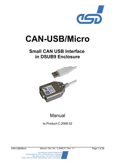
<strong>CAN</strong>-<strong>USB</strong>/<strong>Micro</strong><br />
Small <strong>CAN</strong> <strong>USB</strong> Interface<br />
in DSUB9 Enclosure<br />
<strong>Manual</strong><br />
to Product C.2068.02<br />
<strong>CAN</strong>-<strong>USB</strong>/<strong>Micro</strong> <strong>Manual</strong> • Doc. No.: C.2068.21 / Rev. 1.1 Page 1 of 36<br />
<strong>esd</strong> electronic system design gmbh<br />
Vahrenwalder Str. 207 • 30165 Hannover • Germany<br />
http://www.<strong>esd</strong>.eu • Fax: 0511/37 29 8-68<br />
Phone: 0511/37 29 80 • International: +49-5 11-37 29 80
N O T E<br />
The information in this document has been carefully checked and is believed to be entirely reliable.<br />
<strong>esd</strong> makes no warranty of any kind with regard to the material in this document, and assumes no<br />
responsibility for any errors that may appear in this document. <strong>esd</strong> reserves the right to make<br />
changes without notice to this, or any of its products, to improve reliability, performance or design.<br />
<strong>esd</strong> assumes no responsibility for the use of any circuitry other than circuitry which is part of a<br />
product of <strong>esd</strong> gmbh.<br />
<strong>esd</strong> does not convey to the purchaser of the product described herein any license under the patent<br />
rights of <strong>esd</strong> gmbh nor the rights of others.<br />
Trademark Notices<br />
<strong>esd</strong> electronic system design gmbh<br />
Vahrenwalder Str. 207<br />
30165 Hannover<br />
Germany<br />
Phone: +49-511-372 98-0<br />
Fax: +49-511-372 98-68<br />
E-Mail: info@<strong>esd</strong>.eu<br />
Internet: www.<strong>esd</strong>.eu<br />
USA / Canada:<br />
<strong>esd</strong> <strong>electronics</strong> <strong>Inc</strong>.<br />
525 Bernardston Road<br />
Suite 1<br />
Greenfield, MA 01301<br />
USA<br />
Phone: +1-800-732-8006<br />
Fax: +1-800-732-8093<br />
E-mail: us-sales@<strong>esd</strong>-<strong>electronics</strong>.com<br />
Internet: www.<strong>esd</strong>-<strong>electronics</strong>.us<br />
<strong>CAN</strong>open® and CiA® are registered community trademarks of <strong>CAN</strong> in Automation e.V.<br />
<strong>USB</strong> is a registered trademark of the Universal Serial Bus Implementers Forum, INC.<br />
Windows is a registered trademark of <strong>Micro</strong>soft Corporation in the United States and other countries.<br />
All other trademarks, product names, company names or company logos used in this manual are reserved by their<br />
respective owners.<br />
Page 2 of 36 <strong>Manual</strong> • Doc. No.: C.2068.21 / Rev. 1.1 <strong>CAN</strong>-<strong>USB</strong>/<strong>Micro</strong>
Document file:<br />
Date of print: 2011-06-06<br />
<strong>Hardware</strong> version: 1.1<br />
Firmware version: Since version 1.15<br />
Document History<br />
I:\Texte\Doku\MANUALS\<strong>CAN</strong>\<strong>CAN</strong>-<strong>USB</strong>-<strong>Micro</strong>\<strong>CAN</strong>-<strong>USB</strong>-<strong>Micro</strong>_<strong>Manual</strong>_en_11.odt<br />
The changes in the document listed below affect changes in the hardware as well as changes in<br />
the description of the facts, only.<br />
Revision Chapter Changes versus previous version Date<br />
1.0 - First version 2011-01-28<br />
1.1<br />
5.4, 12. Notes on software driver support inserted. 2011-06-01<br />
7.<br />
8.<br />
Documentation corrected: <strong>CAN</strong> interface is not<br />
electrically isolated. Editorial revision of the chapter.<br />
<strong>CAN</strong> transceiver test revised. Editorial revision of the<br />
chapter.<br />
2011-06-01<br />
2011-06-01<br />
12. Order information moved to chapter 12. 2011-06-01<br />
Technical details are subject to change without further notice.<br />
<strong>CAN</strong>-<strong>USB</strong>/<strong>Micro</strong> <strong>Manual</strong> • Doc. No.: C.2068.21 / Rev. 1.1 Page 3 of 36
Safety Instructions<br />
! When working with <strong>CAN</strong>-<strong>USB</strong>/<strong>Micro</strong> follow the instructions below and read the manual carefully to protect<br />
yourself and the <strong>CAN</strong>-<strong>USB</strong>/<strong>Micro</strong> from damage.<br />
The <strong>esd</strong> guarantee does not cover damages which result from improper use or disregard of safety<br />
instructions and warnings.<br />
! Protect the <strong>CAN</strong>-<strong>USB</strong>/<strong>Micro</strong> from dust, moisture and steam.<br />
! Protect the <strong>CAN</strong>-<strong>USB</strong>/<strong>Micro</strong> against shocks and vibrations.<br />
! The <strong>CAN</strong>-<strong>USB</strong>/<strong>Micro</strong> may become warm during normal use. Always allow adequate ventilation around<br />
the <strong>CAN</strong>-<strong>USB</strong>/<strong>Micro</strong> and use care when handling.<br />
! Do not operate the <strong>CAN</strong>-<strong>USB</strong>/<strong>Micro</strong> adjacent to heat sources and do not expose it to unnecessary<br />
thermal radiation. Ensure an ambient temperature as specified in the technical data.<br />
! Do not use damaged or defective cables to connect the <strong>CAN</strong>-<strong>USB</strong>/<strong>Micro</strong> and follow the <strong>CAN</strong> wiring hints<br />
in chapter: "Correctly Wiring of <strong>CAN</strong> Networks".<br />
Qualified Personal<br />
This documentation is directed exclusively towards qualified personal in control and automation engineering.<br />
The installation and commissioning of the product may only be carried out by qualified personal, which is<br />
authorized to put devices, systems and electric circuits into operation according to the applicable national<br />
standards of safety engineering.<br />
Conformity<br />
The <strong>CAN</strong>-<strong>USB</strong>/<strong>Micro</strong> meets the demands of the EU regulations and EMC standards printed in the conformity<br />
declaration at the end of this manual.<br />
Intended Use<br />
The intended use of the <strong>CAN</strong>-<strong>USB</strong>/<strong>Micro</strong> is the operation as a <strong>CAN</strong>-<strong>USB</strong> interface.<br />
The <strong>esd</strong> guarantee does not cover damages which result from improper use, usage not in accordance with<br />
regulations or disregard of safety instructions and warnings.<br />
! The operation of the <strong>CAN</strong>-<strong>USB</strong>/<strong>Micro</strong> in hazardous areas, or areas exposed to potentially explosive<br />
materials is not permitted.<br />
! The operation of the <strong>CAN</strong>-<strong>USB</strong>/<strong>Micro</strong> for medical purposes is prohibited.<br />
Service Note<br />
The <strong>CAN</strong>-<strong>USB</strong>/<strong>Micro</strong> does not contain any parts that require maintenance by the user. The <strong>CAN</strong>-<strong>USB</strong>/<strong>Micro</strong><br />
does not require any manual configuration of the hardware. Unauthorized intervention in the device voids<br />
warranty claims.<br />
Disposal<br />
Devices which have become defective in the long run have to be disposed in an appropriate way or have to<br />
be returned to the manufacturer for proper disposal. Please, make a contribution to environmental protection.<br />
Page 4 of 36 <strong>Manual</strong> • Doc. No.: C.2068.21 / Rev. 1.1 <strong>CAN</strong>-<strong>USB</strong>/<strong>Micro</strong>
Table of contents<br />
1. Overview......................................................................................................................................6<br />
1.1 Module Description................................................................................................................6<br />
2. View of the Connectors................................................................................................................7<br />
3. <strong>Hardware</strong> Installation....................................................................................................................8<br />
4. LED Description...........................................................................................................................9<br />
5. Summary of Technical Data.......................................................................................................10<br />
5.1 General Technical Data.......................................................................................................10<br />
5.2 <strong>USB</strong> Interface .....................................................................................................................10<br />
5.3 <strong>CAN</strong> Interface......................................................................................................................10<br />
5.4 Software Support.................................................................................................................11<br />
5.5 Firmware License.................................................................................................................11<br />
6. Connector Assignment...............................................................................................................12<br />
6.1 <strong>USB</strong>.....................................................................................................................................12<br />
6.2 <strong>CAN</strong> ....................................................................................................................................13<br />
7. Correctly Wiring of <strong>CAN</strong> Networks..............................................................................................14<br />
7.1 General Rules......................................................................................................................14<br />
7.2 Cabling................................................................................................................................15<br />
7.3 Termination..........................................................................................................................15<br />
7.4 Earthing...............................................................................................................................16<br />
7.5 Bus Length...........................................................................................................................16<br />
7.6 Examples for <strong>CAN</strong> Cables...................................................................................................17<br />
8. <strong>CAN</strong>-Bus Troubleshooting Guide...............................................................................................18<br />
8.1 Termination..........................................................................................................................18<br />
8.2 Ground.................................................................................................................................19<br />
8.3 Short Circuit in <strong>CAN</strong> Wiring..................................................................................................19<br />
8.4 <strong>CAN</strong>_H/<strong>CAN</strong>_L-Voltage ......................................................................................................19<br />
8.5 <strong>CAN</strong> Transceiver Resistance Test ......................................................................................20<br />
9. Software.....................................................................................................................................21<br />
9.1 Installation and Configuration under Windows XP...............................................................21<br />
10. Appendix..................................................................................................................................25<br />
11. Declaration of Conformity.........................................................................................................35<br />
12. Order Information.....................................................................................................................36<br />
<strong>CAN</strong>-<strong>USB</strong>/<strong>Micro</strong> <strong>Manual</strong> • Doc. No.: C.2068.21 / Rev. 1.1 Page 5 of 36
Overview<br />
1. Overview<br />
1.1 Module Description<br />
C<br />
A<br />
N<br />
B<br />
U<br />
S<br />
DSUB9 Enclosure<br />
DSUB9<br />
Male Contacts<br />
CiA ® Pin Assignment<br />
Physical<br />
<strong>CAN</strong> Layer<br />
ISO11898-2<br />
LED<br />
green<br />
LED<br />
red<br />
Power<br />
Supply<br />
3.3 V<br />
<strong>CAN</strong> <strong>Micro</strong>controller<br />
<strong>USB</strong> PWR<br />
<strong>USB</strong> Data<br />
1.0 m <strong>USB</strong> Cable<br />
Figure 1: Block-circuit diagram of the <strong>CAN</strong>-<strong>USB</strong>/<strong>Micro</strong><br />
The <strong>CAN</strong>-<strong>USB</strong>/<strong>Micro</strong> is a very small, low cost <strong>CAN</strong>-<strong>USB</strong> interface for PCs, that fits into a DSUB9<br />
enclosure. The ARM Cortex-M3 micro controller controls the <strong>CAN</strong> data. The non isolated <strong>CAN</strong><br />
interface is powered by <strong>USB</strong>.<br />
The <strong>CAN</strong>-<strong>USB</strong>/<strong>Micro</strong> supports the <strong>USB</strong> 2.0 full-speed interface with data rates up to 12 MBit/s.<br />
<strong>USB</strong> Type A<br />
Connector<br />
Serial line <strong>CAN</strong> interface (SL<strong>CAN</strong>) is used as the firmware interface.<br />
A Windows driver (NT<strong>CAN</strong>-API), with the usage limited to one application at a time, is available for<br />
Windows XP/ Vista / 7 (32/64 Bit).<br />
A Windows driver with full featured NT<strong>CAN</strong>-API support is available as an option.<br />
For Linux operating systems the <strong>CAN</strong>-<strong>USB</strong>/<strong>Micro</strong> is fully supported by the Socket<strong>CAN</strong> project and<br />
the SL<strong>CAN</strong> device driver, that is part of recent Linux kernels.<br />
Page 6 of 36 <strong>Manual</strong> • Doc. No.: C.2068.21 / Rev. 1.1 <strong>CAN</strong>-<strong>USB</strong>/<strong>Micro</strong>
2. View of the Connectors<br />
Figure 2: Connectors of <strong>CAN</strong>-<strong>USB</strong>/<strong>Micro</strong><br />
View of the Connectors<br />
<strong>CAN</strong>-<strong>USB</strong>/<strong>Micro</strong> <strong>Manual</strong> • Doc. No.: C.2068.21 / Rev. 1.1 Page 7 of 36
<strong>Hardware</strong> Installation<br />
3. <strong>Hardware</strong> Installation<br />
<br />
Procedure:<br />
Read the safety instructions at the beginning of this document carefully,<br />
before you start with the hardware installation!<br />
1. Connect the <strong>USB</strong> connector of the <strong>CAN</strong>-<strong>USB</strong>/<strong>Micro</strong> to the <strong>USB</strong> bus of the PC.<br />
2. Connect the 9-pin male DSUB connector to the <strong>CAN</strong> bus.<br />
Please remember that the <strong>CAN</strong> bus has to be terminated at both ends. <strong>esd</strong> offers<br />
T-connectors and terminators. Additionally, the <strong>CAN</strong>-GND-signal has to be grounded at<br />
exactly one point in the <strong>CAN</strong> network. Therefore the <strong>CAN</strong> termination connectors have got a<br />
grounding contact. A <strong>CAN</strong> device whose <strong>CAN</strong> interface is not electrically isolated (like the<br />
<strong>CAN</strong>-<strong>USB</strong>/<strong>Micro</strong>) corresponds to the grounding of the <strong>CAN</strong>-GND.<br />
3. End of hardware installation.<br />
4. The software installation is described exemplary in the chapter 'Installation and Configuration<br />
under Windows XP' on page 21.<br />
Page 8 of 36 <strong>Manual</strong> • Doc. No.: C.2068.21 / Rev. 1.1 <strong>CAN</strong>-<strong>USB</strong>/<strong>Micro</strong>
4. LED Description<br />
Figure 3: LEDs <strong>CAN</strong>-<strong>USB</strong>/<strong>Micro</strong><br />
Name Colour Description<br />
Activity green<br />
<strong>CAN</strong>-Error red<br />
on<br />
<strong>USB</strong> module is enumerated (a node address is<br />
assigned to the <strong>USB</strong> module)<br />
flash off receives <strong>CAN</strong> telegrams or <strong>USB</strong> commands<br />
off not working<br />
on<br />
<strong>CAN</strong>-Bus-off,<br />
<strong>CAN</strong>-Error-passive or<br />
<strong>CAN</strong>-Controller-Warn<br />
off <strong>CAN</strong> bus OK, (<strong>CAN</strong>-Error-active)<br />
LED Description<br />
LED-<br />
Description in<br />
Schematics<br />
Diagram<br />
LED102<br />
LED103<br />
<strong>CAN</strong>-<strong>USB</strong>/<strong>Micro</strong> <strong>Manual</strong> • Doc. No.: C.2068.21 / Rev. 1.1 Page 9 of 36
Summary of Technical Data<br />
5. Summary of Technical Data<br />
5.1 General Technical Data<br />
Temperature range 0...50°C ambient temperature<br />
Humidity 90% non-condensing<br />
Power supply via <strong>USB</strong>:<br />
nominal voltage:<br />
current consumption<br />
(without <strong>CAN</strong> traffic):<br />
5 V +5 % /-12%<br />
typical at 5 V : 50 mA<br />
Connectors <strong>USB</strong> - <strong>USB</strong> 2.0 interface (<strong>USB</strong> type A plug, X100)<br />
<strong>CAN</strong> - <strong>CAN</strong> interface (9-pin DSUB, male connector, X200)<br />
Dimensions cable length 1 m including connectors,<br />
DSUB9: 35 mm x 15 mm x 45 mm<br />
IP rating IP20<br />
Weight approx. 100 g<br />
5.2 <strong>USB</strong> Interface<br />
Number 1x <strong>USB</strong><br />
Controller integrated in ARM-Cortex-M3 STM32F105, 32-bit, 72 MHz<br />
<strong>USB</strong> interface <strong>USB</strong> 2.0, Full-Speed, 12 Mbit/s<br />
Connector <strong>USB</strong> type A plug<br />
5.3 <strong>CAN</strong> Interface<br />
Number of <strong>CAN</strong><br />
interfaces<br />
1x integrated in DSUB9-enclosure<br />
<strong>CAN</strong> controller integrated in ARM-Cortex-M3 STM32F105, 32 bit, 72 MHz<br />
<strong>CAN</strong> protocol ISO 11898-1<br />
Physical Layer<br />
Electrical isolation none<br />
<strong>CAN</strong> High speed interface according to ISO 11898-2,<br />
bit rate up to 1 Mbit/s<br />
Bus termination has to be set externally<br />
Connector DSUB9, according to DS-303-1<br />
Page 10 of 36 <strong>Manual</strong> • Doc. No.: C.2068.21 / Rev. 1.1 <strong>CAN</strong>-<strong>USB</strong>/<strong>Micro</strong>
5.4 Software Support<br />
Summary of Technical Data<br />
The <strong>CAN</strong>-<strong>USB</strong>/<strong>Micro</strong> runs with the standard <strong>USB</strong>-serial system drivers of common operating<br />
systems.<br />
A Windows driver (NT<strong>CAN</strong>-API), with the usage limited to one application at a time for Windows<br />
XP / Vista / 7 (32/64 Bit) and <strong>esd</strong>'s <strong>CAN</strong> Tools are in the scope of delivery.<br />
5.5 Firmware License<br />
As firmware the <strong>CAN</strong>-<strong>USB</strong>/<strong>Micro</strong> uses the open-source operating system FreeRTOS<br />
(www.freertos.org).<br />
The source code of the operating system is published in terms of the GNU Public License (GPL).<br />
The full text of the license is printed in the document '3rd party licensor notice.pdf' as part of the<br />
product's documentation. You can contact <strong>esd</strong> for the complete FreeRTOS source code for the<br />
<strong>CAN</strong>-<strong>USB</strong>/<strong>Micro</strong>.<br />
<strong>CAN</strong>-<strong>USB</strong>/<strong>Micro</strong> <strong>Manual</strong> • Doc. No.: C.2068.21 / Rev. 1.1 Page 11 of 36
Connector Assignment<br />
6. Connector Assignment<br />
6.1 <strong>USB</strong><br />
Device connector: <strong>USB</strong> connector type A<br />
Signal Description:<br />
VBUS... +5 V power supply voltage<br />
D+, D-... <strong>USB</strong> signal lines Data+, Data-<br />
GND... Reference potential<br />
Pin Position:<br />
Pin Assignment:<br />
Pin Signal<br />
1<br />
1 2 3 4<br />
V BUS<br />
2 D-<br />
3 D+<br />
4 GND<br />
Page 12 of 36 <strong>Manual</strong> • Doc. No.: C.2068.21 / Rev. 1.1 <strong>CAN</strong>-<strong>USB</strong>/<strong>Micro</strong>
6.2 <strong>CAN</strong><br />
Device connector: 9-pin DSUB connector, male<br />
Signal Description:<br />
Pin Position:<br />
Pin Assignment:<br />
Signal Pin Signal<br />
reserved 1<br />
<strong>CAN</strong>_L 2<br />
<strong>CAN</strong>_GND 3<br />
reserved 4<br />
<strong>CAN</strong>_GND<br />
(<strong>CAN</strong>_Shield)<br />
<strong>CAN</strong>_L, <strong>CAN</strong>_H <strong>CAN</strong> signal lines<br />
1 2 3 4 5<br />
6 7 8 9<br />
5<br />
6 reserved<br />
7 <strong>CAN</strong>_H<br />
8 reserved<br />
9 reserved<br />
<strong>CAN</strong>_GND reference potential of local <strong>CAN</strong> physical layer<br />
reserved reserved for future applications, do not connect!<br />
Connector Assignment<br />
<strong>CAN</strong>-<strong>USB</strong>/<strong>Micro</strong> <strong>Manual</strong> • Doc. No.: C.2068.21 / Rev. 1.1 Page 13 of 36
Correctly Wiring of <strong>CAN</strong> Networks<br />
7. Correctly Wiring of <strong>CAN</strong> Networks<br />
For the <strong>CAN</strong> wiring all applicable rules and regulations (EC, DIN), e.g. regarding electromagnetic<br />
compatibility, security distances, cable cross-section or material, have to be met.<br />
7.1 General Rules<br />
The following general rules for the <strong>CAN</strong> wiring must be followed:<br />
1 A cable type with a wave impedance of about 120 Ω ±10% with an adequate wire cross-section (0.22<br />
mm²) has to be used. The voltage drop over the wire has to be considered!<br />
2 Connect<br />
•<br />
•<br />
the two twisted wires to the data signals (<strong>CAN</strong>_H, <strong>CAN</strong>_L) and<br />
the cable shield to the reference potential (<strong>CAN</strong>_GND)!<br />
3 The reference potential <strong>CAN</strong>_GND has to be connected to the functional earth (FE) at exactly one<br />
point.<br />
The <strong>CAN</strong>-<strong>USB</strong>/<strong>Micro</strong> connects <strong>CAN</strong>_GND and FE, so no further connection should be made!<br />
4 A <strong>CAN</strong> net must not branch (exception: short cable stubs) and has to be terminated with the<br />
characteristic impedance of the line (generally 120 Ω ±10%) at both ends (between the signals<br />
<strong>CAN</strong>_L and <strong>CAN</strong>_H and not at GND)!<br />
5 Keep cable stubs as short as possible (l < 0.3 m)!<br />
6 Select a working combination of bit rate and cable length.<br />
7 Keep away cables from disturbing sources. If this cannot be avoided, double shielded wires are<br />
recommended.<br />
<strong>CAN</strong>_H<br />
<strong>CAN</strong>_L<br />
Wire Layout<br />
<strong>CAN</strong>_GND<br />
Single shielded<br />
twisted pair cable<br />
(two-wire cable,<br />
1x 2x 0.22mm²)<br />
120 Ohm<br />
Signal assignment of single shielded twisted pair cable<br />
with earth and termination<br />
<strong>CAN</strong> wire with connectors<br />
DSUB9 connector<br />
DSUB9 connector<br />
(female or male)<br />
(female or male)<br />
pin designation<br />
<strong>CAN</strong>_GND (at wire shield)<br />
pin designation<br />
1<br />
2<br />
n.c.<br />
<strong>CAN</strong>_L<br />
n.c. 1<br />
2<br />
3<br />
3<br />
4 n.c.<br />
n.c. 4<br />
5 n.c.<br />
n.c. 5<br />
6<br />
7<br />
n.c.<br />
<strong>CAN</strong>_H<br />
n.c. 6<br />
7<br />
8 n.c.<br />
n.c. 8<br />
9 n.c.<br />
n.c. 9<br />
connector case n.c.<br />
n.c. = not connected<br />
n.c. connector case<br />
Figure. 4: <strong>CAN</strong> wiring with single shielded twisted pair cables<br />
<strong>CAN</strong>_GND<br />
Page 14 of 36 <strong>Manual</strong> • Doc. No.: C.2068.21 / Rev. 1.1 <strong>CAN</strong>-<strong>USB</strong>/<strong>Micro</strong><br />
120 Ohm<br />
earth (FE)
7.2 Cabling<br />
Correctly Wiring of <strong>CAN</strong> Networks<br />
● For devices which have only one <strong>CAN</strong> connector per net use T-connector and stub (shorter<br />
than 0.3 m) (available as accessory).<br />
Figure. 5: Example for proper wiring with single shielded single twisted pair wires<br />
7.3 Termination<br />
● Use external termination plugs, because they can be rediscovered more easily than internal<br />
terminations within the <strong>CAN</strong> devices!<br />
● 9-pin DSUB-termination connectors with male and female contacts and earth terminal are<br />
available as accessories.<br />
<strong>CAN</strong>-<strong>USB</strong>/<strong>Micro</strong> <strong>Manual</strong> • Doc. No.: C.2068.21 / Rev. 1.1 Page 15 of 36
Correctly Wiring of <strong>CAN</strong> Networks<br />
7.4 Earthing<br />
● <strong>CAN</strong>_GND has to be connected to the functional earth potential (FE) at exactly one point<br />
of the network!<br />
● Each <strong>CAN</strong> interface without electrically isolated interface like the <strong>CAN</strong>-<strong>USB</strong>/<strong>Micro</strong> acts as<br />
an earthing point. For this reason do not connect more than one <strong>CAN</strong> device without<br />
electrically isolated <strong>CAN</strong> interface!<br />
● Earthing can e.g. be made at a connector.<br />
7.5 Bus Length<br />
● <strong>esd</strong> modules typically reach a wire length of 37 m at 1 Mbit/s within a closed net without<br />
impedance disturbances like e.g. cable stubs >> 0.3 m.<br />
Bit rate<br />
[Kbits/s]<br />
1000<br />
800<br />
666.6<br />
500<br />
333.3<br />
250<br />
166<br />
125<br />
100<br />
66.6<br />
50<br />
33.3<br />
20<br />
12.5<br />
10<br />
Typical values of reachable<br />
wire length with <strong>esd</strong><br />
interface l max [m]<br />
37<br />
59<br />
80<br />
130<br />
180<br />
270<br />
420<br />
570<br />
710<br />
1000<br />
1400<br />
2000<br />
3600<br />
5400<br />
7300<br />
CiA recommendations<br />
(07/95) for reachable wire<br />
lengths l min [m]<br />
25<br />
50<br />
-<br />
100<br />
-<br />
250<br />
-<br />
500<br />
650<br />
-<br />
1000<br />
-<br />
2500<br />
-<br />
5000<br />
Table 1: Recommended cable lengths at typical bit rates (with <strong>esd</strong>-<strong>CAN</strong> interfaces)<br />
Note:<br />
Please note the recommendations according to ISO 11898 for the selection of the cross<br />
section of the wire depending of the wire length.<br />
Page 16 of 36 <strong>Manual</strong> • Doc. No.: C.2068.21 / Rev. 1.1 <strong>CAN</strong>-<strong>USB</strong>/<strong>Micro</strong>
7.6 Examples for <strong>CAN</strong> Cables<br />
Manufacturer Type of wire<br />
U.I. LAPP GmbH<br />
Schulze-Delitzsch-Straße 25<br />
70565 Stuttgart<br />
Germany<br />
www.lappkabel.de<br />
ConCab GmbH<br />
Äußerer Eichwald<br />
74535 Mainhardt<br />
Germany<br />
www.concab.de<br />
Correctly Wiring of <strong>CAN</strong> Networks<br />
e.g.<br />
UNITRONIC ®-BUS <strong>CAN</strong> UL/CSA (1x 2x 0.22)<br />
(UL/CSA approved) Part No.: 2170260<br />
UNITRONIC ®-BUS-FD P <strong>CAN</strong> UL/CSA (1x 2x 0.25)<br />
(UL/CSA approved) Part No.: 2170272<br />
e. g.<br />
BUS-PVC-C (1x 2x 0,22 mm²) Order No.: 93 022 016 (UL appr.)<br />
BUS-Schleppflex-PUR-C (1x 2x 0,25 mm²) Order No.: 94 025 016 (UL appr.)<br />
Note:<br />
Configured <strong>CAN</strong> cables can be ordered from <strong>esd</strong>.<br />
<strong>CAN</strong>-<strong>USB</strong>/<strong>Micro</strong> <strong>Manual</strong> • Doc. No.: C.2068.21 / Rev. 1.1 Page 17 of 36
<strong>CAN</strong>-Bus Troubleshooting Guide<br />
8. <strong>CAN</strong>-Bus Troubleshooting Guide<br />
The <strong>CAN</strong> Troubleshooting Guide is a guide to find and eliminate the most frequent hardware-error<br />
causes in the wiring of <strong>CAN</strong>-networks.<br />
1<br />
<strong>CAN</strong>_H<br />
120 <br />
120 <br />
<strong>CAN</strong>_L<br />
<strong>CAN</strong>_L<br />
<br />
<strong>CAN</strong>_GND<br />
8.1 Termination<br />
Figure. 6: Simplified diagram of a <strong>CAN</strong> network<br />
The termination is used to match impedance of a node to the impedance of the transmission line<br />
being used. When impedance is mismatched, the transmitted signal is not completely absorbed by<br />
the load and a portion is reflected back into the transmission line. If the source, transmission line<br />
and load impedance are equal these reflections are eliminated. This test measures the series<br />
resistance of the <strong>CAN</strong> data pair conductors and the attached terminating resistors.<br />
To test it, please<br />
1. Turn off all power supplies of the attached <strong>CAN</strong> nodes.<br />
2. Measure the DC resistance between <strong>CAN</strong>_H and <strong>CAN</strong>_L at the ends of<br />
the network 1 (see figure above) and at the centre of the network (if the network cable<br />
consists of more than one line section).<br />
The measured value should be between 50 Ω and 70 Ω. The measured value should be nearly the<br />
same at each point of the network.<br />
If the value is below 50 Ω, please make sure that:<br />
- there is no short circuit between <strong>CAN</strong>_H and <strong>CAN</strong>_L wiring<br />
- there are not more than two terminating resistors<br />
- the nodes do not have faulty transceivers.<br />
<strong>CAN</strong>_H<br />
<strong>CAN</strong>_GND<br />
2 3<br />
If the value is higher than 70 Ω, please make sure that:<br />
- there are no open circuits in <strong>CAN</strong>_H or <strong>CAN</strong>_L wiring<br />
- your bus system has two terminating resistors (one at each end) and that they are 120 Ω<br />
each.<br />
Page 18 of 36 <strong>Manual</strong> • Doc. No.: C.2068.21 / Rev. 1.1 <strong>CAN</strong>-<strong>USB</strong>/<strong>Micro</strong><br />
V<br />
V<br />
1
8.2 Ground<br />
<strong>CAN</strong>-Bus Troubleshooting Guide<br />
The <strong>CAN</strong>_GND of the <strong>CAN</strong> network has to be connected to the functional earth potential (FE) at<br />
only one point. This test will indicate if the <strong>CAN</strong>_GND is grounded in several places.<br />
To test it, please<br />
1.<br />
2.<br />
3.<br />
Disconnect the <strong>CAN</strong>_GND from the<br />
earth potential (FE).<br />
Measure the DC resistance<br />
between <strong>CAN</strong>_GND and earth<br />
potential (see figure on the right).<br />
Connect <strong>CAN</strong>_GND to earth potential.<br />
Figure. 7: Simplified schematic diagram of ground test measurement<br />
The resistance should be higher than 1 MΩ. If it is lower, please search for additional grounding of<br />
the <strong>CAN</strong>_GND wires.<br />
8.3 Short Circuit in <strong>CAN</strong> Wiring<br />
A <strong>CAN</strong> bus might possibly still be able to transmit data if there is a short circuit between <strong>CAN</strong>_GND<br />
and <strong>CAN</strong>_L, but the error rate will increase strongly. Make sure that there is no short circuit<br />
between <strong>CAN</strong>_GND and <strong>CAN</strong>_L!<br />
8.4 <strong>CAN</strong>_H/<strong>CAN</strong>_L-Voltage<br />
Each node contains a <strong>CAN</strong> transceiver that outputs differential signals. When the network<br />
communication is idle the <strong>CAN</strong>_H and <strong>CAN</strong>_L voltages are approximately 2.5 volts. Faulty<br />
transceivers can cause the idle voltages to vary and disrupt network communication.<br />
To test for faulty transceivers, please<br />
1. Turn on all supplies.<br />
2. Stop all network communication.<br />
3. Measure the DC voltage between <strong>CAN</strong>_H and GND<br />
(see figure above).<br />
4. Measure the DC voltage between <strong>CAN</strong>_L and GND<br />
(see figure above).<br />
functional earth<br />
(FE)<br />
<strong>CAN</strong>-<strong>USB</strong>/<strong>Micro</strong> <strong>Manual</strong> • Doc. No.: C.2068.21 / Rev. 1.1 Page 19 of 36<br />
3<br />
2<br />
<strong>CAN</strong>_H<br />
<strong>CAN</strong>_L<br />
<strong>CAN</strong>_GND<br />
<br />
>1M
<strong>CAN</strong>-Bus Troubleshooting Guide<br />
Normally the voltage should be between 2.0 V and 4.0 V.<br />
If it is lower than 2.0 V or higher than 4.0 V, it is possible that one or more nodes have faulty<br />
transceivers. For a voltage lower than 2.0 V please check <strong>CAN</strong>_H and <strong>CAN</strong>_L conductors for<br />
continuity. For a voltage higher than 4.0 V, please check for excessive voltage.<br />
To find the node with a faulty transceiver please test the <strong>CAN</strong> transceiver resistance (see next<br />
page).<br />
8.5 <strong>CAN</strong> Transceiver Resistance Test<br />
<strong>CAN</strong> transceivers have one circuit that controls <strong>CAN</strong>_H and another circuit that controls <strong>CAN</strong>_L.<br />
Experience has shown that electrical damage to one or both of the circuits may increase the<br />
leakage current in these circuits.<br />
To measure the current leakage through the <strong>CAN</strong> circuits, please use an resistance measuring<br />
device and:<br />
1. Switch off the node and disconnect it from the network<br />
(see figure below).<br />
2. Measure the DC resistance between <strong>CAN</strong>_H and <strong>CAN</strong>_GND<br />
(see figure below).<br />
3. Measure the DC resistance between <strong>CAN</strong>_L and <strong>CAN</strong>_GND<br />
(see figure below).<br />
The measured resistance has to be about 500 kΩ for each signal. If it is much lower, the <strong>CAN</strong><br />
transceiver it is probably faulty.<br />
Another sign for a faulty transceiver is a very high deviation between the two measured input<br />
resistance (>> 200%).<br />
<strong>CAN</strong>-node<br />
<strong>CAN</strong>-<br />
Transceiver<br />
<strong>CAN</strong>_H<br />
<strong>CAN</strong>_L<br />
<strong>CAN</strong>_GND<br />
Power<br />
4<br />
Disconnect<br />
Power !<br />
Figure. 8: Measuring the internal resistance of <strong>CAN</strong> transceivers<br />
Page 20 of 36 <strong>Manual</strong> • Doc. No.: C.2068.21 / Rev. 1.1 <strong>CAN</strong>-<strong>USB</strong>/<strong>Micro</strong><br />
4<br />
5 6<br />
Ω<br />
Ω<br />
5<br />
6<br />
4<br />
Disconnect<br />
<strong>CAN</strong> !
9. Software<br />
Software<br />
Firmware: Seen from the <strong>USB</strong>, the <strong>CAN</strong>-<strong>USB</strong>/<strong>Micro</strong> implements an <strong>USB</strong> CDC-ACM 1 device. Thus<br />
for the operation with Linux and MS Windows systems there is no driver required. <strong>CAN</strong> data are<br />
transmitted via SL<strong>CAN</strong> protocol.<br />
After connecting the <strong>CAN</strong>-<strong>USB</strong>/<strong>Micro</strong>, the installation of the driver is made via the device manager.<br />
The installation under Windows XP is described in the following chapter.<br />
9.1 Installation and Configuration under Windows XP<br />
Connect the <strong>CAN</strong>-<strong>USB</strong>/<strong>Micro</strong> to a free <strong>USB</strong> port of the PC.<br />
Subsequent to that the assistant shows this dialogue in which an adequate driver for Windows is<br />
searched, select not via Windows Update.<br />
Configure to install the software from a list or specific location in the following dialogue.<br />
1 CDC-ACM Control Device Class Abstract Control Model<br />
<strong>CAN</strong>-<strong>USB</strong>/<strong>Micro</strong> <strong>Manual</strong> • Doc. No.: C.2068.21 / Rev. 1.1 Page 21 of 36
Software<br />
Specify the path of the <strong>CAN</strong>-<strong>USB</strong>/<strong>Micro</strong> drivers in this dialogue.<br />
Depending on the configuration of the system the following warning can occur.<br />
Ignore the warning and continue with the installation by clicking Continue Anyway.<br />
Page 22 of 36 <strong>Manual</strong> • Doc. No.: C.2068.21 / Rev. 1.1 <strong>CAN</strong>-<strong>USB</strong>/<strong>Micro</strong>
The software is installed.<br />
Click Finish to close the Wizard after successful installation.<br />
Software<br />
The successful configuration can be verified in the device manager. The COM port assigned by<br />
Windows can vary for different systems.<br />
<strong>CAN</strong>-<strong>USB</strong>/<strong>Micro</strong> <strong>Manual</strong> • Doc. No.: C.2068.21 / Rev. 1.1 Page 23 of 36
Software<br />
Finally the COM Port has to be assigned to a logical <strong>CAN</strong> net number.<br />
This is done by means of the configuration program cancpl. The program can be called via the<br />
command line or via the dialogue, which opens after pressing Win+R.<br />
At an installation on a x64-version of Windows, the program is filed in the SysWOW64 directory,<br />
which is usually not in the search path!<br />
For further information about how to proceed, please refer to the manual: "<strong>CAN</strong>-API Part 1:<br />
Function Description".<br />
The usage of the driver is limited to one application at a time.<br />
Page 24 of 36 <strong>Manual</strong> • Doc. No.: C.2068.21 / Rev. 1.1 <strong>CAN</strong>-<strong>USB</strong>/<strong>Micro</strong>
10. Appendix<br />
Appendix<br />
For usage without the MS Windows driver or the Linux-SL<strong>CAN</strong>-driver, the <strong>CAN</strong>-<strong>USB</strong>/<strong>Micro</strong> can be<br />
controlled by a terminal tool (e.g. PC) using simple ASCII commands.<br />
Note:<br />
This chapter only applies, if MS Windows driver or the Linux-SL<strong>CAN</strong>-driver are not<br />
installed.<br />
We recommend to use the MS Windows driver or the Linux-SL<strong>CAN</strong>-driver!<br />
The commands consist of one character for command identification and a command-specific<br />
number of data bytes.<br />
... A command must always end with a carriage return (ASCII code 13)<br />
... is returned, if an error is detected (ASCII code 7)<br />
The <strong>CAN</strong>-<strong>USB</strong>/<strong>Micro</strong> has two operational modes (the SL<strong>CAN</strong>- and the <strong>esd</strong>-mode) and the reset<br />
mode. To switch from either operational modes to the reset mode, the command C is used. For the<br />
other way, there are four commands depending on the operational mode and normal <strong>CAN</strong>-traffic or<br />
listen-only mode. With the O-command the <strong>CAN</strong>-<strong>USB</strong>/<strong>Micro</strong> switches to normal SL<strong>CAN</strong> operational<br />
mode, the L-command is for listen-only SL<strong>CAN</strong> operational mode, where no <strong>CAN</strong>-frames can be<br />
sent. The non-standard o-command switches to the <strong>esd</strong> operational mode and l to listen-only <strong>esd</strong><br />
operational mode.<br />
In the SL<strong>CAN</strong>-mode, every command is acknowledged immediately with a . If timestamps<br />
are activated with command Z, received <strong>CAN</strong>-frames show an additional timestamp as a 16-bit<br />
counter value counting in milliseconds from 0 to 59999 (EA5Fh) and starting at 0 again.<br />
In the <strong>esd</strong>-mode, every command is acknowledged immediately with a , except for the<br />
commands t, T, r and R. Here the comes after the corresponding <strong>CAN</strong>-frame has been<br />
sent successfully. In the <strong>esd</strong>-mode there is a timestamp counter in each received <strong>CAN</strong>-frame. This<br />
timestamp has 32 bit, counting microseconds starting from the o or l command.<br />
When the counter wraps around after 4294967295 (FFFFFFFFh) microseconds, a<br />
z00000000 is sent on the virtual serial port of the <strong>CAN</strong>-<strong>USB</strong>/<strong>Micro</strong>. In this way, the<br />
absolute time for each <strong>CAN</strong>-frame from starting the device can be determined.<br />
<strong>CAN</strong>-<strong>USB</strong>/<strong>Micro</strong> <strong>Manual</strong> • Doc. No.: C.2068.21 / Rev. 1.1 Page 25 of 36
Appendix<br />
Device<br />
Control<br />
Command<br />
C<br />
F<br />
Description Return<br />
- switches the <strong>CAN</strong> controller from operational to reset<br />
mode. The controller then does no longer participate<br />
in bus activities.<br />
This command is only active, if the controller is in<br />
operational mode (switched by command O or o or L<br />
or l before)<br />
- reads the error flags from the <strong>CAN</strong> controller<br />
Bit 0 Not used<br />
Bit 1 Not used<br />
Bit 2 Error warning<br />
Bit 3 Data overrun<br />
Bit 4 Not used<br />
Bit 5 Error passive<br />
Bit 6 Not used<br />
Bit 7 Bus error<br />
A bus error indication can be cleared by command C<br />
and command command O or o.<br />
<br />
or , if not switched by<br />
command O or o or L or l<br />
Fxx<br />
xx... one byte hexadecimal<br />
with error flags<br />
Example: Input: F Return: F04 Error warning is set<br />
- reads the register content from STM32F105 <strong>CAN</strong><br />
controller<br />
- expects a 12-bit address and returns a 32-bit value<br />
Gxxx xxx ... register to read (000h-FFFh)<br />
L<br />
l<br />
Gdddd dddd<br />
dddd dddd ... data in<br />
register<br />
or , if xxx is invalid<br />
Example: Input: G004 Return: G00000C02<br />
Reset value of <strong>CAN</strong>_MSR register. See manual of STM32F105<br />
- switches the <strong>CAN</strong> controller in listen only mode.<br />
A channel open command (O or o) is not required<br />
after command L. To return to reset mode use<br />
command C to close the channel.<br />
For reinitialization of the <strong>CAN</strong> controller send<br />
command s or S to set the bit rate.<br />
- switches the <strong>CAN</strong> controller in <strong>esd</strong> listen-only mode:<br />
Received messages are transmitted with 32-bit<br />
timestamp (circular, base 1 µs).<br />
In case of overflow of the timestamp a<br />
"z00000000" is transmitted.<br />
For further information about listen-only mode see<br />
command L<br />
<br />
or , if bit rate is not set<br />
<br />
or , if bit rate is not set<br />
Page 26 of 36 <strong>Manual</strong> • Doc. No.: C.2068.21 / Rev. 1.1 <strong>CAN</strong>-<strong>USB</strong>/<strong>Micro</strong>
The Acceptance Code Registers <strong>CAN</strong>_FxR1 and the Acceptance Mask Registers <strong>CAN</strong>_FxR2<br />
define the acceptance filter.<br />
In the acceptance code registers the bit patterns of messages to be received are defined.<br />
Appendix<br />
The bits 3 to 31 contain the bit numbers for Std-IDs (11bit) or Ext-IDs (29bit). Bit 2 contains a fixed<br />
'0' (for Std-IDs) or '1' (for Ext-IDs). Bit 1 is the filter for the RTR bit in the <strong>CAN</strong> telegram and bit 0 is<br />
always '0'.<br />
x... It is allowed to define certain bit positions as 'don't care' by the corresponding acceptance<br />
mask registers.<br />
Bit 31 30 29 28 27 26 25 24 23 22 21 20 19 18 17 16<br />
Std.-ID 10 9 8 7 6 5 4 3 2 1 0 x x x x x<br />
Ext.-ID 28 27 26 25 24 23 22 21 20 19 18 17 16 15 14 13<br />
Bit 15 14 13 12 11 10 9 8 7 6 5 4 3 2 1 0<br />
Std.-ID x x x x x x x x x x x x x 0 RTR 0<br />
Ext.-ID 12 11 10 9 8 7 6 5 4 3 2 1 0 1 RTR 0<br />
For further information about <strong>CAN</strong>_FxR1 and <strong>CAN</strong>_FxR2 usage see the data sheet of the<br />
STM32F105 <strong>CAN</strong> controller.<br />
Device Control<br />
Command<br />
Mxxxxxxxx<br />
mxxxxxxxx<br />
Description Return<br />
M: Acceptance ID<br />
- sets acceptance code register of the <strong>CAN</strong><br />
controller.<br />
For this command the controller has to be in reset<br />
mode and has to be set-up with command s or S.<br />
xxxxxxxx ... acceptance code (hex),<br />
After power-up the default value to<br />
receive all frames is: 0000 0000h.<br />
m: Acceptance Mask: 0 = don't care,<br />
1 = must match<br />
- sets acceptance mask register of the <strong>CAN</strong><br />
controller. This command works only if controller is<br />
in reset mode and is set-up with command s or S.<br />
xxxxxxxx ... acceptance mask [hex]<br />
After power-up the default value<br />
to receive all frames is: 0000 0000h.<br />
<br />
or , if xxx is<br />
invalid<br />
<br />
or , if xxx is<br />
invalid<br />
Example: Input: M24600000 Return: <br />
mFFE00004 Return: <br />
only 11-bit identifier 123h will be received<br />
<strong>CAN</strong>-<strong>USB</strong>/<strong>Micro</strong> <strong>Manual</strong> • Doc. No.: C.2068.21 / Rev. 1.1 Page 27 of 36
Appendix<br />
Device Control<br />
Command<br />
N<br />
O<br />
o<br />
riiiL<br />
RiiiiiiiiL<br />
<br />
Description Return<br />
- reads serial number from <strong>CAN</strong>-<strong>USB</strong>-<strong>Micro</strong><br />
The format of the serial number (command N):<br />
lsss: l... second character of batch<br />
(GA = 0, GB = 1, ... GP = F)<br />
sss... serial number in hexadecimal<br />
e.g.: serial number GB000564 -> 1234h<br />
- switches the <strong>CAN</strong> controller from reset into<br />
operational mode.<br />
The controller then participates in bus activities.<br />
The bit rate has to be set by command s or S<br />
before.<br />
- opens the <strong>CAN</strong> controller in <strong>esd</strong> mode:<br />
When transmitting, the carriage return is not sent<br />
until the <strong>CAN</strong> frame has been transmitted<br />
successfully.<br />
In case of bus errors a is transmitted with<br />
1 second time-out. Additionally received messages<br />
are transmitted with 32-bit timestamp (circular, base<br />
1 µs).<br />
In case of overflow of the timestamp<br />
z00000000 is transmitted.<br />
For further information about the open command<br />
see command O.<br />
- transmits a standard remote 11-bit <strong>CAN</strong> frame.<br />
The controller has to be in operational mode after<br />
command O or o were sent.<br />
iii ... identifier [hex] (000h-7FFh)<br />
L ... data length code (0-8)<br />
Nlsss <br />
lsss... serial number<br />
[hex]<br />
<br />
or , if bit rate is<br />
not set or command<br />
O, o, L or l were<br />
already sent before<br />
<br />
or , if bit rate is<br />
not set or command<br />
O, o, L or l were<br />
already sent before<br />
<br />
or , if identifier is<br />
invalid<br />
No <strong>CAN</strong> data is sent.<br />
Example: Input: r1234 Return: <br />
A remote frame with the 11-bit identifier 123h and a data<br />
length code of 4 without data will be sent.<br />
- transmits an extended remote 29-bit <strong>CAN</strong> frame.<br />
The controller has to be in operational mode after<br />
command O or o were sent.<br />
iiiiiiii ...identifier [hex]<br />
(0000 0000h-1FFF FFFFh)<br />
L ... data length code (0-8)<br />
<br />
or , if identifier is<br />
invalid<br />
No <strong>CAN</strong> data is sent.<br />
Example: Input: R123456780 Return: <br />
A remote frame with the 29-bit identifier 12345678h and a<br />
data length code of 0 without data will be sent.<br />
Page 28 of 36 <strong>Manual</strong> • Doc. No.: C.2068.21 / Rev. 1.1 <strong>CAN</strong>-<strong>USB</strong>/<strong>Micro</strong>
Device Control<br />
Command<br />
Sn<br />
sxxxxxxxx<br />
Description Return<br />
- sets the <strong>CAN</strong> controller to a predefined standard<br />
bit rate.<br />
The <strong>CAN</strong> controller has to be in reset mode after<br />
power up or command C.<br />
The following bit rates are available:<br />
S0 10 Kbit/s S5 250 Kbit/s<br />
S1 20 Kbit/s S6 500 Kbit/s<br />
S2 50 Kbit/s S7 800 Kbit/s<br />
S3 100 Kbit/s S8 1 Mbit/s<br />
S4 125 Kbit/s S9 95.238 Kbit/s<br />
Sa 8.333 Kbit/s Sb 47.619 Kbit/s<br />
Sc 33.333 Kbit/s Sd 5 Kbit/s<br />
Example: Input: S8 Return: <br />
The bit rate is set to 1 Mbit/s, if in reset mode<br />
- sets user defined values for the bit rate register<br />
<strong>CAN</strong>_BTR of the <strong>CAN</strong> controller<br />
xxxx xxxx... value [hex] of <strong>CAN</strong>_BTR<br />
(0000 0000h - FFFF FFFFh)<br />
sets the <strong>CAN</strong>_BTR register according to STM32register<br />
format.<br />
Clock rate is 36 MHz. For the prescaler the implicit<br />
+1 is already considered, i.e. 2 is a prescaler of 2.<br />
Bit 31 30<br />
29-<br />
26<br />
25-<br />
24<br />
23<br />
22-<br />
20<br />
19-<br />
16<br />
15-<br />
10<br />
9-0<br />
Meaning SILM LBKM res. SJW res. TS2 TS1 res. BRP<br />
<strong>CAN</strong>_BTR register:<br />
SILM... Silent mode (listen-only)<br />
LBKM... Loopback mode<br />
SJW... Synchronization jump width<br />
TS2... Time segment 2<br />
TS1... Time segment 1<br />
BRP... Baud rate prescaler<br />
Please refer to the STM32F105 <strong>CAN</strong> controller<br />
documentation for further information.<br />
Example: Input: s00D20002 Return: <br />
The bit rate is set to 1 Mbit/s with SJW = 2,<br />
Sample Point = 77,8%<br />
Appendix<br />
<br />
or , if identifier is<br />
invalid<br />
<br />
or , if<br />
xxxx xxxx is invalid<br />
<strong>CAN</strong>-<strong>USB</strong>/<strong>Micro</strong> <strong>Manual</strong> • Doc. No.: C.2068.21 / Rev. 1.1 Page 29 of 36
Appendix<br />
Device Control<br />
Command<br />
tiiiLDDDDDDDD<br />
DDDDDDDD<br />
TiiiiiiiiL<br />
DDDDDDDD<br />
DDDDDDDD<br />
V<br />
v<br />
Description Return<br />
- transmits a standard 11-bit <strong>CAN</strong> frame.<br />
The controller has to be in operational mode after<br />
command O or o were sent.<br />
iii ... identifier [hex] (000h-7FFh)<br />
L ... data length code (0-8)<br />
DD - DDDDDDDDDDDDDDDD...<br />
data byte value [hex] (00-FF).<br />
One to eight data byte values<br />
Number of given data bytes will be checked<br />
against given data length code.<br />
<br />
or , if<br />
- identifier is invalid or<br />
- data is invalid or<br />
- insufficient amount of<br />
data bytes or<br />
- command O or o<br />
were not sent<br />
Example: Input: t123499887766 Return: <br />
A data frame with the 11-bit identifier 123h and the 4 data<br />
bytes 99h, 88h, 77h and 66h will be sent.<br />
- transmits an extended 29-bit <strong>CAN</strong> frame.<br />
The controller has to be in operational mode after<br />
command O or o were sent.<br />
iiiiiiii ...identifier [hex]<br />
(0000 0000h - 1FFFF FFFFh)<br />
L ... data length code (0-8)<br />
DD - DDDDDDDDDDDDDDDD...<br />
data byte value [hex] (00h - FFh).<br />
One to eight data byte values<br />
Number of given data bytes will be checked<br />
against given data length code.<br />
<br />
or , if<br />
- identifier is invalid or<br />
- data is invalid or<br />
- insufficient amount of<br />
data bytes or<br />
- command O or o<br />
were not sent<br />
Example: Input: T1234567829988 Return: <br />
A data frame with the 29-bit identifier 12345678h and the<br />
2 data bytes 99h and 88h will be sent.<br />
-reads hardware and firmware version of the <strong>CAN</strong>-<br />
<strong>USB</strong>/<strong>Micro</strong><br />
Example: Input: V Return: V1011<br />
<strong>Hardware</strong> version 1.0, firmware version 1.1x,<br />
for x see command v.<br />
- reads detailed firmware version of the <strong>CAN</strong>-<br />
<strong>USB</strong>/<strong>Micro</strong><br />
Example: Input: v Return: v0115<br />
Firmware version 1.15<br />
Vhhff<br />
hh ... hardware<br />
version [hex]<br />
ff... firmware version<br />
[hex]<br />
vmami<br />
ma ... major version<br />
number<br />
mi... minor<br />
version number<br />
Page 30 of 36 <strong>Manual</strong> • Doc. No.: C.2068.21 / Rev. 1.1 <strong>CAN</strong>-<strong>USB</strong>/<strong>Micro</strong>
Device Control<br />
Command<br />
Wrrrdddddddd<br />
<br />
Z<br />
z<br />
Appendix<br />
Attention:<br />
The command W may only be used by qualified personnel with detailed<br />
knowledge of the <strong>CAN</strong> controller and the <strong>CAN</strong> bus!<br />
Faulty programming may impair or destabilize the correct operation of your system.<br />
The <strong>esd</strong> guarantee does not cover damages which result from incorrect<br />
programming.<br />
Description Return<br />
- write internal STM32F105 <strong>CAN</strong> controller register<br />
with data, a 12-bit address and a 32-bit value are<br />
expected<br />
rrr... register number [hex] (000h - FFFh)<br />
dddddddd... data [hex] (000000000h - FFFFFFFFh)<br />
<br />
or , if rrr is<br />
invalid<br />
Example: Input: W01400038F7F Return: <br />
enables all interrupts in <strong>CAN</strong>_IER,<br />
see manual of STM32F105<br />
- enables or disables the timestamping for receiving<br />
frames. By default timestamping is disabled.<br />
If timestamping is enabled, an incoming frame<br />
includes a timestamp in milliseconds. The 4<br />
additional characters at the end of the frame contain<br />
the timestamp, which starts from 0000h and <br />
overflows at EA5Fh (59999 ms).<br />
Each increment indicates 1ms within the 60000ms<br />
frame.<br />
Turning on the timestamping, the timestamp counter<br />
will be reset and starts counting from 0000h again.<br />
- reads the current <strong>esd</strong>-32-bit timestamp<br />
(circular, base 1µs), only after after command l or<br />
o were sent.<br />
Zssssssss<br />
ssssssss... timestamp<br />
in µs<br />
<strong>CAN</strong>-<strong>USB</strong>/<strong>Micro</strong> <strong>Manual</strong> • Doc. No.: C.2068.21 / Rev. 1.1 Page 31 of 36
Appendix<br />
Receiving <strong>CAN</strong> Messages:<br />
If an incoming <strong>CAN</strong> frame has been received successfully, it will be transmitted via <strong>USB</strong> in the<br />
following formats:<br />
The first ASCII character (t, T, r, R) indicates the type of the received <strong>CAN</strong> telegram.<br />
11-bit ID frame<br />
tiiiLDDDDDDDDDDDDDDDD[ssss|ssss]<br />
11-bit ID Remote frame<br />
riiiL[ssss|ssss]<br />
29-bit ID frame<br />
TiiiiiiiiLDDDDDDDDDDDDDDDD[ssss|ssss]<br />
29-bit ID Remote frame<br />
RiiiiiiiiL[ssss|ssss]<br />
Description:<br />
r... identifier of remote 11-bit frame<br />
R... identifier of remote 29-bit frame<br />
t... identifier of 11-bit frame<br />
T... identifier of 29-bit frame<br />
iii / iiiiiiii...<br />
ID bytes (000h - 7FFh) or (0000 0000h - 1FFF FFFFh)<br />
L... data length code (0-8)<br />
DD - DDDDDDDD DDDDDDDD...<br />
one to 8 data bytes (00h - FFFF FFFF FFFF FFFFh), the length is variable and<br />
depends on the number of available data bytes.<br />
Always an even number of charactrs is transmitted.<br />
ssss... optional timestamp (0000h - EA5Fh) [hex] in SL<strong>CAN</strong> format after input of Z<br />
ssssssss... optional timestamp (0000 0000h - FFFF FFFFh) [hex] in <strong>esd</strong> format in µs,<br />
after input of o or l.<br />
Page 32 of 36 <strong>Manual</strong> • Doc. No.: C.2068.21 / Rev. 1.1 <strong>CAN</strong>-<strong>USB</strong>/<strong>Micro</strong>
Further Examples:<br />
SL<strong>CAN</strong>-Mode<br />
Input Return Meaning<br />
S8 sets baud rate to 1Mbit/s<br />
O initialises <strong>CAN</strong>-Interface in SL<strong>CAN</strong>-mode<br />
Z switches on SL<strong>CAN</strong> timestamps<br />
t12329988 <br />
- r23404711<br />
<strong>esd</strong>-Mode<br />
Input Return Meaning<br />
Appendix<br />
sends a <strong>CAN</strong>-frame on identifier 123h with 2 data<br />
bytes 99h , 88h<br />
a remote frame on identifier 234h with data length<br />
code 0 has been received 18193 (4711h )<br />
milliseconds after command Z<br />
S4 sets baud rate to 125kbit/s<br />
o initialises <strong>CAN</strong>-interface in <strong>esd</strong>-mode<br />
t12329988 <br />
- r234001159A68<br />
- z00000000<br />
send a <strong>CAN</strong>-frame on identifier 123h with 2 data<br />
bytes 99h , 88h , the returning comes after<br />
the frame has been successfully sent<br />
a remote frame on identifier 234h with data length<br />
code 0 has been received 18193000 (1159A68h )<br />
microseconds after command o<br />
4294967296 (100000000h ) microseconds have<br />
been elapsed since command o or l<br />
<strong>CAN</strong>-<strong>USB</strong>/<strong>Micro</strong> <strong>Manual</strong> • Doc. No.: C.2068.21 / Rev. 1.1 Page 33 of 36
Appendix<br />
The following table gives an overview about the command status depending on the controller mode<br />
Description:<br />
x ... enabled<br />
- ... disabled<br />
Command<br />
Operational Mode<br />
channel open<br />
Reset Mode<br />
channel closed<br />
C x -<br />
F x -<br />
G x x<br />
L - x<br />
l - x<br />
M - x<br />
m - x<br />
N x x<br />
O - x<br />
o - x<br />
r x -<br />
R x -<br />
S - x<br />
s - x<br />
t x -<br />
T x -<br />
V x x<br />
v x x<br />
W x x<br />
Z x x<br />
z x x<br />
Page 34 of 36 <strong>Manual</strong> • Doc. No.: C.2068.21 / Rev. 1.1 <strong>CAN</strong>-<strong>USB</strong>/<strong>Micro</strong>
11. Declaration of Conformity<br />
Declaration of Conformity<br />
<strong>CAN</strong>-<strong>USB</strong>/<strong>Micro</strong> <strong>Manual</strong> • Doc. No.: C.2068.21 / Rev. 1.1 Page 35 of 36
Order Information<br />
12. Order Information<br />
Type Description Order No.<br />
<strong>CAN</strong>- <strong>USB</strong>/<strong>Micro</strong><br />
<strong>Manual</strong>s:<br />
Intelligent <strong>CAN</strong> interface in DSUB9-format, including 1 m<br />
<strong>USB</strong> data cable with <strong>USB</strong> type-A connector,<br />
incl. Windows driver and <strong>CAN</strong> Tools<br />
C.2068.02<br />
<strong>CAN</strong>-<strong>USB</strong>/<strong>Micro</strong>-ME <strong>Hardware</strong> manual in English C.2068.21<br />
Table 2: Order information<br />
Page 36 of 36 <strong>Manual</strong> • Doc. No.: C.2068.21 / Rev. 1.1 <strong>CAN</strong>-<strong>USB</strong>/<strong>Micro</strong>


