

Download CAN-USB-Micro Hardware Manual - esd electronics, Inc.
Download CAN-USB-Micro Hardware Manual - esd electronics, Inc.
Download CAN-USB-Micro Hardware Manual - esd electronics, Inc.

You also want an ePaper? Increase the reach of your titles
YUMPU automatically turns print PDFs into web optimized ePapers that Google loves.
Correctly Wiring of <strong>CAN</strong> Networks<br />
7. Correctly Wiring of <strong>CAN</strong> Networks<br />
For the <strong>CAN</strong> wiring all applicable rules and regulations (EC, DIN), e.g. regarding electromagnetic<br />
compatibility, security distances, cable cross-section or material, have to be met.<br />
7.1 General Rules<br />
The following general rules for the <strong>CAN</strong> wiring must be followed:<br />
1 A cable type with a wave impedance of about 120 Ω ±10% with an adequate wire cross-section (0.22<br />
mm²) has to be used. The voltage drop over the wire has to be considered!<br />
2 Connect<br />
•<br />
•<br />
the two twisted wires to the data signals (<strong>CAN</strong>_H, <strong>CAN</strong>_L) and<br />
the cable shield to the reference potential (<strong>CAN</strong>_GND)!<br />
3 The reference potential <strong>CAN</strong>_GND has to be connected to the functional earth (FE) at exactly one<br />
point.<br />
The <strong>CAN</strong>-<strong>USB</strong>/<strong>Micro</strong> connects <strong>CAN</strong>_GND and FE, so no further connection should be made!<br />
4 A <strong>CAN</strong> net must not branch (exception: short cable stubs) and has to be terminated with the<br />
characteristic impedance of the line (generally 120 Ω ±10%) at both ends (between the signals<br />
<strong>CAN</strong>_L and <strong>CAN</strong>_H and not at GND)!<br />
5 Keep cable stubs as short as possible (l < 0.3 m)!<br />
6 Select a working combination of bit rate and cable length.<br />
7 Keep away cables from disturbing sources. If this cannot be avoided, double shielded wires are<br />
recommended.<br />
<strong>CAN</strong>_H<br />
<strong>CAN</strong>_L<br />
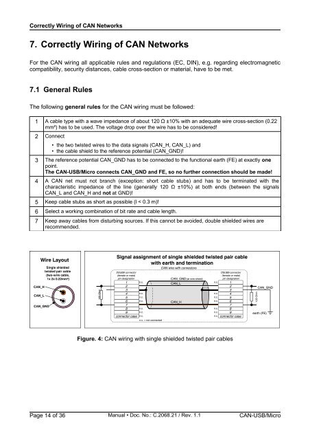
Wire Layout<br />
<strong>CAN</strong>_GND<br />
Single shielded<br />
twisted pair cable<br />
(two-wire cable,<br />
1x 2x 0.22mm²)<br />
120 Ohm<br />
Signal assignment of single shielded twisted pair cable<br />
with earth and termination<br />
<strong>CAN</strong> wire with connectors<br />
DSUB9 connector<br />
DSUB9 connector<br />
(female or male)<br />
(female or male)<br />
pin designation<br />
<strong>CAN</strong>_GND (at wire shield)<br />
pin designation<br />
1<br />
2<br />
n.c.<br />
<strong>CAN</strong>_L<br />
n.c. 1<br />
2<br />
3<br />
3<br />
4 n.c.<br />
n.c. 4<br />
5 n.c.<br />
n.c. 5<br />
6<br />
7<br />
n.c.<br />
<strong>CAN</strong>_H<br />
n.c. 6<br />
7<br />
8 n.c.<br />
n.c. 8<br />
9 n.c.<br />
n.c. 9<br />
connector case n.c.<br />
n.c. = not connected<br />
n.c. connector case<br />
Figure. 4: <strong>CAN</strong> wiring with single shielded twisted pair cables<br />
<strong>CAN</strong>_GND<br />
Page 14 of 36 <strong>Manual</strong> • Doc. No.: C.2068.21 / Rev. 1.1 <strong>CAN</strong>-<strong>USB</strong>/<strong>Micro</strong><br />
120 Ohm<br />
earth (FE)


