

Download CAN-USB-Micro Hardware Manual - esd electronics, Inc.
Download CAN-USB-Micro Hardware Manual - esd electronics, Inc.
Download CAN-USB-Micro Hardware Manual - esd electronics, Inc.

Create successful ePaper yourself
Turn your PDF publications into a flip-book with our unique Google optimized e-Paper software.
<strong>CAN</strong>-Bus Troubleshooting Guide<br />
Normally the voltage should be between 2.0 V and 4.0 V.<br />
If it is lower than 2.0 V or higher than 4.0 V, it is possible that one or more nodes have faulty<br />
transceivers. For a voltage lower than 2.0 V please check <strong>CAN</strong>_H and <strong>CAN</strong>_L conductors for<br />
continuity. For a voltage higher than 4.0 V, please check for excessive voltage.<br />
To find the node with a faulty transceiver please test the <strong>CAN</strong> transceiver resistance (see next<br />
page).<br />
8.5 <strong>CAN</strong> Transceiver Resistance Test<br />
<strong>CAN</strong> transceivers have one circuit that controls <strong>CAN</strong>_H and another circuit that controls <strong>CAN</strong>_L.<br />
Experience has shown that electrical damage to one or both of the circuits may increase the<br />
leakage current in these circuits.<br />
To measure the current leakage through the <strong>CAN</strong> circuits, please use an resistance measuring<br />
device and:<br />
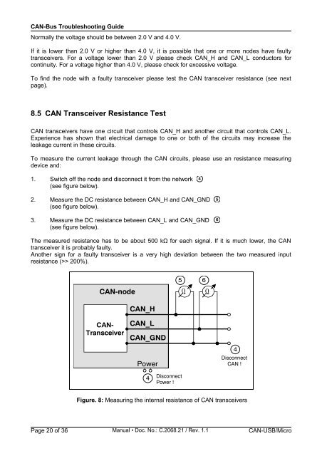
1. Switch off the node and disconnect it from the network<br />
(see figure below).<br />
2. Measure the DC resistance between <strong>CAN</strong>_H and <strong>CAN</strong>_GND<br />
(see figure below).<br />
3. Measure the DC resistance between <strong>CAN</strong>_L and <strong>CAN</strong>_GND<br />
(see figure below).<br />
The measured resistance has to be about 500 kΩ for each signal. If it is much lower, the <strong>CAN</strong><br />
transceiver it is probably faulty.<br />
Another sign for a faulty transceiver is a very high deviation between the two measured input<br />
resistance (>> 200%).<br />
<strong>CAN</strong>-node<br />
<strong>CAN</strong>-<br />
Transceiver<br />
<strong>CAN</strong>_H<br />
<strong>CAN</strong>_L<br />
<strong>CAN</strong>_GND<br />
Power<br />
4<br />
Disconnect<br />
Power !<br />
Figure. 8: Measuring the internal resistance of <strong>CAN</strong> transceivers<br />
Page 20 of 36 <strong>Manual</strong> • Doc. No.: C.2068.21 / Rev. 1.1 <strong>CAN</strong>-<strong>USB</strong>/<strong>Micro</strong><br />
4<br />
5 6<br />
Ω<br />
Ω<br />
5<br />
6<br />
4<br />
Disconnect<br />
<strong>CAN</strong> !


