Manual tehnic automate cafea Saeco Group 500
Manual tehnic automate cafea Saeco Group 500
Manual tehnic automate cafea Saeco Group 500

You also want an ePaper? Increase the reach of your titles
YUMPU automatically turns print PDFs into web optimized ePapers that Google loves.
Automatic beverage vending machine<br />
<strong>Saeco</strong> <strong>Group</strong> <strong>500</strong> NEW<br />
Model:<br />
Model:<br />
ESPRESSO<br />
ESPRESSO PLUS<br />
<br />
TYPE: SG<strong>500</strong>N<br />
OPERA OPERATION OPERA TION AND AND MAINTENANCE<br />
MAINTENANCE
English<br />
2<br />
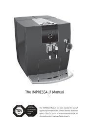
MAIN PARTS<br />
10<br />
1 Brew group and coffee grinder<br />
2 Vending machine unit<br />
3 Sugar dispensing unit<br />
4 Electronic card<br />
5 Cup dispenser<br />
6 Coiner unit<br />
7 Tray socket<br />
8 Data plate<br />
9 Data plate showing the minimum and<br />
maximum water pressure<br />
10 Water mains connection<br />
7<br />
9<br />
8<br />
3<br />
2<br />
6<br />
4<br />
5<br />
1
TABLE OF CONTENTS<br />
1 - INTRODUCTION TO<br />
THE MANUAL...................... 4<br />
1.1 Foreword ............................................ 4<br />
1.2 Symbols used .................................... 4<br />
1.3 General instructions ........................... 5<br />
1.4 Operator requirements ....................... 7<br />
2 - TECHNICAL SPECIFICATIONS.7<br />
3 - SAFETY STANDARDS............ 8<br />
3.1 Foreword ............................................ 8<br />
3.2 General safety rules ........................... 8<br />
4 - HANDLING AND STORAGE.. 9<br />
4.1 Handling and transport ....................... 9<br />
4.2 Storage .............................................. 10<br />
4.3 Packaging .......................................... 10<br />
5 - GENERAL TECHNICAL<br />
DESCRIPTION ..................... 11<br />
5.1 Permitted use .................................... 11<br />
5.2 Models ............................................... 11<br />
5.3 Basic operating concepts ................... 11<br />
6 - INSTALLATION .................... 14<br />
6.1 Positioning ......................................... 14<br />
6.2 Receipt .............................................. 15<br />
6.3 Unpacking .......................................... 15<br />
6.4 Water mains connection .................... 17<br />
6.5 Electric mains connection .................. 17<br />
6.6 Machine start-up ................................ 18<br />
6.7 Installation ......................................... 19<br />
6.7.1 Cleaning and filling of resin-based water<br />
softener............................................19<br />
6.7.2 Water circuit filling ............................. 20<br />
6.7.3 Cleaning the parts in contact with<br />
foodstuffs..........................................21<br />
6.8 Product loading .................................. 22<br />
6.8.1 Container loading ............................... 22<br />
6.8.2 Label insertion ................................... 23<br />
6.8.3 Cup loading ........................................ 23<br />
6.8.4 Stirrer loading..................................... 24<br />
6.8.5 Grounds bag insertion ........................ 25<br />
6.8.6 Payment system installation .............. 26<br />
7 - PROGRAMMING................. 27<br />
English<br />
7.1 Machine software updating through eprom...31<br />
7.2 Description of functions ...................... 31<br />
8 - SERVICE .............................. 39<br />
9 - MAINTENANCE ................... 41<br />
9.1 Cleaning and Loading ......................... 41<br />
9.1.1 Daily cleaning .................................... 41<br />
9.1.2 Weekly cleaning ................................ 42<br />
9.1.3 Product loading .................................. 43<br />
9.2 Maintenance ...................................... 43<br />
9.2.1 Scheduled and unscheduled maintenance.. 44<br />
9.2.2 Brew group maintenance .................... 44<br />
9.3 Adjustments ...................................... 45<br />
9.3.1 Dose and grinding adjustment ............ 45<br />
9.4 Resin regeneration (where the water<br />
softener is provided) ........................... 46<br />
10 - INACTIVITY ......................... 47<br />
11 - DISMANTLING .................... 48<br />
12 - TROUBLESHOOTING GUIDE<br />
FOR THE MOST COMMON<br />
FAILURES OR ERRORS ........ 49<br />
3
English<br />
4<br />
1 - INTRODUCTION<br />
TO THE MANUAL<br />
1.1 Foreword<br />
Important<br />
This publication is an integral part of the vending<br />
machine and shall be read carefully in order to<br />
use it in a correct way. Complying with safety<br />
requirements is also essential.<br />
This manual contains the technical information<br />
necessary to correctly carry out the procedures<br />
of operation, cleaning, installation and<br />
maintenance of the vending machine SG<strong>500</strong>NE.<br />
Always refer to this publication before carrying<br />
out any operation.<br />
Manufacturer: SAECO International <strong>Group</strong><br />
Via Panigali, 39 - 40041 Gaggio Montano (BO).<br />
This manual shall be kept with care and shall go<br />
with the machine throughout its operational life,<br />
also during changes of ownership.<br />
If this manual should be lost or worn out, it is<br />
possible to require another copy to the<br />
Manufacturer or to an Authorized Service Centre.<br />
In this event, please indicate the data on the plate<br />
located on the rear part of the machine.<br />
1.2 Symbols used<br />
A number of symbols are used in this manual to<br />
indicate dangerous situations that require various<br />
degrees of expertise.<br />
The symbol is integrated with a message<br />
suggesting operating procedures or behaviours<br />
and providing useful information concerning the<br />
good operation of the vending machine.<br />
Warning<br />
This symbol indicates dangerous situations for<br />
the users, supply operators and maintenance<br />
technicians dealing with either the vending<br />
machine or the product to be dispensed.<br />
Important<br />
This symbol indicates operations that keep the<br />
machine in good working conditions, if properly<br />
carried out.<br />
Recommended solutions<br />
The symbol indicates the procedures that make<br />
the programming and/or maintenance<br />
operations quicker.<br />
User<br />
This symbol indicates the user of the vending<br />
machine. This person is not authorized to carry<br />
out any cleaning or maintenance operation.<br />
Supply operator<br />
It is used to indicate operations to be exclusively<br />
carried out by personnel in charge of the vending<br />
machine supply and cleaning.<br />
Maintenance operations that require a<br />
maintenance technician are not to be performed<br />
by the supply operator.<br />
Maintenance technician<br />
It is used to indicate operations to be performed<br />
by specialized maintenance technicians only.<br />
He is the only person authorized to keep the KEY<br />
TO ACTIVATE THE SAFETY MICROSWITCH<br />
which allows disabling the security systems.
Read<br />
This symbol indicates that the user should read<br />
the instruction manual carefully before operating<br />
the machine.<br />
1.3 General instructions<br />
Warning<br />
Before using the vending machine, read this<br />
manual carefully. A good knowledge of the<br />
information and instructions contained in this<br />
document is essential to use correctly the<br />
vending machine and comply with safety<br />
requirements.<br />
Warning<br />
For no reason whatsoever shall the supply<br />
operator access those parts of the machine that<br />
are protected by guards requiring special<br />
instruments for their removal.<br />
Some maintenance operations (to be carried out<br />
solely by specialised technicians) expressly<br />
require that certain safety devices are switched<br />
off.<br />
Knowledge and absolute respect, from a<br />
technical point of view, of the safety standards<br />
and danger warnings contained in this manual,<br />
are fundamental for installing, using, servicing<br />
and maintaining the machine under conditions<br />
of minimum risk.<br />
• The operator of the vending machine has only<br />
to carry out those operations he has been<br />
trained for, as far as it falls within his<br />
competence .<br />
The user shall have a good knowledge of all<br />
operating mechanisms of the machine as far<br />
as it falls within his competence.<br />
English<br />
• It is the buyer's responsibility to ascertain that<br />
the machine operators have been trained and<br />
informed of all the indications and<br />
specifications contained in the documentation<br />
supplied. Even so, the operator shall be<br />
aware of the potential risks that exist while<br />
operating the automatic vending machine.<br />
• Operating reliability and the efficiency of the<br />
machine performance are guaranteed only if<br />
original spare parts are used.<br />
• The user will be held entirely responsible for<br />
any modification he may apply to the machine.<br />
All the operations necessary in order to<br />
maintain the machine in good working order,<br />
before and during use, are to the charge of<br />
the operator.<br />
• Tampering with or modifications made to the<br />
machine not previously authorized by the<br />
manufacturer, release the latter from any<br />
liability for damage deriving from, or referable<br />
to the above mentioned modifications.<br />
• This manual reflects the state of the art of<br />
the automatic vending machine at the<br />
moment of the issue on the market; possible<br />
modifications, improvements or adjustments<br />
that are made to machines that are<br />
subsequently marketed, do not oblige the<br />
SAECO International <strong>Group</strong> either to<br />
intervene on the previously supplied machine<br />
or consider it and the relevant manual to be<br />
defective or inadequate.<br />
5
English<br />
• However, the SAECO International <strong>Group</strong> is<br />
entitled, when it deems it expedient for valid<br />
reasons, to update the manuals already<br />
present on the market and send revised<br />
information sheets to their customers which<br />
shall be kept together with the original manual.<br />
Any technical problems that may arise can<br />
easily be solved by consulting this manual.<br />
For further information, contact the dealer<br />
where the machine was purchased, or one<br />
of the authorized service centres.<br />
When calling, please, give the following<br />
information:<br />
- the data registered on the Data plate located<br />
on the rear part of the v. m. (fig. 1)<br />
6<br />
fig. 1<br />
fig. 2<br />
Data Plate<br />
- the version of program resident in the<br />
microprocessor - see the adhesive label on<br />
the component mounted on the C.P.U. board<br />
(ref. '1', fig. 2) or, if possible, the version of<br />
program shown on the machine display when<br />
button 2 is pressed on the CPU board to<br />
activate the 'Service' mode (fig. 41).<br />
- the board code appearing on the welding side<br />
of the C.P.U. board.<br />
Warning<br />
It is absolutely forbidden to tamper with or modify<br />
the data plate.<br />
The SAECO International <strong>Group</strong> declines all<br />
responsibility for injury caused to people or<br />
damage caused to things as a consequence of:<br />
- incorrect installation<br />
- inappropriate electrical and/or water<br />
connection<br />
- inadequate cleaning and maintenance<br />
- unauthorized modification<br />
- improper use of the vending machine<br />
- non-original spare parts<br />
• In no event will the SAECO International<br />
<strong>Group</strong> be obliged to indemnify any damage<br />
caused as a result of the forced inactivity of<br />
the machine due to failure.<br />
• Installation and maintenance operations shall<br />
exclusively be performed by qualified<br />
technicians.<br />
• Use only specific foodstuffs for use in<br />
automatic vending machines.<br />
• The automatic vending machine is not<br />
suitable for outside installation. The machine<br />
shall be installed in dry places, with<br />
temperatures not lower than 1°C and it shall<br />
not be installed in places where cleaning is<br />
done with water hoses (e.g. large kitchens …).<br />
• If at the time of installation, the usage<br />
conditions are different from those<br />
established or are subject to change over<br />
time, please contact the manufacturer<br />
immediately before using the machine.<br />
Furthermore, always act in compliance with<br />
national or local standards.
1.4 Operator requirements<br />
To guarantee the safety of the machine three<br />
operators with different skills are required:<br />
User<br />
Access to the inside of the machine is forbidden<br />
to the user.<br />
Supply operator<br />
The safekeeping of the access key to the inside<br />
of the machine is entrusted to the Supply<br />
operator by the Maintenance Technician. He has<br />
the task of supplying the products, external<br />
cleaning, activating and stopping the machine.<br />
Warning<br />
The Supply Operator is not authorized to carry<br />
out operations that are indicated as competency<br />
of the Maintenance technician in this publication.<br />
Maintenance technician<br />
The only person authorized to intervene and start<br />
the programming procedures, adjust, set up and<br />
upkeep the machine.<br />
2 - TECHNICAL<br />
SPECIFICATIONS<br />
mm. 670<br />
fig. 3<br />
mm. 600<br />
English<br />
Weight from 90 to 105 Kg<br />
Overall dimensions See fig. 3<br />
Power consumption See<br />
Data<br />
Plate (fig.1)<br />
Power supply voltage See<br />
Data<br />
Plate (fig.1)<br />
Electric voltage frequency See<br />
Data<br />
Plate (fig.1)<br />
Power cord length 1600 mm<br />
Water mains connection 3/8 gas<br />
Water mains pressure from 1.5 to 8<br />
bars (fig.4)<br />
mm. 1700<br />
7
English<br />
8<br />
fig. 4<br />
Data plate showing the minimum<br />
and maximum water pressure<br />
CUP DISPENSER<br />
Suitable for cups with 70-71 mm dia.<br />
BOILER HEATING ELEMENTS<br />
Armoured type:<br />
from 1000 Watts for coffee boiler<br />
CONTAINER CAPACITY<br />
Coffee beans Kg 4,0<br />
Instant coffee Kg 0,6<br />
Granular milk Kg 2,1<br />
Chocolate Kg 4,3<br />
Tea Kg 5,9<br />
Soup Kg 5,5<br />
Sugar Kg 4,2<br />
Cups <strong>500</strong><br />
Stirrers <strong>500</strong><br />
3 - SAFETY STANDARDS<br />
3.1 Foreword<br />
In compliance with the Machine Directive 98/37/<br />
EEC, Low Tension Directive 73/23/EEC and CE<br />
Marking Directive 93/68/EEC, the SAECO<br />
International <strong>Group</strong> has drawn up a technical file<br />
on D.A. SG<strong>500</strong>NE vending machine at its plants,<br />
acknowledging during the design phase the rules<br />
indicated in the Declaration of Conformity<br />
included in the vending machine documentation.<br />
3.2 General safety rules<br />
Warning<br />
- Before using the vending machine, read this<br />
manual carefully.<br />
- Installation and maintenance operations shall<br />
exclusively be performed by qualified<br />
technicians.<br />
- For no reason whatsoever shall the operator<br />
access those parts of the machine that are<br />
protected by guards requiring special<br />
instruments for their removal.<br />
- Good knowledge and absolute respect, from<br />
a technical point of view, of the safety<br />
standards and danger warnings contained in<br />
this manual, are fundamental for installing,<br />
using, servicing and maintaining the machine<br />
in conditions of minimum risk.<br />
Always disconnect the POWER CABLE before<br />
maintenance or cleaning activities.<br />
Do not, under no circumstances, intervene on<br />
the machine or remove safety guards before hot<br />
parts have cooled!
- Operating reliability and the efficiency of the<br />
machine performance are guaranteed only if<br />
original spare parts are used.<br />
- The automatic vending machine is not<br />
suitable for outside installation. The machine<br />
shall be installed in dry places, with<br />
temperatures not lower than 1°C and it shall<br />
not be installed in places where cleaning is<br />
done with water hoses (e.g. large kitchens…).<br />
- In order to guarantee the performance of the<br />
machine, always keep the automatic vending<br />
machine in perfect cleaning conditions.<br />
- The SAECO International <strong>Group</strong> declines all<br />
responsibility for injury caused to people or<br />
damage caused to things as a consequence<br />
of:<br />
• incorrect installation<br />
• inappropriate electrical and/or water<br />
connection<br />
• inadequate cleaning and maintenance<br />
• unauthorized modification<br />
• improper use of the vending machine<br />
• non-original spare parts<br />
- Furthermore, always act in compliance with<br />
national or local standards.<br />
4 - HANDLING AND<br />
STORAGE<br />
4.1 Handling and transport<br />
(fig. 5)<br />
fig. 5<br />
English<br />
The transport of the vending machine shall be<br />
carried out by skilled personnel.<br />
The vending machine is delivered on a pallet;<br />
for handling purposes use a fork lift truck and<br />
move it slowly in order to avoid any possible<br />
overturning or dangerous oscillations.<br />
Avoid:<br />
Important<br />
- lifting the vending machine with ropes or<br />
presses<br />
- dragging the vending machine<br />
- turning over or laying the vending machine<br />
down during transport<br />
- jolting the vending machine<br />
9
English<br />
With regard to the vending machine, avoid :<br />
- bumping it<br />
- overloading it with other packages<br />
- exposing it to rain, cold weather or heat<br />
sources<br />
- keeping it in damp places<br />
4.2 Storage<br />
In the event of storage, avoid any overlapping of<br />
several machines, keep them in a vertical<br />
position, in dry places with temperatures not<br />
lower than 1°C.<br />
10<br />
fig. 6<br />
4.3 Packaging<br />
The vending machine is protected by polystyrene<br />
angles and by a transparent polypropylene film<br />
(fig.6).<br />
The automatic vending machine will be delivered<br />
packaged, assuring both a mechanical guard<br />
and protection against damage from any<br />
environmental agents.<br />
Labels are applied on the packaging, indicating:<br />
- handle with care<br />
- do not turn upside-down<br />
- protect from rain<br />
- do not overlap<br />
- protect from heat sources<br />
- not shock resistant<br />
- type of vending machine and serial number<br />
Important<br />
When the transport is over, the packaging shall<br />
be undamaged, which means it shall not:<br />
- show any dent, sign of shocks, distortions or<br />
breakages to the external packaging<br />
- show wet parts or signs that could lead to<br />
suppose that the packaging has been<br />
exposed to rain, freezing weather or heat<br />
- show signs of tampering
5 - GENERAL TECHNICAL<br />
DESCRIPTION<br />
5.1 Permitted use<br />
The vending machine is to be used exclusively<br />
for the dispensing of beverages, prepared by<br />
mixing foodstuffs with water - by brewing for<br />
coffee).<br />
For this purpose, use products that the<br />
manufacturer has declared suitable for the<br />
automatic distribution in open containers.<br />
Beverages are brewed in appropriate plastic cups<br />
automatically dispensed by the machine. The<br />
sugar stirrer is automatically dispensed.<br />
The beverages shall be drunk immediately and<br />
under no circumstances shall they be kept for<br />
subsequent consumption.<br />
5.2 Models<br />
The following terminology is used so as to<br />
distinguish the various models of automatic<br />
vending machines:<br />
SAECO GROUP <strong>500</strong>N E :<br />
version equipped with a plastic brew group, 4<br />
instant products and 48 mm grinders.<br />
SAECO GROUP <strong>500</strong>N E PLUS:<br />
version equipped with a plastic brew group, 4<br />
instant products and 64 mm grinders.<br />
Warning:<br />
This manual refers to the top-of-the -range<br />
model: it is therefore possible to find descriptions<br />
or explanations not relating to the machine you<br />
have.<br />
5.3 Basic operating concepts<br />
English<br />
During normal functioning, the vending machine<br />
is in standby. By introducing the necessary<br />
amount, according to the preset price, and<br />
pressing the key relating to the desired beverage,<br />
a beverage dispensing cycle is activated. It can<br />
be divided in different processes:<br />
CUP DISPENSING<br />
• This is the first operation that the vending<br />
machine activates - except for 'without cup'<br />
dispensing selection.<br />
• The motor that engages the nozzle support<br />
is actuated to retract the support and let the<br />
cup drop into the dispensing outlet.<br />
• The motor inside the cup dispenser moves<br />
the scrolls in order to separate and let the<br />
cup fall into the special support fork inside<br />
the dispensing outlet.<br />
11
English<br />
SUGAR AND STIRRER DISPENSING<br />
Where provided for and required, a preset<br />
maximum dose of sugar is dispensed, with the<br />
possibility to stop the machine when the required<br />
dose has been reached.<br />
Dispensing is divided in the following phases:<br />
• the dragging motor of the channel is engaged<br />
and conveys the sugar into the cup.<br />
• the gearmotor activates the sugar container<br />
screw, dispensing the desired quantity of<br />
product into the conveyor tube.<br />
• the solenoid is activated, and the stirrer is<br />
directly dispensed into the cup through a<br />
special channel (fig.9).<br />
12<br />
INSTANT BEVERAGES<br />
This process takes place only after the<br />
dispensing of the cup, the sugar and the stirrer.<br />
According to the beverage selected and the<br />
model of the vending machine the following<br />
processes are enabled for the beverage brewing.<br />
model of the vending machine the following<br />
processes are enabled for the beverage brewing.<br />
• If fitted, the motor mixer is engaged.<br />
• The solenoid valve for instant products (ref.<br />
'1' fig.7), installed on the coffee boiler, is<br />
engaged and conveys the programmed<br />
quantity of water into the mixer. Then, the<br />
pump (ref. '2' fig. 7) is engaged and, controlled<br />
by a special electronic device (volumetric<br />
counter ref. '3' fig. 7), it dispenses the<br />
programmed quantity of water.<br />
fig. 7<br />
• The gearmotor of the instant product engages<br />
the screw container, dispensing the desired<br />
quantity of product into the mixer.<br />
• Once the preset quantity of water and powder<br />
is dispensed, the mixer is disconnected.
ESPRESSO COFFEE<br />
This process takes place only after the<br />
dispensing of the cup, the sugar and the stirrer.<br />
• the grinder (ref. 1 fig.8) is engaged and runs<br />
until the ground coffee dose set by the dosing<br />
unit (ref 2 fig.8) is reached.<br />
fig.8<br />
• the electromagnet of the dosing unit (ref. '3'<br />
fig.8) controls the door opening and the<br />
subsequent falling of the coffee into the<br />
brewing cup.<br />
fig.9<br />
• the group rotation gearmotor moves the group<br />
onto the brewing position and compresses<br />
the coffee tablet (fig.9).<br />
fig.7<br />
English<br />
• controlled by the appropriate electronic device<br />
(volumetric counter - ref. '3' fig.7), the pump<br />
dispenses the preset quantity of water sucked<br />
from the coffee boiler.<br />
• the brew group gearmotor goes back to its rest<br />
position while the used coffee tablet is ejected.<br />
According to the type of program set (see<br />
programming menu), the above procedure for<br />
the grinder and dosing unit engagement can take<br />
place in reverse.<br />
13
English<br />
14<br />
6 6 - - INST INSTALLA<br />
INST ALLA ALLATION<br />
ALLA TION<br />
6.1 Positioning<br />
The vending machine is not suitable for outside<br />
installation. It shall be installed in dry places, with<br />
temperatures not lower than 1°C. Furthermore<br />
it shall not be installed in places where cleaning<br />
is done with water hoses or where there is the<br />
danger of explosions or fires.<br />
- If positioned near a wall, there shall be a<br />
minimum distance of at least 5 cm from the<br />
wall (fig. 10), so as to allow regular ventilation.<br />
Under no circumstances cover the vending<br />
machine with cloths or similar.<br />
fig.10
- Position the vending machine, checking the<br />
levelling by means of the adjustable feet<br />
already assembled on the machine (fig.11).<br />
Make sure that the vending machine does not<br />
have an inclination exceeding 2 degrees.<br />
fig.11<br />
The SAECO International <strong>Group</strong> declines all<br />
responsibility for inconveniences due to the<br />
failure in observing the above mentioned<br />
installation rules.<br />
If installation takes place in safety evacuation<br />
corridors, make sure that the machine with the<br />
door open assure sufficient space for people to<br />
pass by (fig. 10).<br />
In order to avoid the floor to get dirty as a result<br />
of accidental spillage of products, use, if<br />
necessary, a sufficiently wide protecting device<br />
to cover the operating area under the vending<br />
machine.<br />
6.2 Receipt<br />
Upon receipt of the automatic vending machine,<br />
it is necessary to check it has not suffered<br />
damage during transport. If damage of any kind<br />
is noticed, immediately place a claim with the<br />
forwarder.<br />
An envelope is supplied with the vending<br />
machine, called 'CUSTOMER KIT', containing<br />
the objects shown in Fig. 12.<br />
fig.12<br />
fig.13<br />
- Instruction booklet.<br />
- Powder tank plates and prices in<br />
euro.<br />
- Pushbutton panel selection<br />
labels.<br />
- Instruction labels.<br />
- Wiring and hydraulic diagram.<br />
- Power cord.<br />
- Safety micro key<br />
(Maintenance technician).<br />
- Declaration of conformity.<br />
6.3 Unpacking<br />
English<br />
- Free the vending machine from the packaging,<br />
cutting the protective film in which it is wrapped,<br />
along one of the protection angles (fig.13).<br />
15
English<br />
- Remove the vending machine from the pallet,<br />
unscrewing the screws that secure it to the<br />
pallet (fig.14).<br />
16<br />
fig.14<br />
- Remove the key from the beverage<br />
dispensing outlet (fig.15).<br />
fig.15<br />
Open the door of the vending machine and<br />
remove the adhesive tape from the components.<br />
- Remove the polystyrene fixing the product<br />
containers (fig. 16).<br />
fig.16<br />
Warning:<br />
The packing material shall not be accessible to<br />
unauthorized people, as it is a potential source<br />
of danger. For the disposal please contact<br />
qualified companies.
6.4 Water mains connection<br />
Before connecting the vending machine to the<br />
water mains, make sure the water:<br />
- is drinking (if possible by means of test<br />
laboratory certification)<br />
- has a pressure ranging between 1.5 bars<br />
and 8 bars, otherwise use a pump or a water<br />
pressure reducer accordingly<br />
- if not already fitted, install a tap in an<br />
accessible position, so as to separate the<br />
equipment from the water mains, should it<br />
be necessary (fig.17).<br />
fig.18<br />
fig.17<br />
- let some water flow out of the tap so that to<br />
eliminate possible traces of impurities and dirt<br />
(fig. 18).<br />
fig.19<br />
English<br />
- connect the tap to the vending machine, using<br />
a copper or nylon pipe, suitable for foodstuffs<br />
and for the purpose of bearing the water<br />
supply pressure. should a flexible hose be<br />
used, it is necessary to assemble the<br />
reinforcement bearing inside, supplied with<br />
the machine.<br />
- The connection provided for is a 3/8 gas-type<br />
fitting.<br />
6.5 Electric Mains connection<br />
The vending machine is designed to operate with<br />
single phase voltage at 230 Volts and is protected<br />
by 8A rapid fuses.<br />
We suggest checking the following:<br />
- the mains voltage of 230 V shall not exceed<br />
a ± 6% fluctuation;<br />
- the power supply must be suitable to the<br />
machine.<br />
- a diversified protection system shall be<br />
connected<br />
The machine shall be earthed in observance with<br />
operating safety rules in force.<br />
For this reason, verify the system earth wire<br />
connection to ascertain that it is efficient and in<br />
compliance with national and European electric<br />
safety standards.<br />
If necessary, have the system inspected by<br />
qualified personnel.<br />
- The vending machine is provided with a power<br />
cord (fig. 19)<br />
17
English<br />
- The sockets that are not compatible with the<br />
plug of the machine shall be replaced.<br />
- The use of extensions, adapters and/or multiple<br />
plugs is forbidden (fig. 20).<br />
18<br />
fig.20<br />
6.6 Machine start-up<br />
The machine is equipped with two safety<br />
switches (fig. 21/23) which disconnect the<br />
utilities whenever the door or the top door are<br />
opened - see wiring diagram.<br />
fig.21<br />
Safety switch<br />
Warning<br />
During the setting-up phase, before powering up<br />
the machine, make sure you have connected it<br />
to the water mains and opened the water tap.<br />
Warning<br />
The power cable plug (ref. ‘1’, fig. 22), as well as<br />
the service switch inside the vending machine<br />
(ref. ‘1’, fig. 23) and the safety switches remain<br />
live (fig. 21/23).<br />
fig.22<br />
fig.23<br />
“1”<br />
Safety switch<br />
- It is however necessary to operate with the<br />
door open but the vending machine connected<br />
to the mains for some operations.<br />
Skilled technicians may operate in this way, by<br />
inserting the special plastic key, supplied with<br />
the machine, into the door switch, turning it of<br />
90° (fig. 21).
Warning<br />
The opening and possible switching on of the<br />
machine with the door open shall only be<br />
performed by authorized and technically qualified<br />
personnel. Do not leave the machine unattended<br />
while it is open.<br />
Give the key to qualified and authorized<br />
personnel only.<br />
Whenever the machine is switched on a test<br />
cycle is performed in order to verify the correct<br />
position of the moving parts and the presence<br />
of water and other products.<br />
6.7 Installation<br />
Important:<br />
When switched on, the machine automatically<br />
fills the water circuit and the related boilers. For<br />
a correct automatic installation in case of a water<br />
softener system being used, it is necessary that<br />
the latter is completely filled with water and<br />
properly relieved of any air bubbles.<br />
6.7.1 Cleaning and filling of resinbased<br />
water softener<br />
Before installing the water softener in the<br />
machine and using it, it is advisable to clean the<br />
resins and fill the water softener. Therefore,<br />
install the water softener already filled with water<br />
and cleaned. If you wish to carry out this<br />
operation directly in the machine, act as follows:<br />
- in the OPTION menu, disable the selfinstallation<br />
- insert the pipe of the bottom tap into a<br />
container suitable for this purpose<br />
fig.24<br />
fig.25<br />
English<br />
- open the bottom tap (fig. 24) and the upper<br />
cap of the water softener so as to remove<br />
the air bubble.<br />
- insert the key in the door switch (fig.21)<br />
- let the water softener fill up completely and<br />
remove the key from the door switch<br />
- close the upper cap<br />
- insert the key once again in the door switch<br />
- let the water flow out of the drain tube until it is<br />
clear (fig. 25)<br />
- remove the key and close the tap<br />
19
English<br />
6.7.2 Water circuit filling<br />
First the machine fills the instant product boiler,<br />
if any, and the water tank. Then it fills the<br />
espresso coffee boiler by performing two<br />
brewings of long coffee automatically.<br />
20<br />
Important:<br />
Before powering the machine on and thus<br />
proceeding with the automatic installation:<br />
1. Make sure that the water softener is filled with<br />
water and the air bubbles removed.<br />
2. Fill with coffee beans the appropriate<br />
container; this is necessary as the machine<br />
will perform automatically a few brewings to<br />
fill the boiler.<br />
3. Load at least the central column of the cup<br />
basket.<br />
NOTE:<br />
If the filling of the boiler is not successful, the<br />
machine cannot be set into service. The<br />
'installation failed' message on the display will<br />
be shown. Should it be the case, eliminate the<br />
trouble and repeat the automatic installation,<br />
after repairing the trouble (Section 8 - SERVICE,<br />
failure repair).<br />
After carrying out the DIAGNOSIS phase, the<br />
machine fills the water circuit of the float tank<br />
and the brew group boiler in a fully automatic<br />
mode. In this phase, the heating resistances of<br />
the boilers are automatically switched off. When<br />
the machine detects that boilers are loaded, it<br />
automatically proceeds to the HEATING phase.<br />
The sequence of operations will be:<br />
- insert the special key in the door switch<br />
- at machine start-up, the water tank with float<br />
automatically starts to fill up, while the<br />
machine carries out the automatic diagnosis.<br />
During the diagnosis, the following components<br />
are engaged:<br />
- the brew group, to ensure the right initial<br />
position.<br />
- the cup basket to load the first column of<br />
cups in the release device.<br />
Then, during the initialisation phase:<br />
- the water tank and the instant product boiler,<br />
if any, fill up<br />
- 2 complete brewings of very long coffee are<br />
performed automatically in order to fill the<br />
brew group boiler.<br />
- once the water circuit filling is completed, the<br />
heating phase starts and the boiler heating<br />
resistances automatically switch on.
fig.26<br />
Warning<br />
IMPORTANT: When the boilers are<br />
completely filled, carry out several cleanings of<br />
the mixers, in order to remove possible residues<br />
from the water circuits.<br />
N.B.: to enable dispensing tests or cleanings,<br />
see the use of the pushbutton panel in ‘Service’<br />
mode (fig.26).<br />
“SERVICE”<br />
- After performing these operations, wait about<br />
ten minutes until the operating temperatures<br />
are reached.<br />
fig.27<br />
fig.28<br />
English<br />
6.7.3 Cleaning the parts in contact<br />
with foodstuffs<br />
Wash all the v.m. parts in contact with foodstuffs.<br />
- wash your hands carefully.<br />
- prepare a chlorine based anti-bacterial<br />
cleaning solution - it can be purchased at<br />
chemists - following the concentrations given<br />
on the product instruction label.<br />
- remove all the product containers from the<br />
vending machine (fig.27).<br />
- remove container lids and product channels<br />
(fig.28). Immerse all items into the previously<br />
prepared solution.<br />
21
English<br />
- remove all the instant product channels, water<br />
funnels, mixing bowls and impellers and<br />
silicone tubes; also immerse these parts in<br />
the prepared solution (fig.29).<br />
22<br />
1 2<br />
fig.29<br />
fig.30<br />
3<br />
- with a cloth soaked with the solution clean<br />
the mixer assembly base (fig.30)<br />
- the parts shall be left to soak in the solution<br />
for the amount of time indicated on the<br />
instruction label.<br />
- recover all the parts, rinse them thoroughly,<br />
dry them perfectly and proceed with their reassembly<br />
on the machine.<br />
Warning<br />
For further safety, after reassembling the parts, perform<br />
some automatic cleaning cycles so as to eliminate<br />
possible residues.<br />
6.8 Product loading<br />
6.8.1 Container loading<br />
- product containers can be loaded without<br />
taking them out of their housings; should it<br />
be necessary to take them out, close the<br />
sliding door that is mounted on the product<br />
channel outlet (fig.27). Especially in case of<br />
coffee beans, the sliding door of the hopper<br />
must be closed before removing the<br />
container.<br />
fig.27<br />
N.B.: containers can be loaded without being<br />
removed from their supports.<br />
- Lift the lid of each container and load the<br />
product (fig.31)<br />
fig.31
- Make sure there are no lumps; do not<br />
compress the product nor use an excessive<br />
quantity as to avoid ageing of the product<br />
itself. We suggest filling the containers with<br />
the quantity of product needed for the<br />
consumption estimated within two<br />
subsequent loadings.<br />
Refer to the TECHNICAL SPECIFICATIONS<br />
section to check each container capacity.<br />
fig.32<br />
Warning<br />
- Before using the machine, to ensure the<br />
proper operation of the container with<br />
orientable duct, perform 3 - 4 brewings to fill<br />
the channel.<br />
- Once the sugar container is filled, make sure<br />
the panel is properly reassembled, by<br />
checking the click located on one side.<br />
6.8.2 Label insertion<br />
- The labels indicating the product selections<br />
shall be inserted in the special slots according<br />
to the order shown in figure 42.<br />
Perform the operation as follows:<br />
- remove the cup column (fig. 32)<br />
- insert labels following to the order shown and<br />
according to the selections used by the<br />
machine (fig.33)<br />
- reassemble the cup column<br />
fig.33<br />
6.8.3 Cup loading<br />
fig.34<br />
English<br />
Use only cups conceived for automatic vending<br />
machines, with a diameter of 70-71 mm, do not<br />
compress the cups together while loading.<br />
Important: DO NOT TRY TO ROTATE<br />
THE CUP COLUMN MANUALLY.<br />
During installation phase with the cup dispenser<br />
completely empty, operate as follows:<br />
- before powering the vending machine, load a<br />
column of cups, as long as it is not the one<br />
relevant to the dispensing ring (fig.34)<br />
23
English<br />
- insert the key in the door switch (see fig.21)<br />
and wait until the column is positioned in the<br />
cup dispensing ring.<br />
- load the other columns counterclockwise.<br />
- replace the lid on the cup column.<br />
6.8.4 Stirrer loading<br />
- Remove the metal counter-weight from the<br />
stirrer tray (fig.35)<br />
24<br />
fig.35<br />
- Insert the stirrers with their pack wrapping<br />
band in the column and when they are<br />
positioned on the bottom, cut and remove the<br />
wrapping (fig.36)<br />
fig.36<br />
- Then, reinsert the metal counter-weight<br />
(fig.37)<br />
fig.37<br />
- Make sure the stirrers have no burrs, are not<br />
bent and are all placed horizontally.
6.8.5 Grounds bag insertion<br />
- remove the grounds discharge funnel<br />
- wind the grounds bag end round the spring<br />
(fig.38 A)<br />
- fix the bag and the spring on the grounds<br />
discharge funnel (fig.38 B)<br />
- refit the grounds discharge funnel<br />
Use short bags which do not touch the vending<br />
machine floor.<br />
A<br />
fig.38<br />
B<br />
English<br />
25
English<br />
6.8.6 Payment system installation<br />
The machine does not have a payment system.<br />
Any possible damage to the vending machine<br />
itself and injury to people resulting from its<br />
incorrect installation are the responsibility of the<br />
installer of the payment system.<br />
- remove the support bracket from the machine<br />
(fig. 39)<br />
26<br />
fig.39<br />
A B<br />
fig.40<br />
- hook the coiner unit to the support bracket<br />
(fig.40A)<br />
- fix the support bracket by means of the two<br />
knobs (fig. 40B)<br />
- connect the coiner unit to the CPU board.<br />
N.B.: The 24Vdc coin validator and the MDB<br />
systems have to be directly connected to the<br />
CPU board while the executive serial systems<br />
have to be connected to the CPU board through<br />
the supplied interface cable.<br />
The 12Vdc coin validators require a special<br />
interface board in order to be connected to the<br />
CPU board.<br />
- Then, access the programming for the<br />
correct settings.<br />
Refer to section '7 PROGRAMMING' to verify if<br />
the parameter setting is consistent with the<br />
system used.
7 - PROGRAMMING<br />
With the programming procedures described in<br />
this section, it is possible to set all the parameters<br />
related to the machine configuration, the setting<br />
of the individual doses and beverages prices and<br />
also obtain sales statistical data.<br />
The ‘dialogue’ between the operator and the<br />
machine occurs by means of the 16-digit liquid<br />
crystal display and the use of the selection<br />
keyboard.<br />
Programming key<br />
The programming function is accessed by<br />
pressing button 1 located on the CPU board (fig.<br />
41). The request for the access code to be<br />
entered through the keypad (fig.42) will be<br />
displayed.<br />
fig.41<br />
- during the installation the maintenance<br />
technician can select the language of the<br />
display messages, through the OPTIONS<br />
menu.<br />
N.B.: there are seven available languages stored<br />
on the eprom kit ‘Language Dictionary’, from<br />
which the language can be selected as<br />
mentioned above.<br />
English<br />
The programming data can be of two kinds:<br />
NUMERICAL DATA<br />
That is all the data that refers to the water, instant<br />
products, prices, time and date settings.<br />
LOGICAL DATA<br />
That is all the data that refers to the logical<br />
statuses of the OPTION menu that describes<br />
the condition - enabled or disabled - of a specific<br />
function. The programming is carried out by using<br />
some key of the selection keypad (see fig.42)<br />
and especially:<br />
• Decaffeinated Preselection key or PRG exits<br />
from the current programming submenu to go<br />
back to the original submenu<br />
• key 1 or +<br />
has the double function of increasing the value<br />
of a selected figure - e.g.: the value of a dose -<br />
and/or scrolling forward the list of functions<br />
available in the sub menu.<br />
• key 2 or -<br />
to decrease a value. this key decreases the value<br />
of a selected digit and/or scrolls backwards the<br />
list of functions of some submenus.<br />
• key 3 or Digit / Cancel<br />
through this key the display cursor moves to the<br />
digit to be modified through the above described<br />
+ and – keys. In some menu, this key resets the<br />
parameters.<br />
• key 4 or Enter (also identified as E)<br />
to confirm the adjustments or to scroll and<br />
confirm the options menu.<br />
Once parameter adjustment is completed, press<br />
button 1 on the CPU board (fig. 41) to exit the<br />
programming mode.<br />
27
English<br />
KEYPAD (fig.42)<br />
The external keyboard besides being used for<br />
the selections is also partially used for<br />
programming and maintenance.<br />
In particular the keys and their functions are:<br />
28<br />
fig.42<br />
Sugar<br />
Sugar<br />
Espresso<br />
Long Espresso<br />
Espresso<br />
with Milk<br />
Cappuccino<br />
Chocolate<br />
Cappuccino<br />
Milk with a<br />
dash of coffee<br />
Milk with<br />
Chocolate<br />
PRESELECTION KEYS<br />
1<br />
2<br />
3<br />
4<br />
5<br />
6<br />
7<br />
A B<br />
C D<br />
KEYS<br />
Setting – ‘Programming’ mode<br />
Preselection key D PRG (exit menu)<br />
Selection key 1 + (increase/forward<br />
scrolling)<br />
Selection key 2 - (decrease/backward<br />
scrolling)<br />
Selection key 3 DIGIT / Delete<br />
(cursor position/reset)<br />
Selection key 4 ENTER (confirm)<br />
8<br />
9<br />
10<br />
11<br />
12<br />
13<br />
14<br />
No Cup<br />
Decaffeinated<br />
Espresso<br />
Long Espresso<br />
Espresso<br />
with Milk<br />
Cappuccino<br />
Chocolate<br />
Cappuccino<br />
Hot Tea<br />
with Lemon<br />
Hot Peach Tea
Maintenance – ‘Service’ mode<br />
Preselection key A test with water only<br />
Preselection key B complete test<br />
Preselection key C test without cup, sugar<br />
and stirrer<br />
Preselection key D failure reset<br />
Selection key 1 brew group rotation/Yes<br />
Selection key 2 milk-choc mixer washing<br />
/ No<br />
Selection key 3 Lyo coffee mixer washing<br />
Selection key 4 Tea mixer washing<br />
Selection key 5 —<br />
Selection key 6 nozzle arm movement<br />
Selection key 7 electronic counter reading<br />
Selection key 8 machine initialisation<br />
Selection key 9 boiler emptying<br />
Selection key 10 —<br />
Selection key 11 —<br />
Selection key 12 —<br />
Selection key 13 —<br />
Selection key 14 cup only dispensing (if<br />
the cup function has<br />
been programmed in the<br />
recipe key menu)<br />
Structure of job menus<br />
To access the programming it is necessary to<br />
know the access code or password.<br />
code 00000<br />
The access code consists of five digits.<br />
A cursor will appear under the first digit. Through<br />
keys + and – (the first and the second keys on<br />
the keypad) increase and decrease the number.<br />
With the ‘digit’ key, the third one, move the cursor.<br />
Repeat the operations until the access code is<br />
composed.<br />
Once the code is composed, press the key<br />
‘Enter’ (4th) to access the programming mode.<br />
ex.a<br />
Important<br />
the default code is 00000<br />
English<br />
Once the code has been entered, the display<br />
shows the first main menu function:<br />
- press ENTER to select it<br />
TIMES-DOSES KEY 01 COFFEE<br />
PRICES PRICE<br />
DISCOUNTS DISCOUNT<br />
- press + to go to the following function<br />
- press PRG to exit the job submenu. (see<br />
ex. a)<br />
NB: while in the selection mode, the<br />
programming mode can be entered<br />
While in SERVICE mode, go first to the<br />
SELECTION mode through key 2 on the CPU<br />
board (fig.41) and then to the PROGRAMMING<br />
mode, through key 1 (fig.41).<br />
The main menu consists of:<br />
TIMES-DOSES PRICES<br />
DISCOUNTS PRICE - RECIPE<br />
KEY - RECIPE OPTIONS<br />
COINS SALES<br />
TEMPERATURE CLOCK<br />
DATA FOR MDB MDB TUBES LOADING<br />
MDB TUBES UNLOADING SAECO CARD<br />
Press 'PRG' to exit the programming mode until<br />
one of the above mentioned functions appears<br />
on the display. Then press the programming key<br />
on the CPU board (key 1, fig.41) to go back to<br />
the selection mode.<br />
29
English<br />
The data related to the machine calibration and<br />
to the price, coins channel and machine settings<br />
can be stored in the SAECO ELECTRONIC KEY<br />
(fig.43), thus using the same configuration for<br />
other machines of the same model.<br />
30<br />
fig.43<br />
The SAECO ELECTRONIC KEY is directly<br />
connected to the CPU through the CPU board.<br />
Check the connector position on the CPU board<br />
(ref.'1', fig.44).<br />
Data remain stored in the SAECO<br />
ELECTRONIC KEY as long as new setting data<br />
are stored on the same key.<br />
fig.44<br />
To use the SAECO ELECTRONIC KEY proceed<br />
as follows:<br />
- Switch off the machine and insert the SAECO<br />
ELECTRONIC KEY into the special<br />
connector on the CPU board (ref.'1', fig.44).<br />
Then switch on the machine.<br />
- The display will show the message 'CPU ><br />
KEY?'<br />
- Pressing key No 4 on the pushbutton panel<br />
(ENTER key) to read the machine<br />
configuration to be transferred to the SAECO<br />
ELECTRONIC KEY.<br />
- Press key No 1 (increase key +) to enter the<br />
machine configuration with the content of<br />
SAECO ELECTRONIC KEY.<br />
- The display will show the message 'KEY ><br />
CPU'. Press key No 4 on the pushbutton panel<br />
(ENTER key) to confirm.<br />
Key 02 COFFEE<br />
Key 03 COFFEE<br />
ex.b<br />
Warning<br />
Switch off the machine before connecting or<br />
disconnecting the SAECO ELECTRONIC KEY<br />
on the CPU board.<br />
The following example -'b'- shows how the menu<br />
can be scrolled through keys '+, -, Digit, ENTER,<br />
PRG'.<br />
TIMES-DOSES<br />
Key 01 COFFEE<br />
water<br />
water<br />
water<br />
Key 03 MILK water milk
The example below shows how to perform<br />
changes in programs (see ex. C)<br />
Key 01 COFFEE water<br />
ex.c<br />
water<br />
digit<br />
water<br />
water<br />
The above diagrams are intended as examples<br />
relating to all the menus.<br />
7.1 Machine software updating<br />
through eprom<br />
The operating software of the machine can be<br />
updated through the appropriate UPDATE<br />
EPROM as follows:<br />
Switch off the machine and connect the update<br />
eprom to the appropriate base of the CPU board<br />
(see fig. 66). Then, switch on the machine: led<br />
LD1 should light up for a few seconds and the<br />
display should show the message ‘PROGRAM<br />
FLASH’. Once led LD1 turns off, switch off the<br />
machine and then switch it on while the EPROM<br />
is still connected. If the machine starts up<br />
normally, switch it off and disconnect the eprom.<br />
If the display shows ‘COPY CONFIGUR.’ this<br />
procedure will erase the data previously stored<br />
by the customer. At the end of the procedure the<br />
message ‘RESET AUDIT?’ will appear: press<br />
key No 4 to erase the sales data. Then the<br />
message ‘CONFIRM?’ will appear: press key No<br />
4 to confirm. In both cases, press any of the<br />
other keys to leave data unchanged. At the end<br />
of the procedure the diagnosis phase will<br />
automatically start. Switch off and remove the<br />
UPDATE EPROM.<br />
7.2 Description of functions<br />
TIMES-DOSES<br />
English<br />
In this menu, water and product doses for each<br />
beverage can be calibrated. Each beverage<br />
composition is determined by a basic product<br />
recipe (referred to as RECIPE or REC.).<br />
Press ENTER once. The display shows:<br />
“REC. 01 coffee”<br />
Press ENTER once again. The calibration<br />
procedure starts from the doses related to the<br />
first product composing the first basic recipe:<br />
“water 065”<br />
indicating the water dose, related to the espresso<br />
coffee product.<br />
Using the keys '+', '-', 'digit', the values of the<br />
water dose related to the espresso coffee of<br />
recipe No. 1 can be changed.<br />
Press ENTER once again to confirm the set<br />
dose. On the display will appear the following<br />
recipe product, if any. Otherwise the program<br />
will automatically go back to the initial position.<br />
The display will show again:<br />
“REC. 01 coffee”<br />
scroll the menu through key '+' and select the<br />
next recipe to be modified.<br />
Here follows a list of beverage recipes available<br />
in the machine software:<br />
Warning<br />
Recipes actually available in the machine menu<br />
depend on the selected options (see OPTIONS<br />
section). Here follows the complete list of<br />
recipes, regardless of the options selected.<br />
Rec. 01 = strong coffee<br />
Rec. 02 = long coffee<br />
Rec. 03 = coffee w/ a dash of milk<br />
Rec. 04 = cappuccino<br />
31
English<br />
Rec. 05 = cappuccino with chocolate<br />
Rec. 06 = moccaccino<br />
Rec. 07 = milk w/ a dash of coffee<br />
Rec. 08 = milk<br />
Rec. 09 = milk with chocolate<br />
Rec. 10 = Lemon tea<br />
Rec. 11 = Natural tea<br />
Rec. 12 = Natural tea with milk<br />
Rec. 13 = chocolate<br />
Rec. 14 = strong chocolate<br />
Rec. 15 = chocolate with milk<br />
Rec. 16 = hot water<br />
Rec. 17 = only cup<br />
Rec. 18 = strong lyophilised coffee<br />
Rec. 19 = long lyophilised coffee<br />
Rec. 20 = lyophilised coffee w/ a dash of milk<br />
Rec. 21 = lyophilised cappuccino<br />
Rec. 22 = lyophilised capp-choc<br />
Rec. 23 = lyophilised moccaccino<br />
Rec. 24 = lyophilised milk w/ a dash of coffee<br />
Rec. 25 = generic instant product<br />
<strong>Group</strong> time (per brew group rotation):<br />
maximum operating time of the brew group<br />
motor<br />
32<br />
Suggested solutions<br />
We suggest not to modify the preset value!<br />
Maximum Sugar Dose:<br />
time for the maximum sugar dose<br />
Preset Sugar Dose (preset):<br />
the maximum sugar dose is divided by the<br />
program into No 6 fractions: in this way the<br />
preset sugar dose can be adjusted according to<br />
the sugar beverages the machine will brew<br />
automatically (for ex. 4 fractions out of 6<br />
corresponding to the maximum preset dose).<br />
Moreover, the final user can adjust the sugar<br />
quantity manually, through buttons ‘+ sugar’ and<br />
‘- sugar’.<br />
Grinder timeout:<br />
maximum grinding time<br />
The espresso coffee water and the instant<br />
products are controlled by the volumetric counter<br />
(flowmeter) pulses.<br />
The powder doses of the instant products are<br />
expressed in seconds.<br />
PRICES<br />
Up to 10 prices are available and individually<br />
applicable to each selection.<br />
Press Enter to access the price table<br />
programming; this appears on the display:<br />
“Price 0 00.00”<br />
The vending prices are set using the same<br />
procedure used for the dose setting i.e. using<br />
the keys '+', '-', 'digit'.<br />
For free vends, you just need setting the vending<br />
price to zero.<br />
Press ENTER again to confirm the set value and<br />
the next price is displayed:<br />
“Price 01 00.00”<br />
By pressing PRG you return to the PRICES<br />
menu:<br />
DISCOUNTS<br />
Up to a maximum of 10 discounts can be<br />
programmed - from Discount 0 to Discount 9 -<br />
for as many vending prices as there are.<br />
Furthermore, it is possible to program a special<br />
discount for the exclusion of the cup - indicated<br />
with Cup Discount.<br />
Important<br />
Discounts S0-S9 are linked to ranges of time.<br />
Thus the 'clock' device on the CPU board is<br />
required. The cup discount is available even<br />
without clock.<br />
Press ENTER once. The display shows:<br />
“Discount 0 00.00”<br />
by using keys '+', '-', 'digit', the discount can be<br />
set.
Press ENTER again to confirm the set value and<br />
the next discount is shown on the display:<br />
“Discount 1 00.00”<br />
By pressing 'PRG' you return to the<br />
DISCOUNTS menu.<br />
PRICE - RECIPE<br />
Through this menu each single beverage recipe<br />
(referred to as Rec.01, Rec.25) can be linked to<br />
the previously set prices (referred to as Pric.0 ÷<br />
Pric. 9).<br />
Press ENTER to go to the sub-menu whose first<br />
function allows the operator to program all<br />
selections at P0 price; the following appears on<br />
the display:<br />
“All at price 0 ? Y/N”<br />
Using the key '+' the desired option is chosen:<br />
Y (=yes) or N (=no)<br />
Select NO to program the single price for each<br />
single selection, as follows:<br />
“Rec. 01 = Pric. 0”<br />
using the key '+' or '-' you can scroll the table of<br />
prices, from Price 0 to Price 9. Once the desired<br />
price is chosen, it must be confirmed by means<br />
of ENTER, thus proceeding directly to the<br />
programming of the next beverage.<br />
Of course, it is possible to combine more than<br />
one selection with the same price.<br />
As before, press the PRG key to exit the submenu.<br />
KEY - RECIPE<br />
English<br />
Through this function it is possible to link each<br />
key to a particular recipe selected among the<br />
available ones.<br />
Important<br />
Thanks to the preselection key 'D' (fig.42) usually<br />
related to the selection of decaffeinated coffee,<br />
the number of available keys on the pushbutton<br />
panel doubles (for ex the SG<strong>500</strong> is provided with<br />
28 selection keys).<br />
Press ENTER once. The display shows:<br />
“Key 01 Rec. 01”<br />
This means that the first key is linked to the<br />
recipe of product No. 01.<br />
Using the keys ‘+’ and ‘-’, the desired recipe<br />
number is selected:<br />
Press ENTER once again to confirm the setting<br />
and proceed to the programming of the following<br />
key.<br />
OPTIONS<br />
This function makes a series of options available<br />
in sequence as listed below. Press ENTER to<br />
access the sub menu that displays the first<br />
option.<br />
For each OPTION it is necessary to set the<br />
logical status ‘Y’ or ‘N’ that does or does not<br />
enable the function.<br />
By using the keys ‘+’ and ‘-’, you change logic<br />
values, i.e. the status, from ‘yes’ (Y= enabled)<br />
to ‘no’ (N= disabled); using the keys ‘+’, ‘-’, ‘digit’,<br />
you change numeric values.<br />
By pressing ENTER again, you confirm the<br />
preset value and the next option is displayed. By<br />
pressing PRG again, you go back to the<br />
‘OPTIONS’ menu.<br />
33
English<br />
List of the options available in sequence:<br />
Configuration STD = through this function it is<br />
possible to select one of the preset machine<br />
configurations which allow a different use of the<br />
instant product containers installed (see table<br />
and figure on page 36).<br />
EURO symbol dis. = when this function is<br />
enabled the Euro symbols is displayed together<br />
with prices.<br />
Installation = when this function is enabled (Y)<br />
the machine starts automatically the selfinstallation<br />
process (automatic boiler and water<br />
circuit filling). On the contrary, when the function<br />
is disabled (N), the process has to be manually<br />
started by the operator (in the SERVICE mode).<br />
Tank = in case of 'autonomous tank kit', when<br />
this function is enabled (Y), priming pump<br />
operating times are properly controlled.<br />
Preselection = when this function is enabled, by<br />
pressing the preselection key 'D' (fig.42) the<br />
number of pushbutton keys doubles, thus<br />
increasing the number of available beverages.<br />
Natural tea = through this function the lyophilised<br />
natural tea-based recipes are available: 'Natural<br />
tea' and 'Natural tea with milk' by excluding the<br />
'tea flavour' instant beverages.<br />
Instant product 1 = when this function is enabled<br />
it is possible to select a generic instant beverage<br />
instead of the 'lyophilised/barley/decaffeinated'<br />
product.<br />
SV hot water = this function enables a<br />
'supplementary solenoid valve kit' for the brewing<br />
of hot water only; if there is no kit, the function<br />
enables the hot water brewing through the tea<br />
mixer.<br />
Cup function = enables/disables the preselection<br />
key 'B' (fig. 42) which allows the final user to<br />
have the beverage brewed without cup (brewing<br />
into mugs).<br />
Instant grinding = for the instant grinding of<br />
coffee beans during brewing.<br />
34<br />
Stirrer always = this function enables the stirrer<br />
dispensing at any type of brewing (including the<br />
instant product brewing).<br />
Stirrer-Unsweetened = this function enables the<br />
stirrer dispensing even in case sugar is not<br />
requested (for ex unsweetened coffee).<br />
Motor delay = this function reduces the engaging<br />
delay, which can be programmed on instant<br />
product motors.<br />
Milk first = in case of coffee w/ a dash of milk<br />
selection, if this function is enabled (Y) milk is<br />
brewed before coffee, if disabled (N) milk is<br />
brewed after coffee. For ground coffee only.<br />
Coffee first = when this function is enabled (Y)<br />
the powder instant coffee is brewed before the<br />
relevant water dose; when disabled (N) coffee<br />
is brewed together with water.<br />
Milk prewarming = this function enables the<br />
hydraulic circuit prewarming for decaffeinated or<br />
lyophilised coffee brewing. Every time the lyo<br />
coffee is required the v.m. brews 30 cc of prewarmed<br />
water. This water is not brewed if during<br />
the previous 3 minutes, the machine brewed<br />
lyophilised or decaffeinated coffee.<br />
Milk prewarming = enables the water circuit<br />
prewarming for brewings of 'coffee w/ a dash of<br />
milk', coffee beans or instant coffee-based.<br />
Every time a coffee w/ a dash of milk is required<br />
the v.m. brews 30 cc of pre-warmed water. This<br />
water is not brewed if during the previous 3<br />
minutes the machine performed any milk-based<br />
brewing.<br />
Permanent credit 2 = option to display the credit<br />
until it is extinguished (Y) (set the Multivend option<br />
on Y)<br />
2 The two functions are related. Entering 'N' for<br />
the Multivend option, any Permanent Credit<br />
operation will automatically be void.<br />
Executive = enables (Y) the executive coiner -<br />
set Y also for the validator option.
Change-giving function= option to give the<br />
change - with the system COGES and RUBBINI<br />
- SAECO CARD, set Y.<br />
ECS differentiated = to be enabled (Y) when the<br />
COGES ECS system with differentiated prices<br />
for keys-coins is used. Leave 'N' with non-ECS<br />
systems. It is not necessary to set the codes<br />
241, 242, 243 etc. on the machine.<br />
Price Holding = enabling function (Y) for systems<br />
with Price HOLDING protocol.<br />
MDB- ICP system= enabling function (Y) for<br />
coiners with MDB-ICP communicating protocol.<br />
Master/Slave = enabling function (Y) for Master/<br />
Slave protocol. This option enables to v.m. to<br />
operate with the same EXECUTIVE or MDB<br />
payment system.<br />
Multi-vend 2 = option to display the remaining<br />
credit for 3 minutes (Y) or reset it (N) at the end<br />
of the beverage dispensing.<br />
Clock = enables the clock - by kit. When the<br />
function is enabled the message 'CLOCK' is<br />
displayed on the main menu.<br />
Language = to select the language to be used in<br />
display messages.<br />
Select the desired language through<br />
programming key '+' (selection key 1) and<br />
confirm by pressing 'Enter' (selection key 4).<br />
Switch off the machine and connect the update<br />
eprom to the appropriate base U4 on the CPU<br />
board (See fig.66). Then, switch on the machine:<br />
messages 'LANGUAGE UPDATING' and<br />
'LANGUAGE UPDATING OK' should appear. At<br />
the end of the procedure, switch off the machine<br />
and remove the eprom from the base.<br />
Decimal point = to establish the number of<br />
decimals to be displayed in prices.<br />
Pump timeout = to set the espresso pump<br />
maximum operating time: 40 sec (Y) or 120 sec<br />
(N).<br />
Cleaning = enables the automatic cleanings -<br />
available with the clock device.<br />
English<br />
Cleaning cycle= enables, without 'clock' device,<br />
a cleaning of the mixers 30 minutes after the<br />
machine has been powered. A second cleaning<br />
cycle will follow if no beverages are dispensed<br />
within the following 6 hours; at this point the<br />
cleaning time restarts from the last beverage<br />
dispensed. Consequently, one daily cleaning of<br />
mixer is guaranteed.<br />
Cleaner* = adjustable step-down counter, with<br />
indication for the water softener resin<br />
regeneration.<br />
Grinders* = adjustable step-down counter,<br />
with indication for the grinder replacement.<br />
Filters* = adjustable step-down counter, with<br />
indication for the coffee filter regeneration.<br />
* (In any event, they do not stop the vending machine<br />
operation)<br />
Code = new programming access code.<br />
35
English<br />
36<br />
INPUT<br />
STD CONFIGURATION<br />
Configuration of the espresso machine =<br />
Configuration E.V. Box Product Mixer<br />
STD E3 1 Milk M1<br />
E3 2 Chocolate M1<br />
E2 3 Decaff, Lyo, Barley / Instant product 1* M2<br />
E1 4 Tea/ Natural tea*** M3<br />
E4 Hot water**<br />
DCT E3 1 Milk M1<br />
E3 2 Chocolate M1<br />
E3 3 Chocolate 2 M1<br />
E1 4 Tea/ Natural tea*** M3<br />
E2 - Hot water** -<br />
DCD E3 1 Milk M1<br />
E3 2 Chocolate M1<br />
E3 3 Chocolate 2 M1<br />
E1 4 Decaff, Lyo, Barley / Instant product 1* M3<br />
E2 - Hot water** -<br />
DLT E3 1 Milk M1<br />
E3 2 Chocolate M1<br />
E3 3 Milk 2 M1<br />
E1 4 Tea/ Natural tea*** M3<br />
E2 - Hot water** -<br />
DLD E3 1 Milk M1<br />
E3 2 Chocolate M1<br />
E3 3 Milk 2 M1<br />
E1 4 Decaff, Lyo, Barley / Instant product 1* M3<br />
E2 - Hot water** -<br />
*** 'Natural tea' option allows instant tea to be replaced with natural tea<br />
** Only when option EV Hot water = YES. Otherwise hot water is brewed from tea<br />
* 'Instant product 1' option allows Decaff type products to be replaced with generic instant products<br />
DCT CONFIGURATION<br />
DCD CONFIGURATION<br />
DLT CONFIGURATION<br />
DLD CONFIGURATION
COINS<br />
This menu is accessed for programming coins<br />
- from coin 1 to coin 8 - in order to make them<br />
compatible with the system used; therefore<br />
verify that the coiner channels correspond to the<br />
machine channels.<br />
Pressing ENTER once, this appears on the<br />
display:<br />
“Coin 01 000.50”<br />
by using the keys '+', '-', and 'digit' you can<br />
change the values.<br />
By pressing ENTER, you confirm the adjustment<br />
or in any event the value displayed and then pass<br />
on to the next coin. In particular:<br />
“Coin 07 000.00”<br />
This channel is used for setting the value for the<br />
obliterator cut or the token, using the specific<br />
interface kit.<br />
Press PRG to go back to the COIN menu.<br />
SALES<br />
This function enables access to all statistics of<br />
sale audited by the machine.<br />
Confirming by means of ENTER, you<br />
sequentially enter the following menu of<br />
statistics and related management thereof.<br />
By pressing the key '+' you can scroll through<br />
the menu described until reaching the required<br />
function; pressing ENTER, you access the first<br />
item of the selected function and by continuing<br />
to press ENTER you can read the other items, if<br />
any:<br />
TOTAL CASH<br />
total cashed for sales prices, which cannot be<br />
reset<br />
CASH<br />
total for sales prices<br />
DISCOUNT<br />
discounted value total<br />
OVERPAY<br />
total cashed without sales<br />
English<br />
TOTAL COUNT<br />
total count of selections - sales + tests - which<br />
cannot be reset<br />
COUNT<br />
total count of brewing – sales + tests – and total<br />
count for each single recipe<br />
FREE<br />
total count for each single recipe of free<br />
brewings – through free sale mechanical key<br />
TEST<br />
total count for each single recipe of test brewing<br />
COINS<br />
total for each single coin introduced<br />
BILLS<br />
total for each single bill introduced - only with<br />
MDB<br />
ERASE ALL<br />
function for resetting all the statistics<br />
Pressing the PRG key you return to the original<br />
menu. To reset the data do the following:<br />
- go to CANCEL<br />
- press ENTER<br />
- COD 0000 will appear on the display<br />
- enter the resetting code, following the<br />
standard procedure<br />
- press ENTER<br />
- you will be asked if you wish to change the<br />
reset code<br />
- press + if you do not want to change the code<br />
- RESET ? will appear on the display<br />
- confirm by means of the DIGIT key<br />
37
English<br />
At the end of the resetting, press PRG to return<br />
to the original menu.<br />
The data resetting code (4 digits) is different from<br />
the programming access code (5 digits).<br />
38<br />
The default code is 0001<br />
Important<br />
If you want to change the default code proceed<br />
as follows:<br />
- press ENTER when you are asked if you want<br />
to change the code<br />
- the old code will be displayed<br />
- use the keys '+', '-' 'digit' to compose the new<br />
code<br />
- confirm using ENTER on completion<br />
TEMPERATURE<br />
This menu enables the adjustment of the<br />
operating temperature of the coffee boiler and<br />
instant product boiler in case of machines with<br />
double boiler.<br />
By pressing ENTER, the following appears for<br />
example:<br />
“temp. H2O Coff.085”<br />
by pressing ENTER again the following is<br />
displayed:<br />
“temp. H2O Inst. 102”<br />
by using the keys '+', '-' and 'digit' you can<br />
increase or decrease the temperature of water<br />
inside the respective boilers.<br />
In any event the machine is provided with safety<br />
devices that prevent that the maximum<br />
temperature values are exceeded.<br />
CLOCK<br />
The relevant CLOCK management menu is<br />
enabled through option 'CLOCK Y/N' in the<br />
OPTIONS menu.<br />
In the CLOCK menu date and time can be set,<br />
as well as the switching-on and discount time<br />
ranges, and the cleaning times. The appropriate<br />
kit is required to enable the CLOCK function.<br />
DATA FOR MDB<br />
This menu appears when the MDB-ICP(YES)<br />
option is included and enables the relevant<br />
payment configuration.<br />
By pressing ENTER the following is displayed:<br />
'maximum change'<br />
'coin change'<br />
'coins allowed: from 1 to 16'<br />
'bills allowed: from 1 to 16'<br />
MDB TUBES LOADING<br />
This menu appears when the MDB-ICP (YES)<br />
option is included and enables the filling of the<br />
'change giving' tubes of the coiner.<br />
By pressing ENTER the following is displayed:<br />
'Key 3 to end'<br />
Now, it is possible to insert the coins in order to<br />
reload the 'change giving' tubes; once the<br />
operation has been completed, press key 3 to<br />
exit.<br />
MDB TUBES UNLOADING<br />
This menu appears when the MDB-ICP(YES)<br />
option is included and enables the emptying of<br />
the 'change giving' tubes of the coiner.<br />
By pressing ENTER the following is displayed:<br />
'T3 for coins from 1 to 16'<br />
SAECO CARD<br />
This menu is available only if a <strong>Saeco</strong> Card<br />
module is detected. In this menu MAXCard and<br />
RIFCard can be set.<br />
MAXCARD<br />
Is the maximum value the card can have. Beyond<br />
this limit the card is not accepted.<br />
RIFCARD<br />
This is the maximum value the card can have.<br />
Beyond this limit the card is still accepted, but will<br />
be rejected if a card with a higher amount is<br />
introduced.
8 - SERVICE<br />
The service - maintenance - functions are<br />
accessed by pressing the service button (key<br />
2) on the CPU board as indicated in figure 41.<br />
The display will show 'SERVICE', together with<br />
the active software version initials.<br />
In the service mode the keys of the external<br />
keypad identify the functions illustrated in fig. 42,<br />
i.e.:<br />
Preselection key A test with water only<br />
Preselection key B complete test<br />
Preselection key C test without cup, sugar<br />
and stirrer<br />
Preselection key D failure reset<br />
(reset)<br />
Selection key 1 brew group rotation / no<br />
boiler emptying<br />
Selection key 2 Milk-choc mixer washing/<br />
Boiler emptying<br />
Selection key 3 Lyo coffee mixer washing<br />
Selection key 4 Tea mixer washing<br />
Selection key 5 —<br />
Selection key 6 nozzle arm movement<br />
Selection key 7 total counts (counter<br />
reading)<br />
Selection key 8 machine initialisation<br />
Selection key 9 boiler emptying<br />
Selection key 10 —<br />
Selection key 11 —<br />
Selection key 12 —<br />
Selection key 13 —<br />
Selection key 14 cup only dispensing (if<br />
the cup function has<br />
been programmed in the<br />
recipe key menu)<br />
In particular:<br />
• TEST WITHOUT SUGAR, CUP and<br />
STIRRER: after pressing the key it is possible<br />
to use the keypad as in normal service so as<br />
to dispense any selection without cup, sugar<br />
and stirrer.<br />
English<br />
• WATER TEST: after pressing the key it is<br />
possible to use the keypad as in normal<br />
service, so as to dispense any selection<br />
without dispensing any instant product.<br />
• COMPLETE TEST: after pressing the key it<br />
is possible to use the keypad as in normal<br />
service so as to dispense any complete<br />
selection - counted as test dispensing.<br />
Important<br />
to cancel a test pre-selection without dispensing<br />
beverages you have only to press the service<br />
key once again. In this case the vending machine<br />
will be kept in SERVICE mode.<br />
• FAILURE RESET: this resets the failures<br />
registered by the v.m. and launches a<br />
subsequent diagnostic control in order to<br />
check that there are no other failures. At the<br />
end of the diagnostic control the machine<br />
automatically exits the SERVICE mode.<br />
• BREW GROUP ROTATION: the brew group<br />
performs a rotation (ESPRESSO version).<br />
Important<br />
In the presence of faults, this key has the function<br />
of scrolling through the list of the anomalies<br />
memorised by the machine.<br />
• MIXER WASH 1: this allows the cleaning of<br />
the milk and chocolate mixer.<br />
• MIXER WASH 2: this allows the cleaning of<br />
the lyophilised coffee mixer.<br />
• MIXER WASH 3: this allows the cleaning of<br />
the tea mixer.<br />
39
English<br />
• TOTAL COUNTS: it allows to display the<br />
number of beverages dispensed - general<br />
counter. To return to the service mode you<br />
have to press the service key again.<br />
• NOZZLE ARM MOVEMENT: by pressing<br />
this key several times the arm supporting the<br />
brewing nozzles moves back and forth.<br />
• MACHINE INITIALISATION: by pressing this<br />
key, the self-installation of the vending<br />
machine starts: boilers and water circuits fill<br />
up thus assuring the machine to start<br />
operating with the minimum quantity of water<br />
in boilers required.<br />
• BOILER EMPTYING: by pressing this key<br />
the automatic boiler emptying starts. This is<br />
important for a proper storage of the machine<br />
especially during winter and with<br />
temperatures below 1°C.<br />
40<br />
Important<br />
When the boiler emptying is completed, the<br />
machine asks if a second cycle has to be<br />
started: press key 2 (“emptying”) to repeat the<br />
cycle. Press key 1 (“no emptying”) not to repeat<br />
the cycle and to exit the function.<br />
• DISPENSING CUP ONLY: press this key to<br />
have one cup automatically dispensed.
9 9 - - MAINTENANCE<br />
MAINTENANCE<br />
9.1 Cleaning and Loading<br />
Important<br />
In order to guarantee the good performance of<br />
the vending machine over time, it is necessary<br />
to carry out certain operations regularly, some<br />
of which are essential for the purpose of<br />
complying with current health regulations. These<br />
operations shall be carried out with the vending<br />
machine open and off; cleaning shall occur<br />
before loading products.<br />
Warning<br />
Wash components with warm water only, without<br />
using detergents or solvents that could change<br />
the shape and the functionality of the machine.<br />
Do not wash removable components in the dishwasher.<br />
During cleaning and maintenance operations do<br />
not touch any of the electric parts. Do not clean<br />
these electric parts with wet clothes and/or with<br />
degreasing detergents. Remove the residue of<br />
dust with a jet of dried compressed air or an<br />
antistatic cloth.<br />
9.1.1 Daily cleaning<br />
The aim is to prevent formation of bacteria in<br />
the areas which come into contact with food.<br />
The tools necessary for cleaning are: small<br />
brushes, clean cloths and drinking water.<br />
Do not use sponges or clothes imbued with<br />
water on the CPU and neon lamp coverings.<br />
Do the following:<br />
- Wet the cloth and clean all the visible parts in<br />
the dispensing area (fig.45 and 46).<br />
fig.45<br />
fig.46<br />
Clean and wash carefully:<br />
fig.47<br />
English<br />
- instant product conveyors, suction chamber,<br />
ring, water conveyor, mixing bowl, mixer fan<br />
(fig.47).<br />
- drain silicon pipes (fig.48)<br />
41
English<br />
42<br />
fig.48<br />
- dispensing outlet (fig.49)<br />
fig.49<br />
Before reassembling, dry all the elements<br />
carefully.<br />
- remove the group to easy the cleaning<br />
(fig.50) and use a small brush to remove<br />
coffee powder residues.<br />
fig.50<br />
- empty the liquid waste bin, clean it and/or<br />
replace it (fig.51)<br />
fig.51<br />
- replace the coffee grounds bag (coffee bean<br />
versions) (fig.52)<br />
fig.52<br />
9.1.2 Weekly cleaning<br />
Remove all the containers and clean with a wet<br />
cloth all the container support parts, as well as<br />
the bottom and the outside of the vending<br />
machine, in particular the dispensing area<br />
(fig.53).<br />
fig.53
9.1.3 Product loading<br />
When necessary, fill the vending machine with<br />
special containers with products and/or<br />
materials.<br />
For these operations please refer to the initial<br />
installation operations described in Section 6.8.<br />
9.2 Maintenance<br />
Remove and wash the visible parts of<br />
dispensing area<br />
Empty the liquid waste bins, clean them and/or<br />
replace them<br />
Replace the coffee ground bag<br />
Remove all the containers and clean with a wet<br />
cloth all the container support parts, as well as<br />
the bottom and the outside of the vending<br />
machine, in particular the dispensing area<br />
Disinfect all parts in contact with foodstuffs<br />
Remove and wash the BREW GROUP,<br />
lubricate the moving parts with a silicon grease<br />
suitable for foodstuffs<br />
Replace gaskets and filters<br />
Important<br />
Dry carefully the upper and the lower filters using<br />
a jet of compressed air.<br />
DAILY WEEKLYMONTHLY EVERY<br />
SIX<br />
MONTHS<br />
<br />
<br />
<br />
<br />
<br />
<br />
English<br />
EVERY<br />
10,000<br />
COUNTS<br />
<br />
43
English<br />
9.2.1 Scheduled and unscheduled<br />
44<br />
fig.54<br />
maintenance<br />
The operations described in this section are<br />
purely indicative as they directly depends to<br />
variable factors such as: water hardness,<br />
humidity, products used and workload, etc.<br />
Warning<br />
For all operations requiring the disassembly of<br />
the machine components make sure the<br />
machine is not powered.<br />
Entrust the operations mentioned below to<br />
qualified personnel. Should it be necessary to<br />
leave the machine not powered, refer to skilled<br />
personnel.<br />
For more complicated interventions, such as<br />
boiler descaling, a good knowledge of the<br />
equipment is necessary.<br />
Disinfect all parts in contact with foodstuffs on a<br />
monthly basis using chlorine-based solutions,<br />
following the procedures already described in<br />
Chapter 4.0.<br />
9.2.2 Brew group maintenance<br />
Plastic group. On a monthly basis remove the<br />
group and rinse it with plenty of hot water. Every<br />
5,000 counts or every month lubricate the<br />
moving parts of the group with silicon grease<br />
suitable for foodstuffs (fig.54).<br />
- lower filter rod (1)<br />
- connecting rod (2)<br />
- guide rods (3)<br />
Every 10000 counts replace gaskets and filters:<br />
- gaskets<br />
Upper filter (fig.55):<br />
fig.55<br />
- loosen the upper pin (1) using the supplied<br />
wrench (1)<br />
- manually unscrew the filter (2)<br />
Lower filter:<br />
- unfasten the two side screws (ref. 1, fig.56)<br />
and remove the upper piston lock (2)<br />
fig.56
- use the supplied key to rotate manually the<br />
lower filter until it is aligned with the cup<br />
(fig.57)<br />
- unfasten screw (1) and replace filter (2) (fig. 57)<br />
- reassemble in reverse order<br />
fig.57<br />
Important<br />
Dry carefully the upper and the lower filters using<br />
a jet of compressed air.<br />
9.3 Adjustments<br />
9.3.1 Dose and grinding adjustment<br />
The vending machine is delivered with a few<br />
standard settings:<br />
- coffee temperature in the cup: 78°C for 38<br />
cc of brewed product<br />
- instant product temperature in the cup: about<br />
70°C<br />
- instant coffee grammage: about 7.2 grams<br />
- instant product grammage: according to the<br />
appropriate tables<br />
To ensure the best product performance, check<br />
the following:<br />
- ground coffee grammage. Adjust quantity<br />
through the screw located on the dosing unit<br />
(ref.1, fig.58-59).<br />
fig.58<br />
fig.59<br />
English<br />
- each complete rotation corresponds to an<br />
adjustment of 0.15 gr.<br />
- fineness of grinding adjustment. Rotate ring<br />
(ref.2, fig.58-59) as required.<br />
After each adjustment, three selections are<br />
required before obtaining the selected<br />
granulometry.<br />
45
English<br />
9.4 Resin regeneration (where the water<br />
46<br />
fig.60<br />
softener is provided)<br />
The regeneration of resins shall be performed<br />
in relation to the water in the mains network to<br />
which the machine is connected.<br />
The table below can be used as a reference:<br />
WATER HARDNESS NUMBER OF SELECTIONS<br />
°French<br />
10<br />
20<br />
30<br />
40<br />
50<br />
60cc 130cc<br />
2<strong>500</strong>0<br />
12<strong>500</strong><br />
9<strong>500</strong><br />
6<strong>500</strong><br />
<strong>500</strong>0<br />
12<strong>500</strong><br />
6000<br />
4<strong>500</strong><br />
3000<br />
2<strong>500</strong><br />
In order to check the degree of water hardness<br />
and consequently the time and type of<br />
intervention, specific kits available on the market<br />
can be used.<br />
The operation can be performed on the vending<br />
machine as follows:<br />
- power the machine off<br />
- turn the lower tap taking care to place the<br />
related hose into a bucket or better into a drain<br />
system (fig.60).<br />
- remove the cover and introduce 1.5 kg of<br />
normal kitchen salt (fig.61)<br />
fig.61<br />
- refit the cover<br />
- power the machine on and drain the water<br />
until it is no longer salty<br />
- power the machine off and close the tap<br />
(fig.62).<br />
This operation takes about 30/45 minutes.<br />
fig.62
10 10 - - INACTIVITY<br />
INACTIVITY<br />
If the automatic vending machine remains<br />
inactive for a long time it is necessary to take<br />
certain preventive measures:<br />
- while the vending machine is on, start the<br />
automatic emptying process in the SERVICE<br />
mode (see section 8)<br />
- at the end, disconnect the machine either<br />
from the electrical and water circuit<br />
- complete the emptying of the tank with float,<br />
by removing the plug located on the hose<br />
along the drain chute<br />
- replace the plug once the emptying has been<br />
completed (fig.63)<br />
fig.63<br />
- unload all products from their containers<br />
(fig.64)<br />
fig.64<br />
fig.65<br />
1°C<br />
English<br />
- wash all the parts in contact with foodstuffs<br />
according to the procedures already<br />
described<br />
- empty the liquid waste bin and clean it<br />
thoroughly<br />
- remove the grounds bag<br />
- clean all the internal and external surfaces of<br />
the machine with a cloth<br />
- protect the outside of the machine with plastic<br />
film or a bag (fig.65)<br />
- store in a dry and sheltered place at<br />
temperatures not lower than 1°C.<br />
47
English<br />
48<br />
11 11 - - DISMANTLING<br />
DISMANTLING<br />
Empty the products and water as described in<br />
the previous section. For dismantling, it is<br />
advisable to disassemble the machine parts<br />
according to their composition - plastic, metal<br />
etc. Afterwards, deliver the divided parts to the<br />
specialised companies. If a refrigerating unit is<br />
present, give it without disassembling it to<br />
companies authorized for the disposal of this<br />
particular part.
12 12 - - TROUBLESHOOTING<br />
TROUBLESHOOTING<br />
GUIDE GUIDE FOR FOR THE<br />
THE<br />
MOST MOST COMMON<br />
COMMON<br />
FAILURES FAILURES OR<br />
OR<br />
ERRORS<br />
ERRORS<br />
In SERVICE mode, failures or faults, when<br />
present are immediately displayed in the<br />
following way (see Key 1 features):<br />
E01 - CUP<br />
E02 - GRINDER<br />
E03 - GROUP<br />
Display message Possible cause<br />
E04 - ESPRESSO PUMP<br />
- cup missing<br />
- cup microswitch detector failure<br />
- coffee missing<br />
- grinder blocked<br />
- group motor failure<br />
- motor position microswitch failure<br />
- pump failure<br />
- coffee solenoid valve<br />
- volumetric counter<br />
E05 - INSTANT PRODUCT PUMP - pump failure<br />
- coffee/instant product failure<br />
English<br />
E07 - SCALE FACTOR - error in scale factor setting (basic coin) in<br />
the coiner<br />
E08 - WATER EMPTY - water missing<br />
- liquid waste bin full<br />
- tray microswitch failure<br />
E09 - EEPROM<br />
E11 - NTCPROBE<br />
E12 - TCAF
English<br />
E16-CAPACITY alarm is just a simple warning,<br />
which does not block the machine, and indicates<br />
that the pump – solenoid valve circuit has<br />
detected a progressive decrease in water<br />
capacity. It can also indicate that the volumetric<br />
counter (fan) is defective or the existence of<br />
calcareous deposits on the solenoid valves. This<br />
condition means that a E04-PUMP failure is<br />
going to occur.<br />
Other warnings that do not block the machine<br />
are also foreseen and have the purpose of<br />
advising the user that the regeneration of resins<br />
of water softener, the grinders and filters is<br />
necessary.<br />
The number of counts beyond which the<br />
regeneration is deemed necessary is set in the<br />
OPTIONS menu; the display messages are:<br />
- * to indicate error E16 CAPACITY<br />
- α to indicate the regeneration of resins<br />
- & to indicate that filter replacement is<br />
required<br />
- $ to indicate that grinder replacement is<br />
required<br />
- # to indicate that filter and grinder<br />
replacement are required<br />
- % to indicate the regeneration of resins<br />
and replacement of grinders<br />
- Ω to indicate the regeneration of resins<br />
and replacement of filters<br />
- π to indicate the regeneration of resins<br />
and replacement of filters and grinders<br />
If one of the above mentioned symbols is<br />
displayed, by entering the SERVICE mode, the<br />
message ALARM will appear followed by the<br />
symbol for which maintenance is necessary.<br />
The safety device ‘group existence’ is also<br />
provided (microswitch installed on the boilergroup<br />
support). When the brew group is not in<br />
its position the machine displays SELECT<br />
BEVERAGE WITHOUT ESPRESSO COFFEE.<br />
50
JP1/JP2 = EXPANSION BOARD CONNECTION<br />
JP3 = DISPLAY CONNECTOR<br />
JP4 = KEYS EXPANSION<br />
JP6 = POWER BOARD CONNECTOR<br />
JP7 = COUNTER<br />
JP8 = 24V VALIDATOR CONNECTOR<br />
JP9 = OBLITERATOR CONNECTOR<br />
J1 = PC PROGRAMMING CONNECTOR<br />
J2 = DATA COLLECTION CONNECTOR<br />
J3 = SAECO ELECTRONIC KEY CONNECTOR<br />
J4 = EXECUTIVE (MASTER) CONNECTOR<br />
J5 = PUSHBUTTON PANEL CONNECTOR<br />
J7 = CONN. 24V INPUT CONN.<br />
J8 = MDB CONNECTOR<br />
J9 = CONN. EXECUTIVE (SLAVE)CONNECTOR<br />
S1 = PROGRAMMING KEY<br />
S2 = SERVICE KEY<br />
LD1 = SERIAL PAYMENT SYSTEM CONNECTION LED<br />
LD2 = SUPPLY LED<br />
JMP1 = JUMPER FOR COIN 7<br />
JMP2 = JUMPER FOR COIN 8<br />
TR1 = DISPLAY CONTRAST REGULATION<br />
U1 = EPROM BASE<br />
U2 = CLOCK BASE<br />
English<br />
51
English<br />
52<br />
fig.66
Notes:<br />
English<br />
53
English<br />
Notes:<br />
54
Notes:<br />
English<br />
55
English<br />
Cod. 0894-956-ED 00<br />
56