- RMA 5 pol - Mikroskop Technik Rathenow Gmbh
- RMA 5 pol - Mikroskop Technik Rathenow Gmbh
- RMA 5 pol - Mikroskop Technik Rathenow Gmbh

You also want an ePaper? Increase the reach of your titles
YUMPU automatically turns print PDFs into web optimized ePapers that Google loves.
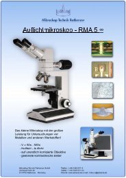
2. Starting Operations<br />
2.1. Assembly<br />
Please open carefully the packaging of the<br />
microscope.<br />
At first the microscope stand (10) has to be<br />
taken out of the packaging and has to be put on<br />
a plan subsoil. After that the incident light tube<br />
(4) has to be set on the quick-change equipment<br />
of the microscope stand. Clamp it with the<br />
screw.<br />
The binocular straight tube (2) and the angled<br />
tube (3) has to be taken from the packaging.<br />
Assemble the binocular straight tube into the<br />
quick-change equipment of the angled tube and<br />
clamp it with a screw.<br />
Take this pre-assembled parts and set them to the<br />
quick-change equipment of the incident light tube<br />
and clamp it with the screw.<br />
Now the objectives will be taken out of their<br />
protective packaging and the objectives has to<br />
be placed into the revolving nosepiece (5) in<br />
this way, that if the revolver will be rotated<br />
clockwise, the magnification will be increase.<br />
The stage (gliding stage, stage carrier with<br />
object guide or stage carrier with rotary table)<br />
will be done into the stage holder (7) and will<br />
be clamped. The adjustment of the objectives<br />
will be done by the combined coaxial coarse<br />
and fine drive adjustment (9).<br />
At last the eyepieces GF – Pw 10x/20 (1) will<br />
be assembled into the binocular straight tube.<br />
The eyepiece can be used with or without<br />
eyecups. The eyepiece is usable as eyepiece for<br />
spectacles. To avoid dirt within the tube, the<br />
eyepieces should be stay the whole time in the<br />
tube.<br />
10<br />
The power connection of the incident light tube<br />
can be found on the backside of the microscope<br />
base (8). The intensity of the incident light<br />
illumination can be set by the adjustment in front<br />
of the microscope base.<br />
Further it is possible to use different filter in the<br />
filter holder of the incident light tube.<br />
2.2. Adjusting the sharpness<br />
The adjustment of the sharpness is only<br />
necessary if the binocular straight tube is in use.<br />
The microscope can be adjusted in that kind that<br />
a sharp image is the result at all levels of<br />
magnifications.<br />
You can achieve this in the following way:<br />
- The distance of the eyepieces has to be<br />
adjusted by screwing up the eyepiece cone to<br />
the individual interpupillary distance.<br />
- The left dioptre ring has to be adjusted to -0- .<br />
- Adjust a sharp picture with help of the drive<br />
mechanism (you have to look with the right eye<br />
through the right eyepiece).<br />
- You have to adjust the sharpness on the left eye<br />
by adjusting the dioptre ring.<br />
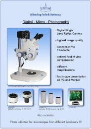
2.3. Incident light illumination<br />
The incident light illumination tube consists a<br />
intermediate tube with a tube factor of 1x or<br />
1,6x, an illuminating adapter and a 3W-LED<br />
illumination.<br />
The objects will be illuminated by a 3W-LED<br />
incident light illumination (Koehler principle).<br />
The aperture diaphragm and the field<br />
diaphragm are integrated in the illuminating<br />
adapter.