CAMP LEJEUNE, NORTH CAROLINA - Senate Judiciary Committee
CAMP LEJEUNE, NORTH CAROLINA - Senate Judiciary Committee
CAMP LEJEUNE, NORTH CAROLINA - Senate Judiciary Committee

You also want an ePaper? Increase the reach of your titles
YUMPU automatically turns print PDFs into web optimized ePapers that Google loves.
AIR SYSTEM TAB PROCEDURES<br />
10) Verify the nclton of all fan conhol dnmpm., shul<br />
down controls, and ahllow safely conlrols.<br />
11) Prepare lha required rep.od forms and .ubmil<br />
as required. (See Seclion VIII raped Iorms).<br />
XHAUST AND RETURN<br />
AIR SYSTEMS<br />
1) Follow paragraphs through 6 for exlmusl air<br />
fans end 1 Ihrough 7 for rolurn air fans under<br />
Sub-Section A--"Baslc Air Syslem Procedures"<br />
In Ihis section for return and exhaust<br />
systems.<br />
2) Delermlne lhe volume of air being moved by<br />
exhaust fan at design rpm by one or more of<br />
following methods. the preferred melhods are:<br />
a) Pilot lube lransverse of Ihe main duct or lhe<br />
ducts leaving the fan discharge.<br />
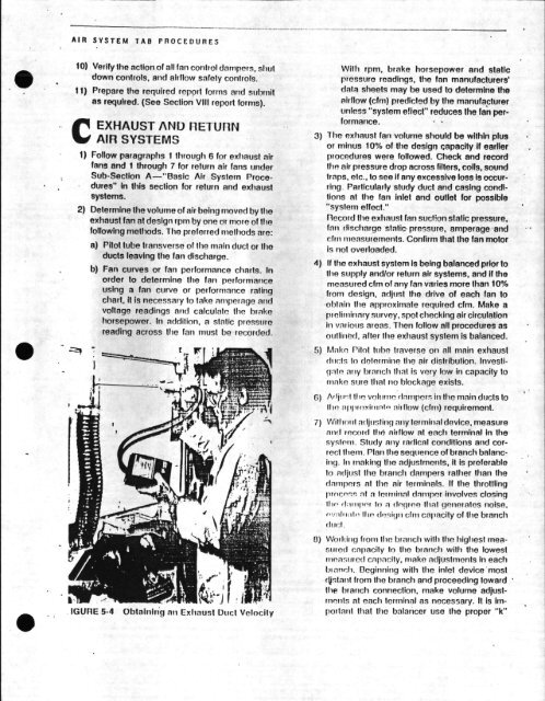
b) Fan curves or fan performance chmls. In<br />
order Io determine Ihe fan performance<br />
using a fan curve or perfornmnce rating<br />
chad, it is necessary !o lake amperage nnd<br />
vollage readings nnd calculaln lhe brake<br />
horsepower. In nddilion, a slnlic pressure<br />
reading across the fan must be recorded.<br />
IGUFIE 5-4 Oblalnlr’g nn Exhausl Ducl Velocily<br />
Wilh rpm, brake horsepower and<br />
pressure readings, lhe fan manufacturers’<br />
dala sheels may be used Io delermlne the<br />
airflow (cfm) predicled by Ihe manufa,clurer<br />
unless "syslem e!iecr’ reduces lhe fan performance.<br />
3) 1ho exhaust fan volume should be wilhin plus<br />
or minus 10% of Ihe design capacily if earlier<br />
procedures were followed. Check and record<br />
lira air pressure drop across fillers, cobs, sound<br />
Imps, etc., to see if nny excessive loss Is occurring.<br />
Parllcularly study duct and casing condllions<br />
nt Ihe fan inlel and outlet for possible<br />
"system effect."<br />
Record the exhnu! fan sgcfion slallc pressure,<br />
fnn discharge static, pressure, amperage ’and<br />
fm nmnuremenls. Confirm Ihal Ihe fan lor<br />
i not overloaded.<br />
4) If the exhaust syslem Is being balanced prior to<br />
Ihe supply and/or relurn air syslems, and if the<br />
measured cfm of nny fan vrles more than t0%<br />
from design, adjust Ihe drive of each fan Io<br />
obtain Ihe approximate required cfm. Make<br />
proliminn ttrvey, spot checking air circulnlion<br />
in vmiou arena. Then follow all procedures<br />
outlimd, nfler the exhausl system is balanced.<br />
5) Mk Pitol tuh Irnverso on nil main exhausl<br />
Htct h) dqtmmin lhe ir disIrihtJlion. Invesliqnln<br />
mW brnnch Ihnl i vn low in capncily to<br />
make ure Ihnt no blockage exists.<br />
fi) AIj’:I llq vohrm lnrpor in Ihe main ducls !o<br />
7)<br />
Wilh, d adjusting any lermial device, measure<br />
syslmn. Study nny rndicnl conditions and correcl<br />
them. Plan the eqtmnce of brnnch bnlancig.<br />
In making the ndjustmenls, it is preferable<br />
to ndjusl Ihe branch dampers rather than the<br />
dnmpms al lira air lerminals. If Ihe lhrollling<br />
I}mCnn nl n Iffrmit}nl dmpnr ivolves closing<br />
O) Woddl hem the brmch with the highesl menmred<br />
cnpacily In Iho brmch wilh lhe Iowesl<br />
mnnued cpncily, make adjuslmenls In each<br />
Ianch. Beginning wilh Ihe inlel devicemosl<br />
nlanl from lhe branch and proceeding Ioward<br />
lhe branch conneclion, make volume adjuslmeals<br />
al each lerminnl as necessa. I1 Is impoHmd<br />
Ihat Ihe balancer use Ihe proper "k"