Bedienungsanleitung, Manuel, Manual, Manuale, 9203, PR ...
Bedienungsanleitung, Manuel, Manual, Manuale, 9203, PR ...
Bedienungsanleitung, Manuel, Manual, Manuale, 9203, PR ...

Create successful ePaper yourself
Turn your PDF publications into a flip-book with our unique Google optimized e-Paper software.
Revision date:<br />
2009-12-10<br />
Version Revision<br />
V3 R0<br />
Prepared by:<br />
PB<br />
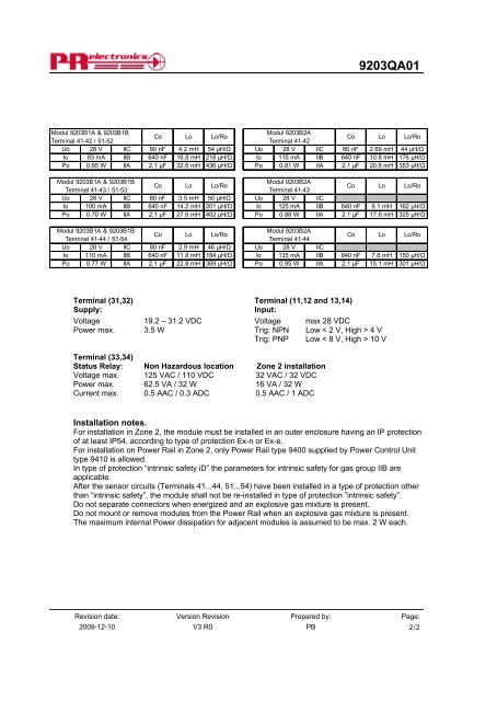
<strong>9203</strong>QA01<br />
Modul <strong>9203</strong>B1A & <strong>9203</strong>B1B<br />
Terminal 41-42 / 51-52<br />
Co Lo Lo/Ro<br />
Modul <strong>9203</strong>B2A<br />
Terminal 41-42<br />
Co Lo Lo/Ro<br />
Uo 28 V IIC 80 nF 4.2 mH 54 μH/Ω Uo 28 V IIC 80 nF 2.69 mH 44 μH/Ω<br />
Io 93 mA IIB 640 nF 16.8 mH 218 μH/Ω Io 115 mA IIB 640 nF 10.8 mH 176 μH/Ω<br />
Po 0.65 W IIA 2.1 μF 32.6 mH 436 μH/Ω Po 0.81 W IIA 2.1 μF 20.8 mH 353 μH/Ω<br />
Modul <strong>9203</strong>B1A & <strong>9203</strong>B1B<br />
Terminal 41-43 / 51-53<br />
Co Lo Lo/Ro<br />
Modul <strong>9203</strong>B2A<br />
Terminal 41-43<br />
Co Lo Lo/Ro<br />
Uo 28 V IIC 80 nF 3.5 mH 50 μH/Ω Uo 28 V IIC<br />
Io 100 mA IIB 640 nF 14.2 mH 201 μH/Ω Io 125 mA IIB 640 nF 9.1 mH 162 μH/Ω<br />
Po 0.70 W IIA 2.1 μF 27.6 mH 402 μH/Ω Po 0.88 W IIA 2.1 μF 17.6 mH 325 μH/Ω<br />
Modul <strong>9203</strong>B1A & <strong>9203</strong>B1B<br />
Terminal 41-44 / 51-54<br />
Co Lo Lo/Ro<br />
Modul <strong>9203</strong>B2A<br />
Terminal 41-44<br />
Co Lo Lo/Ro<br />
Uo 28 V IIC 80 nF 2.9 mH 46 μH/Ω Uo 28 V IIC<br />
Io 110 mA IIB 640 nF 11.8 mH 184 μH/Ω Io 135 mA IIB 640 nF 7.8 mH 150 μH/Ω<br />
Po 0.77 W IIA 2.1 μF 22.8 mH 369 μH/Ω Po 0.95 W IIA 2.1 μF 15.1 mH 301 μH/Ω<br />
Terminal (31,32) Terminal (11,12 and 13,14)<br />
Supply: Input:<br />
Voltage 19.2 – 31.2 VDC Voltage max 28 VDC<br />
Power max. 3.5 W Trig: NPN Low < 2 V, High > 4 V<br />
Trig: PNP Low < 8 V, High > 10 V<br />
Terminal (33,34)<br />
Status Relay: Non Hazardous location Zone 2 installation<br />
Voltage max. 125 VAC / 110 VDC 32 VAC / 32 VDC<br />
Power max. 62.5 VA / 32 W 16 VA / 32 W<br />
Current max. 0.5 AAC / 0.3 ADC 0.5 AAC / 1 ADC<br />
Installation notes.<br />
For installation in Zone 2, the module must be installed in an outer enclosure having an IP protection<br />
of at least IP54, according to type of protection Ex-n or Ex-e.<br />
For installation on Power Rail in Zone 2, only Power Rail type 9400 supplied by Power Control Unit<br />
type 9410 is allowed.<br />
In type of protection “intrinsic safety iD” the parameters for intrinsic safety for gas group IIB are<br />
applicable.<br />
After the sensor circuits (Terminals 41...44, 51...54) have been installed in a type of protection other<br />
than “intrinsic safety”, the module shall not be re-installed in type of protection ”intrinsic safety”.<br />
Do not separate connectors when energized and an explosive gas mixture is present.<br />
Do not mount or remove modules from the Power Rail when an explosive gas mixture is present.<br />
The maximum internal Power dissipation for adjacent modules is assumed to be max. 2 W each.<br />
Page:<br />
2/2
![Bedienungsanleitung Typ BA_8627_8628_8632_DE [PDF, 459 KB]](https://img.yumpu.com/23348412/1/184x260/bedienungsanleitung-typ-ba-8627-8628-8632-de-pdf-459-kb.jpg?quality=85)
![Bedienungsanleitung_Typ BA_optris CT LT_DE [PDF, 4.00 MB]](https://img.yumpu.com/22293726/1/190x133/bedienungsanleitung-typ-ba-optris-ct-lt-de-pdf-400-mb.jpg?quality=85)
![Komplettes Datenblatt Typ 8821_DE [PDF, 499 KB] - MTS ...](https://img.yumpu.com/21876808/1/184x260/komplettes-datenblatt-typ-8821-de-pdf-499-kb-mts-.jpg?quality=85)
![Komplettes Datenblatt Typ 1440_DE [PDF, 524 KB] - MTS ...](https://img.yumpu.com/21876799/1/184x260/komplettes-datenblatt-typ-1440-de-pdf-524-kb-mts-.jpg?quality=85)

![Komplettes Datenblatt Typ 8411_DE [PDF, 459 KB] - MTS ...](https://img.yumpu.com/20642872/1/184x260/komplettes-datenblatt-typ-8411-de-pdf-459-kb-mts-.jpg?quality=85)

![Manual CT13 Serie [PDF, 1.00 MB] - MTS Messtechnik ...](https://img.yumpu.com/20620646/1/184x260/manual-ct13-serie-pdf-100-mb-mts-messtechnik-.jpg?quality=85)
![Komplettes Datenblatt Typ 4503A_DE [PDF, 795 KB] - MTS ...](https://img.yumpu.com/20620634/1/184x260/komplettes-datenblatt-typ-4503a-de-pdf-795-kb-mts-.jpg?quality=85)


![Prüfstandssysteme [PDF, 2.00 MB] - MTS Messtechnik Schaffhausen ...](https://img.yumpu.com/18883102/1/184x260/prufstandssysteme-pdf-200-mb-mts-messtechnik-schaffhausen-.jpg?quality=85)