erbauer 254mm (10?) single bevel sliding mitre saw
erbauer 254mm (10?) single bevel sliding mitre saw
erbauer 254mm (10?) single bevel sliding mitre saw

You also want an ePaper? Increase the reach of your titles
YUMPU automatically turns print PDFs into web optimized ePapers that Google loves.
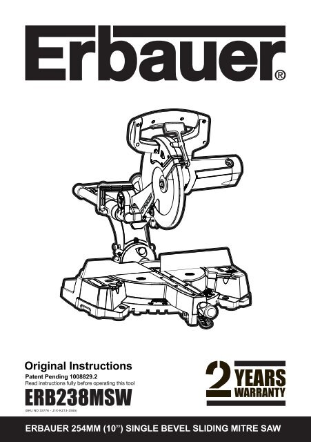
Original Instructions<br />
Patent Pending <strong>10</strong>08829.2<br />
Read instructions fully before operating this tool<br />
ERB238MSW<br />
(SKU NO 33776 - J1X-KZ13-2555)<br />
ERBAUER 254MM (<strong>10</strong>”) SINGLE BEVEL SLIDING MITRE SAW
ERBAUER 254MM (<strong>10</strong>”) SINGLE BEVEL SLIDING MITRE SAW
Congratulations on your purchase of a quality power tool from Erbauer Ltd.<br />
This product should give you reliable service for your peace of mind this power<br />
tool does carry a 24-month guarantee, the terms of which are detailed below.<br />
If this product develops a fault within the guarantee period contact your retailer.<br />
Please retain this handbook in case you need to refer to safety, care or guarantee<br />
information in the future.<br />
GUARANTEE<br />
This product carries an Erbauer Ltd guarantee of 24 months. If your<br />
<br />
<br />
for a full refund or we will repair or replace the goods if you prefer. When repair<br />
is not practical or identical goods are not available, alternative goods of similar<br />
<br />
a partial or full refund depending on the time period since purchase.<br />
<br />
-Fair wear and tear<br />
-Misuse or abuse<br />
-Lack of routine maintenance<br />
-Failure of consumable items (such as batteries)<br />
-Accidental damage<br />
-Cosmetic damage<br />
-Failure to follow manufacturer’s guidelines<br />
-Loss of use of the goods<br />
-Repairs attempted by anyone, unless authorised by Erbauer Ltd.<br />
This guarantee does not affect your statutory rights. This guarantee is only valid in the<br />
UK.<br />
For further technical advice and spare parts, please contact your retailer <br />
your Erbauer model number.<br />
ERBAUER 254MM (<strong>10</strong>”) SINGLE BEVEL SLIDING MITRE SAW
SAFETY INSTRUCTIONS<br />
WARNING! When using electric tools basic safety precautions should always<br />
<br />
including the following.<br />
Read all these instructions before attempting to operate this product and save these<br />
instructions.<br />
SAVE THESE INSTRUCTIONS<br />
The term “power tool” in the warning refers to your mains-operated (corded) power<br />
tool or battery-operated (cordless) power tool.<br />
1 Keep work area clear<br />
<br />
2 Consider work area environment<br />
<br />
- Do not use tools in damp or wet locations.<br />
- Keep work area well lit.<br />
<br />
3 Guard against electric shock<br />
- Avoid body contact with earthed or grounded surfaces (e.g. pipes, radiators,<br />
ranges, refrigerators).<br />
4 Keep other persons away<br />
- Do not let persons, especially children, not involved in the work touch the tool or<br />
<br />
5 Store idle tools<br />
- When not in use, tools should be stored in a dry locked-up place, out of reach of<br />
children.<br />
6 Do not force the tool<br />
<br />
7 Use the right tool<br />
<br />
<br />
to cut tree limbs or logs.<br />
8 Dress properly<br />
<br />
- Non-skid footwear is recommended when working outdoors.<br />
- Wear protective hair covering to contain long hair.<br />
9 Use protective equipment<br />
- Use safety glasses.<br />
- Use face or dust mask if working operations create dust.<br />
<strong>10</strong> Connect dust extraction equipment<br />
<br />
<br />
11 Do not abuse the cord<br />
- Never yank the cord to disconnect it from the socket. Keep the cord away from<br />
heat, oil and sharp edges.<br />
ERBAUER 254MM (<strong>10</strong>”) SINGLE BEVEL SLIDING MITRE SAW
12 Secure work<br />
- Where possible use clamps or a vice to hold the work. It is safer than using your hand.<br />
13 Do not overreach<br />
- Keep proper footing and balance at all times.<br />
14 Maintain tools with care<br />
- Keep cutting tools sharp and clean for better and safer performance.<br />
- Follow instruction for lubricating and changing accessories.<br />
- Inspect tool cords periodically and if damaged have them repaired by an<br />
authorized service facility.<br />
<br />
- Keep handles dry, clean and free from oil and grease.<br />
15 Disconnect tools<br />
- When not in use, before servicing and when changing accessories such as blades,<br />
bits and cutters, disconnect tools from the power supply.<br />
16 Remove adjusting keys and wrenches<br />
<br />
from the tool before turning it on.<br />
17 Avoid unintentional starting<br />
- Ensure switch is in “off” position when plugging in.<br />
18 Use outdoor extension leads<br />
<br />
and so marked.<br />
19 Stay alert<br />
- Watch what you are doing, use common sense and do not operate the tool when<br />
you are tired.<br />
20 Check damaged parts<br />
- Before further use of tool, it should be carefully checked to determine that it will<br />
operate properly and perform its intended function.<br />
- Check for alignment of moving parts, binding of moving parts, breakage of parts,<br />
mounting and any other conditions that may affect its operation.<br />
- A guard or other part that is damaged should be properly repaired or replaced by<br />
an authorised service centre unless otherwise indicated in this instruction manual.<br />
- Have defective switches replaced by an authorised service centre.<br />
- Do not use the tool if the switch does not turn it on and off.<br />
21 Warning<br />
- The use of any accessory or attachment other than one recommended in this<br />
<br />
<br />
- This electric tool complies with the relevant safety rules. Repairs should only be<br />
<br />
in considerable danger to the user.<br />
ERBAUER 254MM (<strong>10</strong>”) SINGLE BEVEL SLIDING MITRE SAW
HEALTH ADVICE<br />
Warning! When drilling, sanding, <strong>saw</strong>ing or grinding, dust particles will be<br />
produced. In some instances, depending on the materials you are working<br />
with, this dust can be particularly harmful to you (e.g. lead from old gloss paint).You<br />
are advised to consider the risks associated with the materials you are working with<br />
<br />
-Work in a well-ventilated area.<br />
<br />
<br />
SAFETY INSTRUCTIONS FOR ALL SAWS<br />
a. DANGER: Keep hands away from cutting area and the blade. Keep your second<br />
hand on the handle, or motor housing. If both hands are holding the <strong>saw</strong>, they<br />
cannot be cut by the blade.<br />
b. Do not reach underneath the workpiece. The guard cannot protect you from the<br />
blade below the workpiece.<br />
c. Adjust the cutting depth to the thickness of the workpiece. Less than a full tooth<br />
of the blade teeth should be visible below the workpiece.<br />
d. Never hold piece being cut in your hands or across your leg. Secure the<br />
workpiece to a stable platform. It is important to support the work properly to<br />
<br />
e. Hold power tool by insulated gripping surfaces when performing an operation<br />
where the cutting tool may contact hidden wiring or its own cord. Contact with a<br />
<br />
operator.<br />
f. When ripping always use a rip fence or straight edge guide. This improves the<br />
accuracy of cut and reduces the chance of blade binding.<br />
g. Always use blades with correct size and shape (diamond versus round) of<br />
arbor holes. Blades that do not match the mounting hardware of the <strong>saw</strong> will run<br />
eccentrically, causing loss of control.<br />
h. Never use damaged or incorrect blade washers or bolt. The blade washers and<br />
bolt were specially designed for your <strong>saw</strong>, for optimum performance and safety of<br />
operation.<br />
Further safety instructions for all <strong>saw</strong>s<br />
<br />
<br />
an uncontrolled <strong>saw</strong> to lift up and out of the workpiece toward the operator;<br />
<br />
and the motor reaction drives the unit rapidly back toward the operator;<br />
<br />
the blade can dig into the top surface of the wood causing the blade to climb out of<br />
<br />
Kickback is the result of <strong>saw</strong> misuse and/or incorrect operating procedures or<br />
conditions and can be avoided by taking proper precautions as given below.<br />
ERBAUER 254MM (<strong>10</strong>”) SINGLE BEVEL SLIDING MITRE SAW
kickback forces. Position your body to either side of the blade, but not in line with<br />
the blade. <br />
be controlled by the operator, if proper precautions are taken.<br />
b. When blade is binding, or when interrupting a cut for any reason, release the<br />
trigger and hold the <strong>saw</strong> motionless in the material until the blade comes to a<br />
complete stop. Never attempt to remove the <strong>saw</strong> from the work or pull the <strong>saw</strong><br />
backward while the blade is in motion or kickback may occur. Investigate and take<br />
corrective actions to eliminate the cause of blade binding.<br />
c. When restarting a <strong>saw</strong> in the workpiece, centre the <strong>saw</strong> blade in the kerf and<br />
check that <strong>saw</strong> teeth are not engaged into the material. If <strong>saw</strong> blade is binding, it<br />
may walk up or kickback from the workpiece as the <strong>saw</strong> is restarted.<br />
d. Support large panels to minimise the risk of blade pinching and kickback. Large<br />
panels tend to sag under their own weight. Supports must be placed under the panel<br />
on both sides, near the line of cut and near the edge of the panel.<br />
e. Do not use dull or damaged blades. Unsharpened or improperly set blades<br />
<br />
f. Blade depth and <strong>bevel</strong> adjusting locking levers must be tight and secure before<br />
making cut. <br />
kickback.<br />
ERBAUER 254MM (<strong>10</strong>”) SINGLE BEVEL SLIDING MITRE SAW
ADDITIONAL SAFETY INSTRUCTIONS FOR YOUR MITRE SAW<br />
Warning: Be sure to read and understand all instructions. Failure to<br />
<br />
or serious personal injury.<br />
1. Know your power tool. Read operator’s manual carefully. Learn the applications<br />
<br />
2. Always wear safety glasses or eye shields when using this <strong>mitre</strong> <strong>saw</strong>. Everyday<br />
eyeglasses have only impact-resistant lenses; they are not safety glasses.<br />
3. Always protect your lungs. Wear a face mask or dust mask if the operation is dusty.<br />
Always use dust extraction equipment to minimise dust.<br />
4. Always protect your hearing. Wear hearing protection during extended periods<br />
of operation.<br />
5. Always inspect the tool cords periodically and if damaged have them repaired.<br />
Always be aware of the cord location.<br />
6. Always check for damaged parts. Before further use of the tool, a guard or<br />
other part that is damaged should be carefully checked to determine if it will<br />
operate properly and perform its intended function. Check for misalignment or<br />
binding of moving parts, breakage of parts, and any other condition that may<br />
affect the tool’s operation. A guard or other part that is damaged should be<br />
<br />
7. Do not abuse the cord. Never use the cord to carry the tools or pull the plug from<br />
the socket. Keep cord away from heat, oil, sharp edges or moving parts. Replace<br />
damaged cords immediately. Damaged cords increase the risk of electric shock.<br />
8. Always make sure that your extension cord is in good condition. When using<br />
an extension cord be sure to use one that is heavy enough to carry the current<br />
that your tool will draw. An undersized cord will cause a drop in line voltage,<br />
resulting in loss of power and overheating.<br />
9. Always inspect and remove all nails from lumber before <strong>saw</strong>ing.<br />
<br />
medication<br />
<br />
11. Save these instructions. Refer to them frequently and use them to instruct<br />
others who may use this tool. If someone borrows this tool, make sure they have<br />
these instructions also.<br />
<br />
recommended for cutting wood and plastic only.<br />
13. Do not use <strong>saw</strong> blades with High Speed Steel (HSS) or damaged or deformed<br />
blades.<br />
14. Replace the table insert when worn.<br />
15. Use only <strong>saw</strong> blades recommended by the manufacturer and which have the<br />
exact bore and diameter required for this machine.<br />
16. Connect your <strong>mitre</strong> <strong>saw</strong> to a dust collecting device (I. D.Ø32mm) when <strong>saw</strong>ing.<br />
17. Select <strong>saw</strong> blades in relation to the material to be cut.<br />
18. Check the maximum depth of cut.<br />
19. When <strong>saw</strong>ing long work pieces, always use extra support to provide better<br />
support, and use clamps or other clamping devices.<br />
ERBAUER 254MM (<strong>10</strong>”) SINGLE BEVEL SLIDING MITRE SAW
20. The operator is adequately trained in the use, adjustment and operation and<br />
operation of the machine.<br />
21. Provide for adequate room lighting at your workplace or for adequate lighting<br />
of the immediate work area.<br />
<br />
Repairs shall only be carried out by the laser manufacturer or an authorised<br />
agent.<br />
23. Refrain from removing any cut-offs or other parts of the workpiece from<br />
the cutting area whilst the machine is running and the <strong>saw</strong> head is not the rest<br />
position.<br />
24. Never stand on this tool. Serious injuries could occur when this tool tips over<br />
or when coming in contact with the <strong>saw</strong> blade.<br />
25. Only use the <strong>saw</strong> with guards in good working order and properly maintained,<br />
and in position.<br />
<br />
27. Ensure the speed marked on the <strong>saw</strong> blade is at least equal to the speed<br />
marked on the <strong>saw</strong>.<br />
28. Warning. Not replace the laser with a different type. Instruction that repairs<br />
shall only be carried out by the laser manufacturer or an authorised agent.<br />
WARNING:<br />
thrown into your eyes, which can result in severe eye damage. Before<br />
beginning power tool operation, always wear safety goggles or safety glasses with<br />
side shield and a full face shield when needed.<br />
WARNING: If any parts are missing, do not operate your <strong>mitre</strong> <strong>saw</strong> until the<br />
missing parts are replaced. Failure to follow this rule could result in serious<br />
<br />
Caution: Do not let familiarity with your <strong>mitre</strong> <strong>saw</strong> make you careless. Remember<br />
<br />
Double insulation:<br />
<br />
electrically insulated from the mains power supply. This is done by placing insulation<br />
barriers between the electrical and mechanical components making it unnecessary<br />
for the tool to be earthed.<br />
Important note<br />
Be sure the supply is the same as the voltage given on the rating plate. The tool is<br />
<br />
<br />
SAFETY RULES FOR LASER LIGHT<br />
<br />
wavelength.<br />
These lasers do not normally present an optical hazard, although staring at the<br />
<br />
WARNING:<br />
<br />
ERBAUER 254MM (<strong>10</strong>”) SINGLE BEVEL SLIDING MITRE SAW
- The laser shall be used and maintained in accordance with the manufacturer’s<br />
instructions.<br />
<br />
- The laser beam shall not be deliberately aimed at personnel and shall be prevented<br />
<br />
<br />
<br />
<br />
direct the beam back at the operator.<br />
- Do not change the laser light assembly with a different type. Repairs must be<br />
carried out by the laser manufacturer or an authorised agent.<br />
SPECIFIC SAFETY RULES & SYMBOLS<br />
WARNING!<br />
Do not operate machine if warning and / or instruction labels are missing or damaged.<br />
Symbol Description<br />
V Volts<br />
A Amperes<br />
Hz Hertz<br />
Min-1 Speed<br />
~ Alternating Current<br />
no No Load Speed<br />
Double Insulated<br />
Wear Safety Goggles<br />
Wear Ear Protection<br />
Wear Dust Mask<br />
Read Instruction Manual<br />
Laser Warning Symbol<br />
Conforms to relevant<br />
safety standards<br />
General Warning<br />
ERBAUER 254MM (<strong>10</strong>”) SINGLE BEVEL SLIDING MITRE SAW
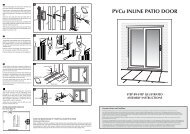
KNOW YOUR SLIDING MITRE SAW<br />
Fig 1<br />
14<br />
1. DUST BAG<br />
2. UPPER BLADE GUARD<br />
3. CUTTING HANDLE<br />
4. LOWER BLADE GUARD<br />
5. BLADE<br />
6. TABLE INSERT<br />
7. MITRE HANDLE<br />
8. LASER GUIDE<br />
9. BASE<br />
<strong>10</strong>. TURNTABLE<br />
11. LEFT EXTENSION TABLE<br />
12. FENCE<br />
13. HOLD-DOWN CLAMP<br />
14. SLIDE CARRIAGE LOCK KNOB<br />
8<br />
11<br />
1<br />
9<br />
2<br />
<strong>10</strong><br />
ERBAUER 254MM (<strong>10</strong>”) SINGLE BEVEL SLIDING MITRE SAW<br />
5<br />
6<br />
4<br />
3<br />
12<br />
7<br />
13
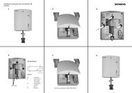
Fig 2<br />
20<br />
21<br />
15. CARRYING HANDLE<br />
16. SLIDE CARRIAGE<br />
17. BEVEL LOCK HANDLE<br />
18. RIGHT EXTENSION TABLE<br />
19. MOTOR<br />
20. POSITIVE STOP LOCKING LEVER<br />
21. LOWER BLADE GUARD LOCK LEVER<br />
<br />
23. ADJUSTABLE CUTTING STOP<br />
ERBAUER 254MM (<strong>10</strong>”) SINGLE BEVEL SLIDING MITRE SAW<br />
19<br />
22<br />
18<br />
16<br />
15<br />
17<br />
23
TECHNICAL DATA<br />
<br />
<br />
-1<br />
II<br />
<br />
<br />
<br />
<br />
<br />
<br />
<br />
<br />
<br />
<br />
<br />
NOISE AND VIBRATION DATA<br />
<br />
<br />
22 )<br />
- The declared vibration total value has been measured in accordance with a<br />
standard test method and may be used for comparing one tool with another.<br />
- The declared vibration total value may also be used in a preliminary assessment of<br />
<br />
WARNING: The vibration emission during actual use of the power tool can differ<br />
from the declared total value depending on the ways in which the tool is used; and<br />
of the need to identify safety measures to protect the operator that are based on an<br />
<br />
the operating cycle such as the times when the tool is switched off and when it is<br />
running idle in addition to the trigger time).<br />
ACCESSORIES<br />
Allen Key 1 pc<br />
Dust Bag 1 pc<br />
Hold-Down Clamp 1 pc<br />
Mitre Handle 1 pc<br />
ERBAUER 254MM (<strong>10</strong>”) SINGLE BEVEL SLIDING MITRE SAW
VIBRATION<br />
The European Physical Agents (Vibration) Directive has been brought in to help<br />
<br />
<br />
results to enable users to make informed decisions as to the period of time a power<br />
tool can be used safely on a daily basis and the choice of tool.Further Advice can be<br />
found at www.hse.gov.uk<br />
<br />
<br />
Test prodcure GS mark.<br />
<br />
<br />
The declared vibration emission value should be used as a minimum level should be used with<br />
the current guidance on vibration.<br />
<br />
has further information.<br />
The declared vibration emission been measured in accordance with a standardised test stated<br />
above and may be used to compare one tool with another.<br />
<br />
Warning: The vibration emission value during actual use of the power tool can differ<br />
from the declared value depending on the ways in which the tool is used<br />
<br />
How the tool is used and the materials being cut or drilled.<br />
The tool being in good condition and well maintained<br />
The use the correct accessory for the tool and ensuring it is sharp and in good condition.<br />
And the tool is being used as intended by its design and these instructions.<br />
This tool may cause hand-arm vibration syndrome<br />
if its use is not adequately managed<br />
Warning: identify safety measures to protect the operator that are based on an<br />
<br />
of the operating cycle such as the times when the tool is switched off and when it is<br />
running idle in addition to the trigger time).Note The use of other tools will reduce the<br />
<br />
ALWAYS use sharp chisels, drills and blades. Maintain this tool in accordance with these instructions<br />
and keep well lubricated (where appropriate)<br />
<br />
Plan your work schedule to spread any high vibration tool use across a number of days.<br />
Health Surveillance<br />
All employees should be part of an employer’s health surveillance scheme to help identity<br />
any vibration related diseases at an early stage, prevent disease progression and<br />
help employees stay in work.<br />
ERBAUER 254MM (<strong>10</strong>”) SINGLE BEVEL SLIDING MITRE SAW
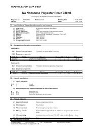
Fig 3<br />
Fig 4<br />
Fig 5<br />
2<br />
1<br />
1<br />
3<br />
1<br />
ASSEMBLY INSTRUCTIONS<br />
Warning:<br />
this <strong>mitre</strong> <strong>saw</strong> to the power source until<br />
<br />
have read and understood this Operator’s Manual.<br />
1. Installing the <strong>mitre</strong> handle<br />
1) Thread the <strong>mitre</strong> handle (1) into the hole<br />
<br />
2. Unlocking the slide carriage<br />
After removing the <strong>saw</strong> from the carton,<br />
loosen the slide carriage lock knob (1). When<br />
transporting or storing the <strong>mitre</strong> <strong>saw</strong>, the slide<br />
carriage should always be locked in position.<br />
The slide carriage lock knob (1) is located on the<br />
<br />
3. Raising the Cutting Head<br />
1) Push down slightly on the switch handle (1)<br />
and the lock lever (2).<br />
2) Pull out the stop latch knob (3).<br />
3) Allow the cutting head to rise to the up<br />
<br />
Warning:<br />
to the <strong>saw</strong>, transport and store the<br />
<strong>mitre</strong> <strong>saw</strong> with the cutting head locked in the<br />
down position. Never use the stop latch to hold<br />
the cutting head in a down position for cutting<br />
operations.<br />
Locking<br />
When transporting or storing the <strong>mitre</strong> <strong>saw</strong>, the<br />
cutting head should always be locked in the down<br />
position.<br />
1) Push the lock lever (2) and cutting head down<br />
to its lowest position.<br />
2) Push the stop latch knob (3) into the locking<br />
hole.<br />
IMPORTANT<br />
To avoid damage, never carry the <strong>mitre</strong> <strong>saw</strong> by<br />
the cutting arm or the <strong>mitre</strong> handle. ALWAYS use<br />
both designated carrying handles together.<br />
ERBAUER 254MM (<strong>10</strong>”) SINGLE BEVEL SLIDING MITRE SAW
4. Installing the dust bag<br />
<br />
dust bag (1).<br />
2) Place the dust bag neck opening around the<br />
<br />
<br />
5. Installing the hold-down clamp<br />
1) Loosen the lock knob (1) from the rear side<br />
<br />
2) Place the hold-down clamp assembly (3) in<br />
<br />
<br />
Warning: When using stop block on<br />
the right side, hold-down clamp must<br />
also be in right side. Using hold-down clamp<br />
on the left side during this operation can cause<br />
<br />
Fig 6<br />
Fig 7<br />
<br />
ERBAUER 254MM (<strong>10</strong>”) SINGLE BEVEL SLIDING MITRE SAW<br />
1<br />
4 4<br />
2<br />
3<br />
3<br />
1<br />
2
5<br />
<br />
2) Spring washer<br />
3) Flat washer<br />
4) Mitre <strong>saw</strong> base<br />
5) Workbench<br />
6) Flat washer<br />
7) Spring washer<br />
<br />
<br />
4<br />
6<br />
7<br />
3<br />
1<br />
2<br />
8<br />
9<br />
6. Mounting the <strong>mitre</strong> <strong>saw</strong><br />
Warning:<br />
<br />
<br />
and lock the cutting head in the lower position<br />
using the stop latch.<br />
<br />
the slide carriage lock knob.<br />
<br />
designated carrying handles located on the<br />
top of the machine. When lifting, bend at your<br />
knees, not from your back.<br />
<br />
or by the switch handle. Carrying the tool by<br />
the power cord could cause damage to the<br />
insulation or the wire connections resulting in<br />
<br />
<br />
visitors to stand near the <strong>saw</strong> during any cutting<br />
operation.<br />
<br />
<br />
Mounting instructions<br />
1) For stationary use, place the <strong>saw</strong> in the desired<br />
location, directly on a workbench where there<br />
is room for handling and proper support of the<br />
workpiece. The base of the <strong>saw</strong> has four mounting<br />
holes. Bolt the base of the <strong>mitre</strong> <strong>saw</strong> (1) to the<br />
work surface (5),using the fastening method as<br />
<br />
2) For portable use, place the <strong>saw</strong> on a<br />
<br />
base of the <strong>mitre</strong> <strong>saw</strong> securely to the plywood<br />
using the mounting holes on the base. Use<br />
G-clamps to clamp this mounting board to a stable<br />
<br />
Note: Mounting hardware is not included with this<br />
tool. Bolts, nuts, washers and screws must be<br />
purchased separately.<br />
ERBAUER 254MM (<strong>10</strong>”) SINGLE BEVEL SLIDING MITRE SAW
7. Removing and installing the blade<br />
Warning:<br />
<br />
diameter.<br />
<br />
sure the switch is in the OFF position and the<br />
plug is not connected to the power source<br />
socket.<br />
<br />
<br />
operator considers wearing protective gloves<br />
when handling or installing the blade.<br />
Removing blade<br />
1) Unplug the <strong>saw</strong> from the socket.<br />
2) The slide carriage should be locked in<br />
position by tightening the slide carriage lock<br />
<br />
3) Allow the cutting head to rise to the upright<br />
<br />
4) Release the lower blade guard by operating<br />
the blade guard handle, and rotate the guard<br />
into its upper position.<br />
<br />
6) Hold the guard in position with your thumb<br />
<br />
<br />
sized allen key inserted into the arbor bolt (See<br />
until positive location is felt.<br />
<br />
undo the arbor bolt with the allen key by<br />
turning it in a clockwise direction.<br />
<br />
machine.<br />
<br />
gently ease the blade from the spindle and<br />
remove downwards and away from the cutting<br />
head.<br />
Note: Pay attention to the pieces removed,<br />
noting their position and direction they face.<br />
Wipe the blade collars clean of any <strong>saw</strong>dust<br />
before installing a new blade.<br />
Fig 11<br />
Fig 12<br />
Fig 13<br />
Fig 14<br />
ERBAUER 254MM (<strong>10</strong>”) SINGLE BEVEL SLIDING MITRE SAW<br />
1<br />
1
Fig 15<br />
8. Installing Blade<br />
Unplug the <strong>mitre</strong> <strong>saw</strong> before changing/installing<br />
the blade.<br />
Note:<br />
the correct size for this machine and the<br />
<br />
1) Rotate and hold lower blade guard in its<br />
upper position as already described.<br />
<br />
making sure the rotation arrow on the blade<br />
matches the clockwise rotation arrow on the upper<br />
guard and the blade teeth are pointing downward.<br />
3) Place the outer blade collar against the blade<br />
and on the arbor. Thread the arbor bolt onto the<br />
<br />
IMPORTANT<br />
<br />
<br />
4) Place the allen key into the arbor bolt.<br />
5) Press the arbor lock, holding gently while<br />
turning the blade counterclockwise. When arbor<br />
<br />
<br />
Note: Do not press arbor lock when blade is<br />
moving.<br />
Warning: Be sure that the arbor lock<br />
is released so that the blade turns<br />
freely. Lower the blade into the lower table and<br />
check for any contact with the base or the <strong>mitre</strong><br />
table by spinning the blade manually. Make sure<br />
the collars are clean and properly arranged.<br />
Check that the lower blade guard is functioning<br />
correctly and does not bind or stick.<br />
ERBAUER 254MM (<strong>10</strong>”) SINGLE BEVEL SLIDING MITRE SAW
9. Aligning the laser beam<br />
Warning: For your own safety, never<br />
connect the plug to power source<br />
<br />
complete and you have read and understood<br />
the safety and operational instructions. The<br />
laser beam must always be correctly aligned<br />
with the blade to ensure straight, even cutting.<br />
<br />
cutting guide using a Class II laser beam.<br />
The laser beam will enable the operator to<br />
preview the <strong>saw</strong> blade path on the stock to be<br />
cut before starting the <strong>saw</strong>. This laser guide<br />
is powered by the transformed alternating<br />
current supply directly through the power<br />
lead. The <strong>saw</strong> must be connected to the<br />
power source and the laser on/off switch must<br />
be turned on for the laser line to show.<br />
<br />
Warning:<br />
AVOID DIRECT EYE CONTACT<br />
Laser radiated when laser guide is turned on.<br />
Avoid direct eye contact. Always unplug the<br />
<strong>mitre</strong> <strong>saw</strong> from power source before making<br />
<br />
<br />
<br />
<br />
beam Class 2 Laser Product Puissance.<br />
Note:<br />
of this machine have been completed at the<br />
factory. Due to normal wear and use, some<br />
<br />
A. Check Laser Beam Alignment<br />
<br />
to serve as a “pattern line” to test laser<br />
alignment. Lay the board on the <strong>mitre</strong> table.<br />
2) Plug <strong>saw</strong> into socket and turn on the laser<br />
beam and line it up with the pattern line.<br />
3) Lower <strong>saw</strong> blade to pattern line and<br />
<br />
<br />
Fig 16<br />
Laser ON/OFF Switch<br />
ERBAUER 254MM (<strong>10</strong>”) SINGLE BEVEL SLIDING MITRE SAW
Fig 17<br />
<br />
2<br />
1<br />
3<br />
<br />
are provided. Two (1,2) are positioned on the LH<br />
side of the laser housing, and one (3) on the RH<br />
side of the laser housing. These screws gently<br />
hold the laser module in place and on alignment<br />
by bearing on the laser modules casing. It is<br />
<br />
on the laser module casing is maintained as<br />
closely as possible to the factory setting. Do not<br />
over tighten any one screw – damage to the laser<br />
<br />
B Adjusting the Angle of the Laser Guide<br />
1) Loosen the <strong>single</strong> screw on the RH side of<br />
the laser housing ½ a turn.<br />
2)Turn the laser element in the desired direction<br />
<br />
<br />
C Aligning the Laser Beam<br />
<br />
of the laser housing.<br />
<br />
achieved.<br />
Warning: Use only the correct sized<br />
<br />
screws. Turn one screw at a time and only ¼<br />
turn in either direction before checking laser<br />
alignment. Maintain as far as possible the<br />
original factory pressure setting that these<br />
<br />
ERBAUER 254MM (<strong>10</strong>”) SINGLE BEVEL SLIDING MITRE SAW
ADJUSTMENT INSTRUCTIONS<br />
1. Bevel stop adjustment<br />
Warning: <br />
accidental start, make sure the switch is<br />
in the OFF position and the plug is not connected<br />
to the power source socket.<br />
2. 90° (0°) Bevel adjustment<br />
1) Loosen <strong>bevel</strong> lock handle (1) and rotate the<br />
cutting arm completely to the right until it stops<br />
against the vertical stop. Tighten the <strong>bevel</strong> lock<br />
handle.<br />
<br />
table with the ruler against the table and the<br />
<br />
°°<br />
table (5), loosen the <strong>bevel</strong> lock handle (1), tilt the<br />
cutting head to the left, loosen the locknut (4) on the<br />
<br />
<br />
out to increase or decrease the <strong>bevel</strong> angle.<br />
°<br />
°) <strong>bevel</strong> and recheck for alignment.<br />
<br />
is needed.<br />
6) Tighten <strong>bevel</strong> lock handle (1) and locknut (4)<br />
when alignment is achieved. <br />
<br />
1<br />
4<br />
3<br />
2<br />
5<br />
ERBAUER 254MM (<strong>10</strong>”) SINGLE BEVEL SLIDING MITRE SAW
3<br />
Fig 21<br />
Fig 22<br />
1<br />
2<br />
2<br />
3<br />
1<br />
1<br />
2<br />
3<br />
2<br />
4<br />
3<br />
3. Bevel pointer adjustment<br />
°°) to the<br />
table, loosen the <strong>bevel</strong> indicator screw (1) using<br />
a # 2 Phillips screwdriver.<br />
°” mark on<br />
the <strong>bevel</strong> scale and retighten the screw. (See<br />
<br />
4. Bevel adjustment 45°<br />
1) Loosen the <strong>bevel</strong> lock handle (1) and tilt the<br />
cutting head completely to the left.<br />
<br />
the blade angle is 45° to the table.<br />
3) If the blade is not at 45° to the <strong>mitre</strong> table,<br />
tilt the cutting arm to the right, loosen the<br />
<br />
<br />
(3) depth in or out to increase or decrease the<br />
<strong>bevel</strong> angle.<br />
4) Tilt the cutting arm to the left to 45° <strong>bevel</strong><br />
and recheck for alignment.<br />
5) Repeat steps 1 through 4 until the blade is at<br />
<br />
6) Tighten <strong>bevel</strong> lock handle (1) and locknut (2)<br />
when alignment is achieved. <br />
5. Bevel Setting for Crown Moulding<br />
° for<br />
cutting crown mouldings.<br />
1) Twist and deploy sprung-loaded crown<br />
moulding pin (2).<br />
2) Loosen the <strong>bevel</strong> lock handle (1) and rotate<br />
<br />
<br />
<br />
ERBAUER 254MM (<strong>10</strong>”) SINGLE BEVEL SLIDING MITRE SAW
6. Bevel adjustment 33.9 o<br />
° settings can be checked<br />
<br />
<br />
°<br />
<br />
the crown moulding pin. Check the angle of<br />
the blade against the machine table using the<br />
<br />
<br />
(3) to the relevant socket headed stop screw.<br />
<br />
angle is achieved. Retighten the locknut. (See<br />
<br />
7. Mitre angle adjustment<br />
The <strong>sliding</strong> compound <strong>mitre</strong> <strong>saw</strong> scale can be<br />
<br />
<br />
<strong>mitre</strong> <strong>saw</strong> table has nine of the most common<br />
<br />
<br />
<br />
and accurately. Follow the process below for<br />
<br />
1) Unlock the <strong>mitre</strong> table by turning the <strong>mitre</strong><br />
handle (1) counterclockwise.<br />
2) Move the turntable while lifting up on<br />
the positive stop locking lever (2) to align<br />
the indicator (3) to the desired degree<br />
measurement.<br />
3) If the desired angle is one of the nine positive<br />
stops, release the positive stop locking lever,<br />
making sure the lever snaps into position, and<br />
then secure by tightening the <strong>mitre</strong> handle.<br />
4) If the <strong>mitre</strong> angle desired is not one of the<br />
nine positive stops, simply lock the <strong>mitre</strong> table<br />
into position by turning the <strong>mitre</strong> handle in the<br />
<br />
8. Mitre scale indicator adjustment<br />
<br />
2) Loosen the screw (4) that holds the indicator<br />
with a Phillips screwdriver.<br />
<br />
<br />
Fig 23<br />
Fig 24<br />
ERBAUER 254MM (<strong>10</strong>”) SINGLE BEVEL SLIDING MITRE SAW<br />
1<br />
2<br />
4<br />
3
Fig 25<br />
Fig 26<br />
1<br />
3<br />
2<br />
1<br />
3 2<br />
1<br />
9. Adjusting fence squareness<br />
1) Loosen the four fence locking bolts (1).<br />
2) Lower the cutting arm and lock in position.<br />
<br />
against the blade and the ruler against the<br />
fence(2) as shown.<br />
<br />
the four fence locking bolts. <br />
Caution: If the <strong>saw</strong> has not been used recently,<br />
<br />
<br />
5) After fence has been aligned, using a scrap piece<br />
<br />
<br />
<strong>10</strong>. Setting cutting depth<br />
The depth of cut can be preset for even and<br />
repetitive shallow cuts.<br />
<br />
HEAD section) until the teeth of the blade are at<br />
the desired depth.<br />
2) While holding the upper arm in that position,<br />
turn the stop knob (1) until it touches the stop<br />
plate (2).<br />
3) Recheck the blade depth by moving the<br />
cutting head front to back through the full<br />
motion of a typical cut along the control arm.<br />
<br />
11. Adjusting cutting depth<br />
<br />
was set at the factory. Check to see that the<br />
<br />
the table insert, and does not touch the control<br />
arm throat or any part of the base or table. If the<br />
<br />
1) Loosen the depth control screw locknut (3).<br />
<br />
the depth control screw.<br />
<br />
<br />
4) Recheck the blade depth by moving the<br />
cutting head front to back through the full<br />
motion of a cut along the control arm. If the<br />
blade touches the inside of the control arm,<br />
<br />
<br />
ERBAUER 254MM (<strong>10</strong>”) SINGLE BEVEL SLIDING MITRE SAW
OPERATION INSTRUCTIONS<br />
Warning: Before using your <strong>mitre</strong><br />
<strong>saw</strong> be sure to read the instruction<br />
manual carefully.<br />
Operating instructions<br />
1. Know your <strong>mitre</strong> <strong>saw</strong><br />
Read and understand the Operator’s Manual and<br />
<br />
and limitations as well as the potential hazards<br />
<br />
accidental contact with moving parts, do not lay<br />
out, assemble or set up work on the <strong>mitre</strong> <strong>saw</strong>.<br />
2. Electrical connection<br />
Your <strong>mitre</strong> <strong>saw</strong> has a precision-built electric<br />
<br />
<br />
Do not operate on direct current (DC). This large<br />
voltage drop will cause a loss of power that will<br />
overheat the motor. If your <strong>mitre</strong> <strong>saw</strong> does not<br />
operate when plugged into an socket, have a<br />
professional electrician check the power supply.<br />
Warning: Avoid accidental starting.<br />
Make sure the switch is in the<br />
OFF position before plugging the <strong>mitre</strong><br />
<strong>saw</strong> into a power socket.<br />
3. Body and Hand position<br />
Warning: Never place hands near the<br />
cutting area. Proper positioning of<br />
your body and hands when operating the<br />
<strong>mitre</strong> <strong>saw</strong> will make cutting easier and safer.<br />
Keep children away. Keep all visitors at a<br />
safe distance from the <strong>mitre</strong> <strong>saw</strong>. Make sure<br />
bystanders are clear of the <strong>saw</strong> and workpiece.<br />
<br />
safer at its designed rate.<br />
Starting a cut:<br />
<br />
the blade – out of the “no-hands zone” (1).<br />
(See Fig 27)<br />
<br />
prevent movement toward the blade.<br />
Fig 27<br />
No-Hands Zone<br />
ERBAUER 254MM (<strong>10</strong>”) SINGLE BEVEL SLIDING MITRE SAW<br />
1
1<br />
2<br />
1<br />
<br />
blade down to the workpiece to see the cutting<br />
path of the blade<br />
<br />
<br />
downward motion.<br />
Finishing a cut:<br />
<br />
<br />
parts to stop before moving your hands and<br />
raising the cutting arm.<br />
Before releasing jammed material:<br />
<br />
<br />
<br />
4. Basic <strong>saw</strong> operations<br />
Warning: For your convenience, your<br />
<strong>saw</strong> has a blade brake. The brake is<br />
not a safety device. Never rely on it to replace<br />
the proper use of the guard on your <strong>saw</strong>. If<br />
<br />
seconds, wait for the blade to stop, unplug the<br />
<strong>saw</strong> and contact customer service.<br />
To turn <strong>saw</strong> on<br />
<br />
trigger switch (2) to turn the <strong>mitre</strong> <strong>saw</strong> ON.<br />
Release the trigger switch to turn the <strong>saw</strong> OFF.<br />
<br />
5. Sliding carriage system<br />
1) For chop cutting operations on small<br />
workpieces, slide the cutting head assembly<br />
completely toward the rear of the unit and<br />
tighten the carriage lock knob (1).<br />
<br />
carriage lock knob must be loosened to allow<br />
<br />
Before leaving the <strong>saw</strong><br />
<br />
power OFF. Wait for all moving parts to stop.<br />
<br />
Disconnect master switches. Store tool away<br />
<br />
ERBAUER 254MM (<strong>10</strong>”) SINGLE BEVEL SLIDING MITRE SAW
Warning:<br />
materials being thrown, always<br />
unplug the <strong>saw</strong> to avoid accidental starting,<br />
and remove small pieces of material from the<br />
table cavity.<br />
6. Mitre cut<br />
<br />
<strong>mitre</strong> table by turning the <strong>mitre</strong> handle (1)<br />
counterclockwise.<br />
2) While holding the <strong>mitre</strong> handle, lift up on the<br />
positive stop locking lever (2).<br />
3) Rotate the <strong>mitre</strong> table to the right or left<br />
with the <strong>mitre</strong> handle.<br />
4) When the table is in the desired position,<br />
as shown on the <strong>mitre</strong> scale (3), release the<br />
positive stop locking lever and tighten the<br />
<strong>mitre</strong> handle. The table is now locked at the<br />
desired angle. Positive stops are provided at<br />
<br />
IMPORTANT<br />
Always tighten the <strong>mitre</strong> table lock handle<br />
before performing every cutting operation.<br />
7. Bevel cut<br />
<br />
<strong>bevel</strong> lock handle (1) by turning it clockwise.<br />
2) Tilt the cutting head to the desired angle, as<br />
shown on the <strong>bevel</strong> scale (2)<br />
3) The blade can be positioned at any angle,<br />
°° on the scale) to a<br />
<br />
(1) to lock the cutting head in position.<br />
°° and<br />
45°<br />
Note: When cutting at 45 degrees, ensure<br />
guard does not catch on work or machine<br />
base plate.<br />
<br />
Fig 31<br />
ERBAUER 254MM (<strong>10</strong>”) SINGLE BEVEL SLIDING MITRE SAW<br />
3<br />
2<br />
2<br />
1<br />
1
Fig 32<br />
Fig 33<br />
3<br />
2<br />
1<br />
3<br />
1<br />
2<br />
4<br />
8. Compound cut<br />
A compound cut is the combination of a <strong>mitre</strong><br />
and a <strong>bevel</strong> cut simultaneously.<br />
1) Loosen the <strong>bevel</strong> lock handle (1) and position<br />
the cutting head at the desired <strong>bevel</strong> position.<br />
Lock the <strong>bevel</strong> lock handle.<br />
2) Loosen the <strong>mitre</strong> handle (2). Press down the<br />
positive stop locking lever (3) and position the<br />
table at the desired angle. Release the positive<br />
stop locking lever and lock the <strong>mitre</strong> handle.<br />
<br />
9. Slide cutting wide boards up to 300mm wide<br />
Warning:<br />
To avoid injury:<br />
<br />
spinning blade toward you during the cut. The<br />
blade may try to climb up on the top of the<br />
workpiece, causing the cutting assembly and<br />
spinning blade to kick back, forcefully. The<br />
cutting head assembly should be drawn back<br />
completely then pushed forward when <strong>saw</strong>ing.<br />
<br />
This will help reduce the risk of a thrown<br />
workpiece.<br />
To slide cut wide boards<br />
1) Unlock the carriage lock handle (1) and allow<br />
the cutting head assembly to move freely.<br />
2) Set both the desired <strong>bevel</strong> angle and/or the<br />
<strong>mitre</strong> angle and lock into position.<br />
3) Use a hold down clamp to secure the<br />
workpiece.<br />
4) Grasp the switch handle (2) and pull the<br />
carriage (3) forward until the centre of the <strong>saw</strong><br />
blade is over the front of the workpiece (4).<br />
5) Engage the trigger to turn the <strong>saw</strong> on.<br />
6) When the <strong>saw</strong> reaches full speed, push the<br />
switch handle down, slowly, cutting through the<br />
leading edge of the workpiece.<br />
7) Slowly move the switch handle toward the<br />
fence, completing the cut.<br />
<br />
stop spinning before allowing the cutting head<br />
<br />
ERBAUER 254MM (<strong>10</strong>”) SINGLE BEVEL SLIDING MITRE SAW
<strong>10</strong>. Cutting bowed material<br />
A bowed workpiece must be positioned against<br />
the fence and secured with a clamping devise<br />
before cutting as shown.<br />
Warning: Do not position workpiece<br />
incorrectly or try to cut the workpiece<br />
<br />
This will cause the blade to bind and could<br />
<br />
11. Satellite workpiece support<br />
Incorporated into the LH side of the machine<br />
base is a removable satellite stand. Use this<br />
stand to help support long pieces of material.<br />
To remove the satellite stand, press the release<br />
button on the top, and slide the stand from the<br />
machine base. Position where convenient to<br />
<br />
To replace, simply slide the satellite stand back<br />
into the machine base until the release button<br />
<br />
12. Adjustable stop plate<br />
Fig 34<br />
Fig 35<br />
ERBAUER 254MM (<strong>10</strong>”) SINGLE BEVEL SLIDING MITRE SAW
Fig 36<br />
Fig 37<br />
<br />
1<br />
1<br />
1<br />
2<br />
2<br />
2<br />
3<br />
A stop plate designed for use during repetitive<br />
<br />
on the RH side of the machine base. The stop<br />
plate can be deployed in two positions, inboard<br />
and outboard.<br />
The inboard position enables repetitive cuts of<br />
shorter lengths by positioning the stop plate<br />
close to the blade. The outboard position is<br />
used for the repetitive cutting of longer lengths<br />
<br />
from the blade.<br />
To deploy the stop:<br />
1) Slide the release lock forwards.<br />
2) Pull the stop(1) from its stored position<br />
upwards and to the left. The stop will deploy.<br />
3) Slide the release lock (2) backwards to lock<br />
the stop into position.<br />
4) To stow away, reverse the above steps. (See<br />
<br />
To deploy the stop outboard:<br />
1) Slide the sprung-loaded lock (2) forwards.<br />
2) Whilst holding the release lock, pull the stop (1)<br />
from its stored position upwards and to the right.<br />
The stop will deploy to the outboard position.<br />
3) Slide the release lock (2) backwards to lock<br />
the stop position.<br />
4) To stow away, reverse the above steps. (See<br />
<br />
Adjusting the stop plate<br />
Deploy the stop plate as outlined above.<br />
1) Push the release button (1) on the front of the<br />
machine base below the stop plate.<br />
<br />
base, and release the button (1) when at the<br />
<br />
<br />
<br />
clockwise or<br />
<br />
<br />
13. Extension Arm<br />
With the stop plate in its stored position the<br />
<br />
<br />
14. Cutting base moulding<br />
ERBAUER 254MM (<strong>10</strong>”) SINGLE BEVEL SLIDING MITRE SAW
Base mouldings and many other mouldings can<br />
be cut on a compound <strong>mitre</strong> <strong>saw</strong>. The setup of<br />
the <strong>saw</strong> depends on moulding characteristics<br />
and applications, as shown. Perform practice<br />
<br />
<br />
against fence and table. Use hold-down or<br />
G-clamps, whenever possible, and place tape<br />
on the area being clamped to avoid marks.<br />
2) Reduce splintering by taping the cut area prior<br />
to making cut. Mark cut line directly on the tape.<br />
3) Splintering typically happens due to wrong<br />
blade application and thinness of the material.<br />
Note: Always perform a dry run cut so you can<br />
determine if the operation being attempted is<br />
possible before power is applied to the <strong>saw</strong>.<br />
15. Cutting crown moulding<br />
Your compound <strong>mitre</strong> <strong>saw</strong> is suited for the<br />
<br />
properly, crown moulding must be compound<br />
<br />
<br />
the ceiling and wall are at angles that, when<br />
added together, equal exactly 90°. <br />
<br />
Most crown moulding has a top rear angle (the<br />
<br />
<br />
<br />
In order to accurately cut crown moulding for a 90°<br />
inside or outside corner, lay the moulding with its<br />
<br />
When setting the <strong>bevel</strong> and <strong>mitre</strong> angles for<br />
compound <strong>mitre</strong>s, remember that the settings<br />
are interdependent – changing one changes the<br />
<br />
<br />
<br />
Fig 41<br />
ERBAUER 254MM (<strong>10</strong>”) SINGLE BEVEL SLIDING MITRE SAW<br />
F<br />
e<br />
n<br />
c<br />
e<br />
F<br />
e<br />
n<br />
c<br />
e<br />
F<br />
e<br />
n<br />
c<br />
e<br />
Mitre <strong>saw</strong> table<br />
Mitre at 45 o o<br />
Mitre <strong>saw</strong> table<br />
Mitre <strong>saw</strong> table
Settings for standard crown moulding lying<br />
<br />
Inside Corner<br />
Fig 42<br />
IL<br />
IR<br />
OL<br />
Note: The chart below references a<br />
compound cut for crown moulding ONLY<br />
WHEN THE ANGLE BETWEEN THE WALLS<br />
EQUALS 90 o .<br />
KEY BEVEL<br />
SETTING<br />
OR<br />
Compound Cut Crown Mouldings<br />
MITRE<br />
SETTING<br />
IL 31.6 Right<br />
IR 31.6 Left<br />
OL 31.6 Left<br />
Outside Corner<br />
OR 31.6 Right<br />
TYPE OF CUT<br />
Inside Corner-Left side<br />
1)Position top of moulding against fence<br />
2)Mitre table set at Right 31.6 <br />
<br />
Inside Corner-Right side<br />
1)Position bottom of moulding against<br />
fence.<br />
2)Mitre table set LEFT 31.6 <br />
Outside Corner-Left side<br />
1)Position bottom of moulding against<br />
fence.<br />
2)Mitre table set at Left 31.6 <br />
<br />
Outside Corner-Right side<br />
1)Position top of moulding against fence.<br />
2)Mitre table set at RIGHT 31.6 <br />
<br />
ERBAUER 254MM (<strong>10</strong>”) SINGLE BEVEL SLIDING MITRE SAW
Fig 43<br />
2<br />
1<br />
MAINTENANCE<br />
Danger: <br />
lubricants on the blade while it<br />
is spinning.<br />
Warning:<br />
reaction, never use petrol, naphtha,<br />
<br />
volatile solvents to clean the <strong>mitre</strong> <strong>saw</strong>.<br />
Warning: For your safety, this <strong>saw</strong><br />
is double-insulated. To avoid<br />
<br />
<br />
<br />
to avoid electrical shock.<br />
Replacing carbon brushes<br />
Replace both carbon brushes when either has<br />
less than 6 mm length of carbon remaining,<br />
or if the spring or wire is damaged or burned.<br />
<br />
the <strong>saw</strong>. Then remove the black plastic cap<br />
(1) on the side of the motor (2). Remove the<br />
cap cautiously, because it is spring loaded.<br />
Then pull out the brush and replace. Replace<br />
for the other side. To reassemble reverse the<br />
procedure. The ears on the metal end of the<br />
assembly go in the same hole the carbon part<br />
<br />
<br />
Note:<br />
make sure the brushes go back in the way<br />
they came out. This will avoid serviceable<br />
brushes undergoing a second ‘bedding<br />
in’ process that could reduce motor<br />
performance and increases wear.<br />
Lower blade guard<br />
Do not use the <strong>saw</strong> without the lower blade<br />
guard. The lower blade guard is attached to the<br />
<strong>saw</strong> for your protection. Should the lower guard<br />
become damaged, do not use the <strong>saw</strong> until the<br />
damaged guard has been replaced. Develop a<br />
regular check to make sure the lower guard is<br />
working properly. Clean the lower guard of any<br />
dust or buildup with a damp cloth.<br />
ERBAUER 254MM (<strong>10</strong>”) SINGLE BEVEL SLIDING MITRE SAW
Warning: Do not use solvents on the<br />
guard. They could make the plastic<br />
“cloudy” and brittle.<br />
Warning: When cleaning the lower<br />
guard, unplug the <strong>saw</strong> from the power<br />
<br />
Sawdust<br />
Periodically, <strong>saw</strong>dust will accumulate under the work<br />
<br />
movement of the worktable when setting up a <strong>mitre</strong><br />
<br />
Warning: If blowing <strong>saw</strong>dust, wear<br />
proper eye protection to keep debris<br />
from blowing into eyes.<br />
Lubrication<br />
All the motor bearings in this tool are lubricated<br />
<br />
for the life of the unit under normal operating<br />
conditions; therefore, no further bearing<br />
<br />
<br />
<br />
oil (sewing machine oil ) on metal-to-metal or<br />
<br />
<br />
<br />
actuates the lower guard movement) may be oiled<br />
at the rear pivot, greased at ball bearing contact,<br />
and oiled where the guard arm actuates the<br />
acetyl roller of the lower guard, if the down chop<br />
motion is hard.<br />
ERBAUER 254MM (<strong>10</strong>”) SINGLE BEVEL SLIDING MITRE SAW
ENVIRONMENTAL PROTECTION<br />
Waste electrical products should not be<br />
disposed of with household waste. Please<br />
<br />
Local Authority or retailer for recycling advice.<br />
PLUG REPLACEMENT<br />
The fuse in the main plug of your power tool should<br />
always be replaced with one of identical rating.<br />
Check the voltage given on your power tool<br />
matches the supply voltage.<br />
<br />
<br />
follows the instruction below.<br />
IMPORTANT<br />
The wire in the mains lead are coloured in<br />
<br />
Blue ---Neutral<br />
Brown ---Live<br />
The wire that is coloured blue must be connected to<br />
the terminal that is marked with the letter N. The wire<br />
that is coloured brown must be connected to the<br />
terminal that is marked with the letter L. A 13AMP<br />
(BS1363 or BS1363/A) plug must be used and a<br />
<br />
BLUE<br />
N (NEUTRAL)<br />
OUTER<br />
SLEEVE<br />
13 5 AMP<br />
FUSE<br />
BROWN<br />
L (LIVE)<br />
CABLE GRIP<br />
ERBAUER 254MM (<strong>10</strong>”) SINGLE BEVEL SLIDING MITRE SAW
Declaration of Conformity<br />
We, Importer<br />
Erbauer (UK) Ltd.<br />
<br />
<br />
Complies with the essential health and safety<br />
<br />
– EMC Directive<br />
– Low Voltage Directive<br />
– Machinery Directive<br />
– Restrictions of the Use of Certain Hazardous<br />
<br />
and<br />
<br />
EN55014-1:2006<br />
EN55014-2/A2:2008<br />
EN6<strong>10</strong>00-3-2:2006<br />
EN6<strong>10</strong>00-3-11:2000<br />
EN6<strong>10</strong>29-1:2009<br />
EN6<strong>10</strong>29-2-9:2002<br />
EN60825-1:2007<br />
Authorised Signatory<br />
<br />
<br />
<br />
Erbauer (UK) Ltd<br />
Quality Manager<br />
ERBAUER 254MM (<strong>10</strong>”) SINGLE BEVEL SLIDING MITRE SAW
ERBAUER 254MM (<strong>10</strong>”) SINGLE BEVEL SLIDING MITRE SAW
ERBAUER 254MM (<strong>10</strong>”) SINGLE BEVEL SLIDING MITRE SAW
ERBAUER 254MM (<strong>10</strong>”) SINGLE BEVEL SLIDING MITRE SAW