PermitPackage - Vernon High School.pdf - Florida Solar Energy ...
PermitPackage - Vernon High School.pdf - Florida Solar Energy ...
PermitPackage - Vernon High School.pdf - Florida Solar Energy ...

You also want an ePaper? Increase the reach of your titles
YUMPU automatically turns print PDFs into web optimized ePapers that Google loves.
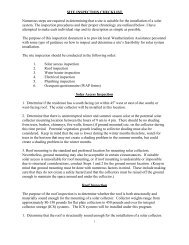
Battery Backup Grid-Connected Photovoltaic Emergency Power System Installation Notes<br />
The following is a brief summary of equipment installation notes. The owner and the installer will be provided<br />
with all manufacturers' instruction manuals as well as a copy of the materials that have been submitted to the <strong>Florida</strong> <strong>Solar</strong><br />
<strong>Energy</strong> Center for design review of the system.<br />
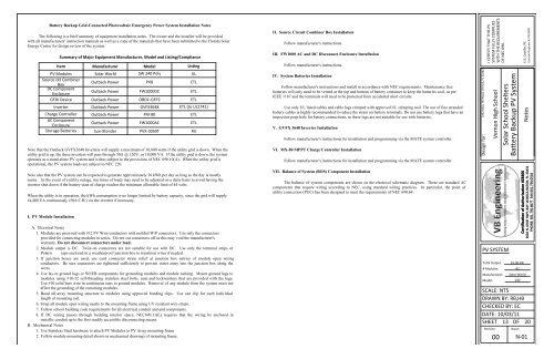
Summary of Major Equipment Manufacturer, Model and Listing/Compliance<br />
Note that the Outback GVFX3648 Inverters will supply a maximum of 10,800 watts if the utility grid is down. When the<br />
utility grid is up, the three inverters will pass through 50A @ 120V, or 18,000 VA. If the utility grid is down, the system<br />
operates as a stand-alone PV system and is thus subject to the provisions of NEC 690.10(A). When the utility grid is<br />
operational, the PV system loads are subject to NEC 220.<br />
Note also that the PV system can be expected to generate approximately 36 kWh per day as long as the day is mostly<br />
sunny. In the event of a utility outage, run times of loads may need to be adjusted on a daily basis to avoid having the<br />
inverter shut down if the battery state of charge reaches the minimum allowable limit of 44 volts.<br />
When the utility is in operation, the kWh consumption is no longer limited by battery capacity, since the grid will supply<br />
14,400 VA continuously (50A C.B.) via the inverter if necessary.<br />
I. PV Module Installation<br />
Item Manufacturer Model Listing<br />
PV Modules <strong>Solar</strong> World SW 240 Poly UL<br />
Source ckt Combiner<br />
Box<br />
DC Component<br />
Enclosure<br />
Outback Power<br />
Outback Power<br />
PV8<br />
FW1000DC<br />
ETL<br />
ETL<br />
GFDI Device Outback Power OBDC-GFP2 ETL<br />
Inverter Outback Power GVFX3648 ETL (to UL1741)<br />
Charge Controller Outback Power FM-80 ETL<br />
AC Component<br />
Enclosure<br />
Outback Power FW1000AC ETL<br />
Storage Batteries Sun-Xtender PVX-3050T ЯU<br />
A. Electrical Notes<br />
1. Modules are prewired with #12 PV Wire conductors with molded W/P connectors. Use only the connectors<br />
provided for connecting modules in series. Do not cut connectors off as this may void the manufacturer's<br />
warranty. Do not disconnect connectors under load.<br />
2. Module output is DC. Twist-on connectors are not suitable for use with DC. Use only the terminal strips or<br />
Polaris taps enclosed in a weatherproof junction box to transition wires if needed.<br />
3. If junction boxes are used, use cord connector strain relief at junction box entries of module open wiring<br />
conductors. Be sure connectors are tightened sufficiently to prevent water entry into the junction box along the<br />
wires.<br />
4. Use lay-in ground lugs or WEEB components for grounding modules and module racking. Mount ground lugs to<br />
modules using #10-32 self-threading stainless steel bolts, nuts and lockwashers that are provided with the lugs.<br />
Use #10 solid bare wire in continuous runs to ground modules. Removal of any module from the system must not<br />
affect the grounding of the remaining modules.<br />
5. Bond all array mounting structure to modules using approved bonding clips. Use one clip for each individual<br />
length of mounting rail.<br />
6. Strap all module open wiring neatly to the mounting frame using UV resistant wire straps.<br />
7. Follow school building code requirements for all electrical conduit and and components.<br />
8. If DC wiring passes through building interior space, NEC690.31(E) requires that the wiring be enclosed in<br />
metallic conduit up to the first readily accessible disconnecting means.<br />
B. Mechanical Notes<br />
1. Use Stainless Steel hardware to attach PV Modules to PV Array mounting frame<br />
2. Follow module mounting detail shown in mechanical drawings of mounting frame.<br />
II. Source Circuit Combiner Box Installation<br />
Follow manufacturer's instructions.<br />
III. FW1000 AC and DC Disconnect Enclosure Installation<br />
Follow manufacturer's instructions.<br />
IV. System Batteries Installation<br />
Follow manufacturer's instructions and install in accordance with NEC requirements. Maintenance free<br />
batteries will only need to be vented at the top and bottom of battery container to keep the batteries cool, as per<br />
IEEE 1187 and the terminals will need to be protected from accidental short circuits.<br />
Use only UL listed cables and cable lugs crimped with approved UL crimping tool. The use of fine stranded<br />
battery cables is highly recommended to reduce the strain on battery terminals. Do not use battery lugs that have an<br />
inspection peep hole for battery connections, as these lugs are not suitable for use with batteries.<br />
V. GVFX 3648 Inverter Installation<br />
Follow manufacturer's instructions for installation and programming via the MATE system controller.<br />
VI. MX-80 MPPT Charge Controller Installation<br />
Follow manufacturer's instructions for installation and programming via the MATE system controller.<br />
VII. Balance of System (BOS) Component Installation<br />
The balance of system components are shown on the electrical schematic diagram. These are standard AC<br />
components that require wiring according to NEC, using standard wiring practices. In particular, the point of<br />
utility connection (PUC) has been designed to meet the requirements of NEC 690.64.<br />
3232 Moss Hill Road, <strong>Vernon</strong>, FL 32462<br />
Design for:<br />
I CERTIFY THAT THIS PV<br />
SYSTEM FULLY COMPLIES<br />
WITH THE REQUIREMENTS<br />
OF NEC 690.<br />
PV SYSTEM<br />
Total Output:<br />
# Modules:<br />
Manufacturer:<br />
Model:<br />
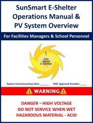
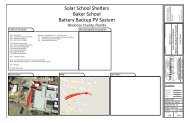
<strong>Vernon</strong> <strong>High</strong> <strong>School</strong><br />
<strong>Solar</strong> <strong>School</strong> Shelters<br />
Battery Backup PV System<br />
Notes<br />
SCALE: NTS<br />
DRAWN BY: RB,HB<br />
CHECKED BY: EC<br />
DATE: 10/03/11<br />
SHEET 13 OF 20<br />
Revision:<br />
00<br />
10.08 kW<br />
42<br />
<strong>Solar</strong> World<br />
240<br />
Sheet:<br />
E.E. Castillo, PE<br />
Licensed Engineer #: PE52590<br />
Certification of Authorization #28406<br />
3601 N. DIXIE HWY, BAY 16 BOCA RATON, FL 33431<br />
PHONE: 561.750.8677 FAX:561.750.0518<br />
N-01