ERB237MSW - Free-Instruction-Manuals.com
ERB237MSW - Free-Instruction-Manuals.com
ERB237MSW - Free-Instruction-Manuals.com

Create successful ePaper yourself
Turn your PDF publications into a flip-book with our unique Google optimized e-Paper software.
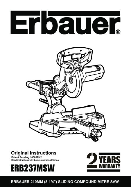
Original <strong>Instruction</strong>s<br />
Patent Pending 1008829.2<br />
Read instructions fully before operating this tool<br />
<strong>ERB237MSW</strong><br />
ERBAUER 210MM (8-1/4”) SLIDING COMPOUND MITRE SAW
ERBAUER 210MM (8-1/4”) SLIDING COMPOUND MITRE SAW
Congratulations on your purchase of a quality power tool from Erbauer Ltd.<br />
This product should give you reliable service for your peace of mind this power<br />
tool does carry a 24-month guarantee, the terms of which are detailed below.<br />
If this product develops a fault within the guarantee period contact your retailer.<br />
Please retain this handbook in case you need to refer to safety, care or guarantee<br />
information in the future.<br />
GUARANTEE<br />
This product carries an Erbauer Ltd guarantee of 24 months. If your product<br />
develops a fault within this period, you should, in the first instance contact your retailer.<br />
If the fault occurs within the first 24 months, you may return the goods for a full refund or<br />
we will repair or replace the goods if you prefer. When repair is not practical or identical<br />
goods are not available, alternative goods of similar specification and quality will usually<br />
be provided but, failing this, you will be offered a partial or full refund depending on the<br />
time period since purchase.<br />
This guarantee specifically excludes losses caused due to:<br />
-Fair wear and tear<br />
-Misuse or abuse<br />
-Lack of routine maintenance<br />
-Failure of consumable items (such as batteries)<br />
-Accidental damage<br />
-Cosmetic damage<br />
-Failure to follow manufacturer’s guidelines<br />
-Loss of use of the goods<br />
-Repairs attempted by anyone, unless authorised by Erbauer Ltd.<br />
This guarantee does not affect your statutory rights. This guarantee is only valid in the UK.<br />
For further technical advice and spare parts, please contact your retailer quoting your<br />
Erbauer model number.<br />
ERBAUER 210MM (8-1/4”) SLIDING COMPOUND MITRE SAW
SAFETY INSTRUCTIONS<br />
WARNING! Read all instructions. Failure to follow all instructions listed below<br />
may result in electric shock, fire and/or serious injury.<br />
SAVE THESE INSTRUCTIONS<br />
The term “power tool” in the warning refers to your mains-operated (corded) power tool<br />
or battery-operated (cordless) power tool.<br />
1. Work area<br />
a. Keep work area clean and well lit. Cluttered and dark areas invite accidents.<br />
b. Do not operate power tools in explosive atmospheres, such as in the presence<br />
of flammable liquids, gases or dust. Power tools create sparks which may ignite the<br />
dust or fumes.<br />
c. Keep children and bystanders away while operating a power tool.<br />
Distractions can cause you to lose control.<br />
2. Electrical safety<br />
a. Power tool plugs must match the outlet. Never modify the plug in any way.<br />
Do not use any adapter plugs with earthed (grounded) power tools.<br />
Unmodified plugs and matching outlets will reduce risk of electric shock.<br />
b. Avoid body contact with earthed or grounded surfaces such as pipes,<br />
radiators, ranges and refrigerators. There is an increased risk of electric shock if your<br />
body is earthed or grounded.<br />
c. Do not expose power tools to rain or wet conditions. Water entering a power tool<br />
will increase the risk of electric shock.<br />
d. Do not abuse the cord. Never use the cord for carrying, pulling or unplugging<br />
the power tool. Keep cord away from heat, oil, sharp edges or moving parts.<br />
Damaged or entangled cords increase the risk of electric shock.<br />
e. When operating a power tool outdoors, use an extension cord suitable for<br />
outdoor use. Use of a cord suitable for outdoor use reduces the risk of electric shock.<br />
f. If operating a power tool in a damp location is unavoidable, use a residual<br />
current device (RCD) protected supply. Use of an RCD reduces the risk<br />
of electric shock.<br />
3. Personal safety<br />
a. Stay alert, watch what you are doing and use <strong>com</strong>mon sense when operating<br />
a power tool. Do not use a power tool while you are tired or under the influence<br />
of drugs, alcohol or medication. A moment of inattention while operating power tools<br />
may result in serious personal injury.<br />
b. Use safety equipment. Always wear eye protection. Safety equipment such as<br />
dust mask, non-skid safety shoes, hard hat, or hearing protection used for appropriate<br />
conditions will reduce personal injuries.<br />
c. Avoid accidental starting. Ensure the switch is in the off-position before<br />
plugging in. Carrying power tools with your finger on the switch or plugging in power<br />
tools that have the switch on invites accidents.<br />
d. Remove any adjusting key or spanner before turning the power tool on. A spanner<br />
or a key left attached to a rotating part of the power tool may result in personal injury.<br />
ERBAUER 210MM (8-1/4”) SLIDING COMPOUND MITRE SAW
e. Do not overreach. Keep proper footing and balance at all times. This enables<br />
better control of the power tool in unexpected situations.<br />
f. Dress properly. Do not wear loose clothing or jewellery. Keep your hair, clothing<br />
and gloves away from moving parts. Loose clothes, jewellery or long hair can be<br />
caught in moving parts.<br />
g. If devices are provided for the connection of dust extraction and collection<br />
facilities, ensure these are connected and properly used. Use of these devices can<br />
reduce dust related hazards.<br />
4. Power tool use and care<br />
a. Do not force the power tool. Use the correct power tool for your application.<br />
The correct power tool will do the job better and safer at the rate for which it was<br />
designed.<br />
b. Do not use the power tool if the switch does not turn it on and off. Any power<br />
tool that cannot be controlled with the switch is dangerous and must be repaired.<br />
c. Disconnect the plug from the power source before making any adjustments,<br />
changing accessories, or storing power tools. Such preventive safety measures<br />
reduce the risk of starting the power tool accidentally.<br />
d. Store idle power tools out of the reach of children and do not allow persons<br />
unfamiliar with the power tool or these instructions to operate the power tool.<br />
Power tools are dangerous in the hands of untrained users.<br />
e. Maintain power tools. Check for misalignment or binding of moving parts,<br />
breakage of parts and any other condition that may affect the power tools<br />
operation. If damaged, have the power tool repaired before use. Many accidents<br />
are caused by poorly maintained power tools.<br />
f. Keep cutting tools sharp and clean. Properly maintained cutting tools with sharp<br />
cutting edges are less likely to bind and are easier to control.<br />
g. Use the power tool, accessories and tool bits etc., in accordance with these<br />
instructions and in the manner intended for the particular type of power tool, taking<br />
into account the working conditions and the work to be performed. Use of the power<br />
tool for operations different from intended could result in a hazardous situation.<br />
5. Service<br />
Have your power tool serviced by a qualified repair person using only identical<br />
replacement parts.<br />
This will ensure that the safety of the power tool is maintained.<br />
HEALTH ADVICE<br />
Warning! When drilling, sanding, sawing or grinding, dust particles will be<br />
produced. In some instances, depending on the materials you are working<br />
with, this dust can be particularly harmful to you (e.g. lead from old gloss paint).You are<br />
advised to consider the risks associated with the materials you are working with and to<br />
reduce the risk of exposure. You should:<br />
-Work in a well-ventilated area.<br />
-Work with approved safety equipment, such as dust masks that are specially designed<br />
to filter microscopic particles.<br />
ERBAUER 210MM (8-1/4”) SLIDING COMPOUND MITRE SAW
Safety instructions for all saws<br />
a. DANGER: Keep hands away from cutting area and the blade. Keep your second<br />
hand on the handle, or motor housing. If both hands are holding the saw, they cannot<br />
be cut by the blade.<br />
b. Do not reach underneath the workpiece. The guard cannot protect you from the<br />
blade below the workpiece.<br />
c. Adjust the cutting depth to the thickness of the workpiece. Less than a full tooth<br />
of the blade teeth should be visible below the workpiece.<br />
d. Never hold piece being cut in your hands or across your leg. Secure the<br />
workpiece to a stable platform. It is important to support the work properly to minimize<br />
body exposure, blade binding, or loss of control.<br />
e. Hold power tool by insulated gripping surfaces when performing an operation<br />
where the cutting tool may contact hidden wiring or its own cord. Contact with<br />
a “live” wire will also make exposed metal parts of the power tool “live” and shock the<br />
operator.<br />
f. When ripping always use a rip fence or straight edge guide. This improves the<br />
accuracy of cut and reduces the chance of blade binding.<br />
g. Always use blades with correct size and shape (diamond versus round) of arbor<br />
holes. Blades that do not match the mounting hardware of the saw will run eccentrically,<br />
causing loss of control.<br />
h. Never use damaged or incorrect blade washers or bolt. The blade washers and bolt<br />
were specially designed for your saw, for optimum performance and safety of operation.<br />
Further safety instructions for all saws<br />
Causes and operator prevention of kickback:<br />
− kickback is a sudden reaction to a pinched, bound or misaligned saw blade, causing an<br />
uncontrolled saw to lift up and out of the workpiece toward the operator;<br />
− when the blade is pinched or bound tightly by the kerf closing down, the blade stalls and<br />
the motor reaction drives the unit rapidly back toward the operator;<br />
− if the blade be<strong>com</strong>es twisted or misaligned in the cut, the teeth at the back edge of the<br />
blade can dig into the top surface of the wood causing the blade to climb out of the kerf<br />
and jump back toward the operator.<br />
Kickback is the result of saw misuse and/or incorrect operating procedures or conditions<br />
and can be avoided by taking proper precautions as given below.<br />
a. Maintain a firm grip with both hands on the saw and position your arms to resist<br />
kickback forces. Position your body to either side of the blade, but not in line with<br />
the blade. Kickback could cause the saw to jump backwards, but kickback forces can be<br />
controlled by the operator, if proper precautions are taken.<br />
b. When blade is binding, or when interrupting a cut for any reason, release the<br />
trigger and hold the saw motionless in the material until the blade <strong>com</strong>es to a<br />
<strong>com</strong>plete stop. Never attempt to remove the saw from the work or pull the saw<br />
backward while the blade is in motion or kickback may occur. Investigate and take<br />
corrective actions to eliminate the cause of blade binding.<br />
c. When restarting a saw in the workpiece, centre the saw blade in the kerf and<br />
check that saw teeth are not engaged into the material. If saw blade is binding, it may<br />
walk up or kickback from the workpiece as the saw is restarted.<br />
ERBAUER 210MM (8-1/4”) SLIDING COMPOUND MITRE SAW
d. Support large panels to minimise the risk of blade pinching and kickback. Large<br />
panels tend to sag under their own weight. Supports must be placed under the panel on<br />
both sides, near the line of cut and near the edge of the panel.<br />
e. Do not use dull or damaged blades. Unsharpened or improperly set blades produce<br />
narrow kerf causing excessive friction, blade binding and kickback.<br />
f. Blade depth and bevel adjusting locking levers must be tight and secure before<br />
making cut. If blade adjustment shifts while cutting, it may cause binding and kickback.<br />
g. Use extra caution when making a “plunge cut” into existing walls or other blind<br />
areas. The protruding blade may cut objects that can cause kickback.<br />
Safety instructions for saws<br />
a. Check the lower guard for proper closing before each use. Do not operate the<br />
saw if the lower guard does not move freely and close instantly. Never clamp or tie<br />
the lower guard into the open position. If saw is accidentally dropped, the lower guard<br />
may be bent. Raise the lower guard with the retracting handle and make sure it moves<br />
freely and does not touch the blade or any other part, in all angles and depths of cut.<br />
b. Check the operation of the lower guard spring. If the guard and the spring are not<br />
operating properly, they must be serviced before use. The lower guard may operate<br />
sluggishly due to damaged parts, gummy deposits, or a build-up of debris.<br />
c. Lower guard may be retracted manually only for special cuts such as “plunge<br />
cuts” and “<strong>com</strong>pound cuts.” Raise the lower guard by retracting handle and as<br />
soon as blade enters the material, the lower guard must be released. For all other<br />
sawing, the lower guard should operate automatically.<br />
d. Always observe that the lower guard is covering the blade before placing saw<br />
down on bench or floor. An unprotected, coasting blade will cause the saw to walk<br />
backwards, cutting whatever is in its path. Be aware of the time it takes for the blade to<br />
stop after switch is released.<br />
ERBAUER 210MM (8-1/4”) SLIDING COMPOUND MITRE SAW
ADDITIONAL SAFETY INSTRUCTIONS FOR YOUR MITRE SAW<br />
Warning: Be sure to read and understand all instructions. Failure to<br />
follow all instructions listed below may result in electric shock, fire and/<br />
or serious personal injury.<br />
1. Know your power tool. Read operator’s manual carefully. Learn the applications<br />
and limitations, as well as the specific potential hazards related to this tool.<br />
2. Always wear safety glasses or eye shields when using this mitre saw. Everyday<br />
eyeglasses have only impact-resistant lenses; they are not safety glasses.<br />
3. Always protect your lungs. Wear a face mask or dust mask if the operation is dusty.<br />
Always use dust extraction equipment to minimise dust.<br />
4. Always protect your hearing. Wear hearing protection during extended periods<br />
of operation.<br />
5. Always inspect the tool cords periodically and if damaged have them repaired.<br />
Always be aware of the cord location.<br />
6. Always check for damaged parts. Before further use of the tool, a guard or<br />
other part that is damaged should be carefully checked to determine if it will<br />
operate properly and perform its intended function. Check for misalignment or<br />
binding of moving parts, breakage of parts, and any other condition that may<br />
affect the tool’s operation. A guard or other part that is damaged should be<br />
properly repaired or replaced at a qualified service centre.<br />
7. Do not abuse the cord. Never use the cord to carry the tools or pull the plug from<br />
the outlet. Keep cord away from heat, oil, sharp edges or moving parts. Replace<br />
damaged cords immediately. Damaged cords increase the risk of electric shock.<br />
8. Always make sure that your extension cord is in good condition. When using<br />
an extension cord be sure to use one that is heavy enough to carry the current<br />
that your tool will draw. An undersized cord will cause a drop in line voltage,<br />
resulting in loss of power and overheating.<br />
9. Always inspect and remove all nails from lumber before sawing.<br />
10. Do not use the tool while tired or under the influence of drugs, alcohol or any<br />
medication. Following this rule will reduce the risk of electric shock, fire or serious<br />
personal injury.<br />
11. Save these instructions. Refer to them frequently and use them to instruct<br />
others who may use this tool. If someone borrows this tool, make sure they have<br />
these instructions also.<br />
ERBAUER 210MM (8-1/4”) SLIDING COMPOUND MITRE SAW
12. When the correct blade to cut the material has been fitted, this saw is<br />
re<strong>com</strong>mended for cutting wood, non-ferrous metal and plastic only.<br />
13. Do not use saw blades with High Speed Steel (HSS) or damaged or deformed<br />
blades.<br />
14. Replace the table insert when worn.<br />
15. Use only saw blades re<strong>com</strong>mended by the manufacturer and which have the<br />
exact bore and diameter required for this machine.<br />
16. Connect your mitre saw to a dust collecting device (I. D.Ø32mm) when sawing.<br />
17. Select saw blades in relation to the material to be cut.<br />
18. Check the maximum depth of cut.<br />
19. When sawing long work pieces, always use extra support to provide better<br />
support, and use clamps or other clamping devices.<br />
20. The operator is adequately trained in the use, adjustment and operation and<br />
operation of the machine.<br />
21. Provide for adequate room lighting at your workplace or for adequate lighting<br />
of the immediate work area.<br />
22. When fitted with laser no exchange with different type of laser is permitted.<br />
Repairs shall only be carried out by the laser manufacturer or an authorised<br />
agent.<br />
23. Refrain from removing any cut-offs or other parts of the workpiece from<br />
the cutting area whilst the machine is running and the saw head is not the rest<br />
position.<br />
24. Never stand on this tool. Serious injuries could occur when this tool tips over<br />
or when <strong>com</strong>ing in contact with the saw blade.<br />
WARNING: the operation of any mitre saw can result in foreign objects being<br />
thrown into your eyes, which can result in severe eye damage. Before beginning<br />
power tool operation, always wear safety goggles or safety glasses with side shield and a<br />
full face shield when needed.<br />
Warning: If any parts are missing, do not operate your mitre saw until the<br />
missing parts are replaced. Failure to follow this rule could result in serious<br />
personal injury.<br />
Caution: Do not let familiarity with your mitre saw make you careless. Remember that a<br />
careless fraction of a second is sufficient to cause severe injury.<br />
ERBAUER 210MM (8-1/4”) SLIDING COMPOUND MITRE SAW
Double insulation:<br />
The tool is double insulated. This means that all the external metal parts are electrically<br />
insulated from the mains power supply. This is done by placing insulation barriers<br />
between the electrical and mechanical <strong>com</strong>ponents making it unnecessary for the tool<br />
to be earthed.<br />
Important note<br />
Be sure the supply is the same as the voltage given on the rating plate. The tool is fitted<br />
with a two-core cable and plug. Remove the mains plug from socket before carrying out<br />
any adjustment or servicing.<br />
SPECIFIC SAFETY RULES & SYMBOLS<br />
WARNING!<br />
Do not operate machine if warning and / or instruction labels are missing or damaged.<br />
Symbol Description<br />
V Volts<br />
A Amperes<br />
Hz Hertz<br />
Min-1 Speed<br />
~ Alternating Current<br />
No No Load Speed<br />
Double Insulated<br />
Wear Safety Goggles<br />
Wear Ear Protection<br />
Wear Dust Mask<br />
Read <strong>Instruction</strong> Manual<br />
Laser Warning Symbol<br />
Conforms to relevant<br />
safety standards<br />
General Warning<br />
ERBAUER 210MM (8-1/4”) SLIDING COMPOUND MITRE SAW
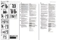
KNOW YOUR SLIDING MITRE SAW<br />
Fig 1<br />
1. DUST BAG<br />
2. UPPER BLADE GUARD<br />
3. CUTTING HANDLE<br />
4. LOWER BLADE GUARD<br />
5. BLADE<br />
6. TABLE INSERT<br />
7. MITRE HANDLE<br />
8. BEVEL LOCK HANDLE<br />
9. BASE<br />
10. TURNTABLE<br />
11. LEFT EXTENSION TABLE<br />
12. FENCE<br />
13. HOLD-DOWN CLAMP<br />
14. SLIDE CARRIAGE LOCK KNOB<br />
8<br />
14<br />
1<br />
11<br />
2<br />
10<br />
ERBAUER 210MM (8-1/4”) SLIDING COMPOUND MITRE SAW<br />
6<br />
9<br />
5<br />
4<br />
3<br />
12<br />
13<br />
7
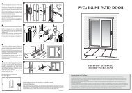
Fig 2<br />
21<br />
20<br />
15. CARRYING HANDLE<br />
16. SLIDE CARRIAGE<br />
17. LASER GUIDE<br />
18. RIGHT EXTENSION TABLE<br />
19. MOTOR<br />
20. POSITIVE STOP LOCKING LEVER<br />
21. LOWER BLADE GUARD LOCK LEVER<br />
22. LASER ON/OFF SWITCH<br />
23. ADJUSTABLE CUTTING STOP<br />
ERBAUER 210MM (8-1/4”) SLIDING COMPOUND MITRE SAW<br />
19<br />
22<br />
18<br />
17<br />
16<br />
15<br />
23
TECHNICAL DATA<br />
Volts: 230V~50Hz<br />
Power input: 1400W<br />
No-load speed: 5000min-1 Double insulation:<br />
Net weight: 13.8 kg<br />
Blade: Ø210 mm ; Ø30 mm Bore<br />
Turntable Ø295 mm<br />
Mitre stops 0°,15°, 22.5°, 31.6°, 45° left & right<br />
Mitre angle range 45° left & right<br />
Bevel angle range 0° to 47° left<br />
Maximum capacity<br />
Cross cut: 63mm x 233mm<br />
Mitre cut at 45°: 46mm x 233mm<br />
Bevel cut at 45°: 63mm x 117mm<br />
Compound cut at 45°: 46mm x 117mm left<br />
NOISE AND VIBRATION DATA<br />
Sound pressure level LPA: 94 dB(A) (K=3dB(A))<br />
Sound power level LWA: 107 dB(A) (K=3dB(A))<br />
Vibration level: 3.384m/s2 (K=1.5m/s2 )<br />
- The declared vibration total value has been measured in accordance with a standard<br />
test method and may be used for <strong>com</strong>paring one tool with another.<br />
- The declared vibration total value may also be used in a preliminary assessment of<br />
exposure.<br />
WARNING: The vibration emission during actual use of the power tool can differ from<br />
the declared total value depending on the ways in which the tool is used; and of the<br />
need to identify safety measures to protect the operator that are based on an estimation<br />
of exposure in the actual conditions of use (taking account of all parts of the operating<br />
cycle such as the times when the tool is switched off and when it is running idle in<br />
addition to the trigger time).<br />
ACCESSORIES<br />
Allen Key 1 pc, Dust Bag 1 pc, Hold-Down Clamp 1 pc & Mitre Handle 1 pc<br />
ERBAUER 210MM (8-1/4”) SLIDING COMPOUND MITRE SAW
VIBRATION<br />
The European Physical Agents (Vibration) Directive has been brought in to help reduce<br />
hand arm vibration syndrome injuries to power tool users. The directive requires power<br />
tool manufacturers and suppliers to provide indicative vibration test results to enable<br />
users to make informed decisions as to the period of time a power tool can be used<br />
safely on a daily basis and the choice of tool.Further Advice can be found<br />
at www.hse.gov.uk<br />
Vibration total values (triax vector sum) determined according to EN 61029<br />
Test specification; Standard = EN61029-1 2009. Vibration emission value ah = 3.384m/s²<br />
Test prodcure GS mark.<br />
Uncertainty K = 1.5m/s²<br />
The declared vibration emission value should be used as a minimum level should be used with the<br />
current guidance on vibration.<br />
Calculating the actual period of the actual period off use can be difficult and the HSE website has<br />
further information.<br />
The declared vibration emission been measured in accordance with a standardised test stated above<br />
and may be used to <strong>com</strong>pare one tool with another.<br />
The declared vibration emission value may also be used in a preliminary assessment of exposure.<br />
Warning: The vibration emission value during actual use of the power tool can differ<br />
from the declared value depending on the ways in which the tool is used<br />
dependant on the following examples and other variations on how the tool is used:-<br />
How the tool is used and the materials being cut or drilled.<br />
The tool being in good condition and well maintained<br />
The use the correct accessory for the tool and ensuring it is sharp and in good condition.<br />
And the tool is being used as intended by its design and these instructions.<br />
This tool may cause hand-arm vibration syndrome<br />
if its use is not adequately managed<br />
Warning: identify safety measures to protect the operator that are based on an<br />
estimation of exposure in the actual conditions of use (taking account of all parts<br />
of the operating cycle such as the times when the tool is switched off and when it is<br />
running idle in addition to the trigger time).Note The use of other tools will reduce the<br />
users’ total working period on this tool. Helping to minimise your vibration exposure risk.<br />
ALWAYS use sharp chisels, drills and blades. Maintain this tool in accordance with these instructions<br />
and keep well lubricated (where appropriate)<br />
Avoid using tools in temperatures of 10C or less<br />
Plan your work schedule to spread any high vibration tool use across a number of days.<br />
Health Surveillance<br />
All employees should be part of an employer’s health surveillance scheme to help identity<br />
any vibration related diseases at an early stage, prevent disease progression and<br />
help employees stay in work.<br />
ERBAUER 210MM (8-1/4”) SLIDING COMPOUND MITRE SAW
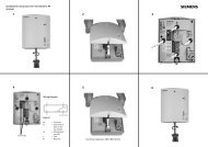
Fig 3<br />
Fig 4<br />
Fig 5<br />
2<br />
1<br />
1<br />
3<br />
1<br />
ASSEMBLY INSTRUCTIONS<br />
Warning: To avoid injury, do not connect<br />
this mitre saw to the power source until<br />
it is <strong>com</strong>pletely assembled and adjusted and you<br />
have read and understood this Operator’s Manual.<br />
1. Installing the mitre handle<br />
1) Thread the mitre handle (1) into the hole located<br />
at the front of the mitre table. (See fig. 3)<br />
2. Unlocking the slide carriage<br />
After removing the saw from the carton, loosen<br />
the slide carriage lock knob (1). When transporting<br />
or storing the mitre saw, the slide carriage should<br />
always be locked in position. The slide carriage<br />
lock knob (1) is located on the side of the slide<br />
carriage. (See fig. 4)<br />
3. Raising the Cutting Head<br />
1) Push down slightly on the switch handle (1) and<br />
the lock lever (2).<br />
2) Pull out the stop latch knob (3).<br />
3) Allow the cutting head to rise to the up position.<br />
(See fig. 5)<br />
Warning: To avoid injury and damage<br />
to the saw, transport and store the<br />
mitre saw with the cutting head locked in the<br />
down position. Never use the stop latch to hold<br />
the cutting head in a down position for cutting<br />
operations.<br />
Locking<br />
When transporting or storing the mitre saw, the cutting<br />
head should always be locked in the down position.<br />
1) Push the lock lever (2) and cutting head down<br />
to its lowest position.<br />
2) Push the stop latch knob (3) into the locking hole.<br />
IMPORTANT<br />
To avoid damage, never carry the mitre saw by the<br />
cutting arm or the mitre handle. ALWAYS use both<br />
designated carrying handles together.<br />
ERBAUER 210MM (8-1/4”) SLIDING COMPOUND MITRE SAW
4. Installing the dust bag<br />
1) Squeeze the metal collar wings (2) of the dust<br />
bag (1).<br />
2) Place the dust bag neck opening around the<br />
exhaust port (3), and release the metal collar<br />
wings. (See fig. 6)<br />
5. Installing the hold-down clamp<br />
1) Loosen the lock knob (1) from the rear side of<br />
the saw base (2). (See fig. 7)<br />
2) Place the hold-down clamp assembly (3) in<br />
one of the mounting holes (4). (See fig. 8)<br />
3) Tighten the lock knob (1). (See fig. 7)<br />
Warning: When using stop block on<br />
the right side, hold-down clamp must<br />
also be in right side. Using hold-down clamp<br />
on the left side during this operation can cause<br />
kickback and serious injury to the operator.<br />
Fig 6<br />
Fig 7<br />
Fig 8<br />
ERBAUER 210MM (8-1/4”) SLIDING COMPOUND MITRE SAW<br />
1<br />
4 4<br />
2<br />
3<br />
3<br />
1<br />
2
Fig 9<br />
Fig 10<br />
5<br />
1) Hex headed bolt<br />
2) Flat washer<br />
3) Rubber washer<br />
4) Mitre saw base<br />
5) Workbench<br />
6) Flat washer<br />
7) Lock washer<br />
8) Hex nut<br />
9) Lock nut<br />
4<br />
6<br />
7<br />
3<br />
1<br />
2<br />
8<br />
9<br />
6. Mounting the mitre saw<br />
Warning: To avoid injury from unexpected<br />
saw movement:<br />
<br />
lock the cutting head in the lower position using<br />
the stop latch.<br />
<br />
slide carriage lock knob.<br />
<br />
designated carrying handles located on the top of<br />
the machine. When lifting, bend at your knees, not<br />
from your back.<br />
<br />
or by the switch handle. Carrying the tool by the<br />
power cord could cause damage to the insulation<br />
or the wire connections resulting in electric shock<br />
or fire.<br />
<br />
visitors to stand near the saw during any cutting<br />
operation.<br />
<br />
<br />
Mounting instructions<br />
1) For stationary use, place the saw in the desired<br />
location, directly on a workbench where there<br />
is room for handling and proper support of the<br />
workpiece. The base of the saw has four mounting<br />
holes. Bolt the base of the mitre saw (1) to the<br />
work surface (5),using the fastening method as<br />
shown in Fig 9.<br />
2) For portable use, place the saw on a<br />
20mm(approx) thick piece of plywood. Bolt the<br />
base of the mitre saw securely to the plywood<br />
using the mounting holes on the base. Use<br />
G-clamps to clamp this mounting board to a stable<br />
work surface at the worksite. (See fig. 10)<br />
Note: Mounting hardware is not included with this<br />
tool. Bolts, nuts, washers and screws must be<br />
purchased separately.<br />
ERBAUER 210MM (8-1/4”) SLIDING COMPOUND MITRE SAW
7. Removing and installing the blade<br />
Warning:<br />
<br />
than 255 mm in diameter.<br />
<br />
sure the switch is in the OFF position and the<br />
plug is not connected to the power source outlet.<br />
<br />
figs13 and 14. We re<strong>com</strong>mend that the operator<br />
considers wearing protective gloves when<br />
handling or installing the blade.<br />
Removing blade<br />
1) Unplug the saw from the outlet.<br />
2) The slide carriage should be locked in position<br />
by tightening the slide carriage lock knob (1).<br />
(See fig. 11)<br />
3) Allow the cutting head to rise to the upright<br />
position. (See fig. 11)<br />
4) Release the lower blade guard by operating<br />
the blade guard handle, and rotate the guard into<br />
its upper position.<br />
5) Locate the arbor lock (1). (See fig. 12)<br />
6) Hold the guard in position with your thumb and<br />
press the arbor lock gently with a finger. (See fig.<br />
13)Rotate the blade using the correct sized hex<br />
key inserted into the arbor bolt (See fig. 14) until<br />
positive location is felt.<br />
7) Keeping the arbor lock firmly pressed undo<br />
the arbor bolt with the hex key by turning it in a<br />
clockwise direction.<br />
8) Remove the bolt and outer blade collar from<br />
the machine.<br />
9) With the arbor bolt and out blade collar<br />
removed, gently ease the blade from the arbor<br />
and remove downwards and away from the<br />
cutting head.<br />
Note: Pay attention to the pieces removed,<br />
noting their position and direction they face. Wipe<br />
the blade collars clean of any sawdust before<br />
installing a new blade.<br />
Fig 11<br />
Fig 12<br />
Fig 13<br />
Fig 14<br />
ERBAUER 210MM (8-1/4”) SLIDING COMPOUND MITRE SAW<br />
1<br />
1
Fig 15<br />
8. Installing Blade<br />
Unplug the mitre saw before changing/installing<br />
the blade.<br />
Note: Ensure that the saw blade bore is exactly<br />
the correct size for this machine and the diameter<br />
does not exceed 255 mm.<br />
1) Rotate and hold lower blade guard in its upper<br />
position as already described.<br />
2) Install a 255 mm blade with 30 mm arbor, making<br />
sure the rotation arrow on the blade matches the<br />
clockwise rotation arrow on the upper guard and the<br />
blade teeth are pointing downward.<br />
3) Place the outer blade collar against the blade<br />
and on the arbor. Thread the arbor bolt onto the<br />
arbor in a counterclockwise direction. (See fig. 15)<br />
IMPORTANT<br />
<br />
<br />
4) Place the hex key into the arbor bolt.<br />
5) Press the arbor lock, holding gently while<br />
turning the blade counterclockwise. When arbor<br />
lock engages, continue to press it in firmly while<br />
tightening the arbor bolt securely. (See fig. 14)<br />
Note: Do not press arbor lock when blade<br />
is moving.<br />
Warning: Be sure that the arbor lock<br />
is released so that the blade turns freely.<br />
Lower the blade into the lower table and check<br />
for any contact with the base or the mitre table<br />
by spinning the blade manually. Make sure the<br />
collars are clean and properly arranged. Check<br />
that the lower blade guard is functioning correctly<br />
and does not bind or stick.<br />
ERBAUER 210MM (8-1/4”) SLIDING COMPOUND MITRE SAW
9. Aligning the laser beam<br />
Warning: For your own safety, never<br />
connect the plug to power source<br />
outlet until all the adjustment steps are<br />
<strong>com</strong>plete and you have read and understood<br />
the safety and operational instructions. The<br />
laser beam must always be correctly aligned<br />
with the blade to ensure straight, even cutting.<br />
Your tool is equipped with the Laser guide<br />
cutting guide using a Class II laser beam.<br />
The laser beam will enable the operator to<br />
preview the saw blade path on the stock to be<br />
cut before starting the saw. This laser guide<br />
is powered by the transformed alternating<br />
current supply directly through the power lead.<br />
The saw must be connected to the power<br />
source and the laser on/off switch must be<br />
turned on for the laser line to show.<br />
(See fig.16)<br />
Warning: AVOID DIRECT<br />
EYE CONTACT<br />
Laser radiated when laser guide is turned on.<br />
Avoid direct eye contact. Always unplug the<br />
mitre saw from power source before making<br />
any adjustments.<br />
Laser Warning Label: Max output
Fig 17<br />
Fig 18<br />
Fig 19<br />
2<br />
1<br />
1<br />
3<br />
2<br />
Three laser module mounting/adjustment screws<br />
are provided. Two (1,2) are positioned on the LH<br />
side of the laser housing, and one (3) on the RH<br />
side of the laser housing. These screws gently<br />
hold the laser module in place and on alignment<br />
by bearing on the laser modules casing. It is<br />
important that during any adjustment the pressure<br />
on the laser module casing is maintained as<br />
closely as possible to the factory setting. Do not<br />
over tighten any one screw – damage to the laser<br />
casing could result. (See fig. 17&18)<br />
Carefully remove the laser housings plastic<br />
window by pushing the two attachment lugs(1)<br />
from the rear. This will enable access to the laser<br />
module. (See fig. 19)<br />
B Adjusting the Angle of the Laser Guide<br />
1) Loosen the single screw on the RH side of the<br />
laser housing ½ a turn.<br />
2)Turn the laser element in the desired direction<br />
to adjust the laser angle.<br />
3)Retighten the adjustment screw.<br />
C Aligning the Laser Beam<br />
1)Use the two adjusting screws on the LH side of<br />
the laser housing.<br />
2)Adjust both screws until laser alignment is<br />
achieved.<br />
Warning: Use only the correct sized<br />
hex key when adjusting these screws.<br />
Turn one screw at a time and only ¼ turn in<br />
either direction before checking laser alignment.<br />
Maintain as far as possible the original factory<br />
pressure setting that these screws exert on the<br />
laser module.<br />
ERBAUER 210MM (8-1/4”) SLIDING COMPOUND MITRE SAW
ADJUSTMENT INSTRUCTIONS<br />
1. Bevel stop adjustment<br />
Warning: To avoid injury from an<br />
accidental start, make sure the switch is<br />
in the OFF position and the plug is not connected<br />
to the power source outlet.<br />
2. 90° (0°) Bevel adjustment<br />
1) Loosen bevel lock handle (1) and rotate the<br />
cutting arm <strong>com</strong>pletely to the right until it stops<br />
against the vertical stop. Tighten the bevel lock<br />
handle.<br />
2) Place a <strong>com</strong>bination square (2) on the mitre<br />
table with the ruler against the table and the heel<br />
of the square against the saw blade.<br />
3) If the blade is not 90° (0°) square with the mitre<br />
table (5), loosen the bevel lock handle (1), tilt the<br />
cutting head to the left, loosen the locknut (4) on<br />
the bevel angle adjustment bolt (3) and use an hex<br />
key to adjust the socket headed stop bolt (3) depth<br />
in or out to increase or decrease the bevel angle.<br />
4) Tilt the cutting arm to back to the right at 90°<br />
(0°) bevel and recheck for alignment.<br />
5) Repeat steps 1 through 4 if further adjustment<br />
is needed.<br />
6) Tighten bevel lock handle (1) and locknut (4)<br />
when alignment is achieved. (See fig. 20)<br />
Fig 20<br />
1<br />
4<br />
3<br />
2<br />
5<br />
ERBAUER 210MM (8-1/4”) SLIDING COMPOUND MITRE SAW
Fig 21<br />
3<br />
Fig 22<br />
Fig 23<br />
1<br />
2<br />
2<br />
3<br />
1<br />
1<br />
2<br />
3<br />
2<br />
4<br />
3<br />
3. Bevel pointer adjustment<br />
1) When the blade is exactly 90° (0°) to the table,<br />
loosen the bevel indicator screw (1) using<br />
a # 2 Phillips screwdriver.<br />
2) Adjust bevel indicator (2) to the “0°” mark on<br />
the bevel scale and retighten the screw.<br />
(See fig. 21)<br />
4. Bevel adjustment 45°<br />
1) Loosen the bevel lock handle (1) and tilt the<br />
cutting head <strong>com</strong>pletely to the left.<br />
2) Using a <strong>com</strong>bination square, check to see if<br />
the blade angle is 45° to the table.<br />
3) If the blade is not at 45° to the mitre table, tilt<br />
the cutting arm to the right, loosen the locknut (2)<br />
on the bevel angle adjustment bolt (3) and use an<br />
hex key to adjust the stop bolt (3) depth in or out<br />
to increase or decrease the bevel angle.<br />
4) Tilt the cutting arm to the left to 45° bevel and<br />
recheck for alignment.<br />
5) Repeat steps 1 through 4 until the blade is at<br />
45° to the mitre table.<br />
6) Tighten bevel lock handle (1) and locknut (2)<br />
when alignment is achieved. (See fig. 22)<br />
5. Bevel Setting for Crown Moulding<br />
The cutting arm can also be set at 33.9° for<br />
cutting crown mouldings.<br />
1) Twist and deploy sprung-loaded crown<br />
moulding pin (2).<br />
2) Loosen the bevel lock handle (1) and rotate<br />
the cutting head in the required direction until it<br />
indexes with the moulding pin (2). Tighten the<br />
bevel lock. (See fig. 23)<br />
ERBAUER 210MM (8-1/4”) SLIDING COMPOUND MITRE SAW
6. Bevel adjustment 33.9 o<br />
If necessary the 33.9° settings can be checked<br />
and adjusted. A vernier angle gauge will be<br />
required and this must be accurately set to 33.9°<br />
1) Set the cutting head to 33.9° by deploying the<br />
crown moulding pin. Check the angle of the blade<br />
against the machine table using the vernier angle<br />
gauge. (See fig. 24)<br />
2) If adjustment is required loosen the locknut (3)<br />
to the relevant socket headed stop screw. Adjust<br />
the screw in or out until the correct bevel angle is<br />
achieved. Retighten the locknut. (See fig. 23)<br />
7. Mitre angle adjustment<br />
The sliding <strong>com</strong>pound mitre saw scale can be<br />
easily read, showing mitre angles from 0° to 45°<br />
to the left, and 0° to 45° to the right. The mitre<br />
saw table has nine of the most <strong>com</strong>mon angle<br />
settings with positive stops at 0°, 15°, 22.5°,<br />
31.6°, and 45°. These positive stops position the<br />
blade at the desired angle quickly and accurately.<br />
Follow the process below for quickest and most<br />
accurate adjustments.<br />
1) Unlock the mitre table by turning the mitre<br />
handle (1) counterclockwise.<br />
2) Move the turntable while lifting up on the<br />
positive stop locking lever (2) to align the indicator<br />
(3) to the desired degree measurement.<br />
3) If the desired angle is one of the nine positive<br />
stops, release the positive stop locking lever,<br />
making sure the lever snaps into position, and<br />
then secure by tightening the mitre handle.<br />
4) If the mitre angle desired is not one of the<br />
nine positive stops, simply lock the mitre table<br />
into position by turning the mitre handle in the<br />
clockwise direction. (See fig. 25)<br />
8. Mitre scale indicator adjustment<br />
1) Move the table to the 0° positive stop.<br />
2) Loosen the screw (4) that holds the indicator<br />
with a Phillips screwdriver.<br />
3) Adjust the indicator (3) to the 0° mark and<br />
retighten screw. (See fig. 25)<br />
Fig 24<br />
Fig 25<br />
ERBAUER 210MM (8-1/4”) SLIDING COMPOUND MITRE SAW<br />
1<br />
2<br />
4<br />
3
Fig 26<br />
Fig 27<br />
1<br />
3<br />
2<br />
1<br />
1<br />
3 2<br />
9. Adjusting fence squareness<br />
1) Loosen the four fence locking bolts (1).<br />
2) Lower the cutting arm and lock in position.<br />
3) Using a square (3), lay the heel of the square<br />
against the blade and the ruler against the fence(2)<br />
as shown.<br />
4) Adjust the fence 90° to the blade and tighten the<br />
four fence locking bolts. (See fig. 26)<br />
Caution: If the saw has not been used recently,<br />
recheck blade squareness to the fence and<br />
readjust if needed.<br />
5) After fence has been aligned, using a scrap<br />
piece of wood, make a cut and check<br />
‘squareness’ of the cut in the piece. Readjust if<br />
necessary.<br />
10. Setting cutting depth<br />
The depth of cut can be preset for even and<br />
repetitive shallow cuts.<br />
1) Adjust the cutting head down (See CUTTING<br />
HEAD section) until the teeth of the blade are at<br />
the desired depth.<br />
2) While holding the upper arm in that position, turn<br />
the stop knob (1) until it touches the stop plate (2).<br />
3) Recheck the blade depth by moving the cutting<br />
head front to back through the full motion of a<br />
typical cut along the control arm. (See fig. 27)<br />
11. Adjusting cutting depth<br />
The maximum depth travel of the cutting head was<br />
set at the factory. Check to see that the blade does<br />
not extend more than 6.35 mm below the table<br />
insert, and does not touch the control arm throat<br />
or any part of the base or table. If the maximum<br />
depth needs readjusting:<br />
1) Loosen the depth control screw locknut (3).<br />
2) Pull the cutting head down until it indexes with the<br />
depth control screw.<br />
3) Adjust the depth control screw until the blade<br />
extends 6.35mm below the table insert.<br />
4) Recheck the blade depth by moving the cutting<br />
head front to back through the full motion of a<br />
cut along the control arm. If the blade touches<br />
the inside of the control arm, readjust the setting.<br />
Tighten the locknut when the correct setting is<br />
achieved.(See fig. 27)<br />
ERBAUER 210MM (8-1/4”) SLIDING COMPOUND MITRE SAW
OPERATION INSTRUCTIONS<br />
Warning: Before using your mitre<br />
saw be sure to read the instruction<br />
manual carefully.<br />
Operating instructions<br />
1. Know your mitre saw<br />
Read and understand the Operator’s Manual<br />
and labels affixed to the tool. Learn its<br />
application and limitations as well as the<br />
potential hazards specific to this tool. To avoid<br />
injury from accidental contact with moving parts,<br />
do not lay out, assemble or set up work on the<br />
mitre saw.<br />
2. Electrical connection<br />
Your mitre saw has a precision-built electric<br />
motor and it should only be connected to a<br />
240 V. 50Hz. Power supply (normal household<br />
current). Do not operate on direct current (DC).<br />
This large voltage drop will cause a loss of<br />
power that will overheat the motor. If your mitre<br />
saw does not operate when plugged into an<br />
outlet, have a professional electrician check the<br />
power supply.<br />
Warning: Avoid accidental starting.<br />
Make sure the switch is in the OFF<br />
position before plugging the mitre saw into a<br />
power outlet.<br />
3. Body and Hand position<br />
Warning: Never place hands near the<br />
cutting area. Proper positioning of your<br />
body and hands when operating the mitre saw<br />
will make cutting easier and safer. Keep children<br />
away. Keep all visitors at a safe distance from the<br />
mitre saw. Make sure bystanders are clear of the<br />
saw and workpiece. Don’t force the saw. It will do<br />
the job better and safer at its designed rate.<br />
Starting a cut:<br />
<br />
blade – out of the “no-hands zone” (1). (See Fig 28)<br />
<br />
prevent movement toward the blade.<br />
Fig 28<br />
No-Hands Zone<br />
ERBAUER 210MM (8-1/4”) SLIDING COMPOUND MITRE SAW<br />
1
Fig 29<br />
Fig 30<br />
1<br />
2<br />
1<br />
<br />
down to the workpiece to see the cutting path of<br />
the blade<br />
<br />
<br />
downward motion.<br />
Finishing a cut:<br />
<br />
<br />
parts to stop before moving your hands and<br />
raising the cutting arm.<br />
Before releasing jammed material:<br />
<br />
<br />
<br />
4. Basic saw operations<br />
Warning: For your convenience, your<br />
saw has a blade brake. The brake is not<br />
a safety device. Never rely on it to replace the<br />
proper use of the guard on your saw. If the blade<br />
doesn’t stop within approximately 8 seconds,<br />
wait for the blade to stop, unplug the saw and<br />
contact customer service.<br />
To turn saw on<br />
Push down the lock lever (1) and squeeze the<br />
trigger switch (2) to turn the mitre saw ON.<br />
Release the trigger switch to turn the saw OFF.<br />
(See fig. 29)<br />
5. Sliding carriage system<br />
1) For chop cutting operations on small<br />
workpieces, slide the cutting head assembly<br />
<strong>com</strong>pletely toward the rear of the unit and tighten<br />
the carriage lock knob (1).<br />
2) To cut wide boards up to 310 mm, the carriage<br />
lock knob must be loosened to allow the cutting<br />
head to slide freely. (See fig. 30)<br />
Before leaving the saw<br />
<br />
power OFF. Wait for all moving parts to stop.<br />
<br />
Disconnect master switches. Store tool away<br />
from children and other unqualified users.<br />
ERBAUER 210MM (8-1/4”) SLIDING COMPOUND MITRE SAW
Warning: To avoid injury from<br />
materials being thrown, always unplug<br />
the saw to avoid accidental starting, and remove<br />
small pieces of material from the table cavity.<br />
6. Mitre cut<br />
1) When a mitre cut is required, unlock the<br />
mitre table by turning the mitre handle (1)<br />
counterclockwise.<br />
2) While holding the mitre handle, lift up on the<br />
positive stop locking lever (2).<br />
3) Rotate the mitre table to the right or left with<br />
the mitre handle.<br />
4) When the table is in the desired position,<br />
as shown on the mitre scale (3), release the<br />
positive stop locking lever and tighten the mitre<br />
handle. The table is now locked at the desired<br />
angle. Positive stops are provided at 0°, 15°,<br />
22.5°, 31.6° and 45°. (See fig. 31)<br />
IMPORTANT<br />
Always tighten the mitre table lock handle before<br />
performing every cutting operation.<br />
7. Bevel cut<br />
1) When a bevel cut is required, loosen the<br />
bevel lock handle (1) by turning it clockwise.<br />
2) Tilt the cutting head to the desired angle, as<br />
shown on the bevel scale (2)<br />
3) The blade can be positioned at any angle,<br />
from a 90° straight cut (0° on the scale) to a 45°<br />
left bevel. Tighten the bevel lock handle (1) to<br />
lock the cutting head in position. Positive stops<br />
are provided at 0°, 33.9° and 45°. (See fig. 32)<br />
Note: When cutting at 45 degrees, ensure guard<br />
does not catch on work or machine base plate.<br />
Fig 31<br />
Fig 32<br />
ERBAUER 210MM (8-1/4”) SLIDING COMPOUND MITRE SAW<br />
3<br />
2<br />
2<br />
1<br />
1
Fig 33<br />
Fig 34<br />
3<br />
2<br />
1<br />
3<br />
1<br />
2<br />
4<br />
8. Compound cut<br />
A <strong>com</strong>pound cut is the <strong>com</strong>bination of a mitre and<br />
a bevel cut simultaneously.<br />
1) Loosen the bevel lock handle (1) and position<br />
the cutting head at the desired bevel position.<br />
Lock the bevel lock handle.<br />
2) Loosen the mitre handle (2). Press down the<br />
positive stop locking lever (3) and position the<br />
table at the desired angle. Release the positive<br />
stop locking lever and lock the mitre handle. (See<br />
fig. 33)<br />
9. Slide cutting wide boards up to 305 mm wide<br />
Warning:<br />
To avoid injury:<br />
<br />
spinning blade toward you during the cut. The<br />
blade may try to climb up on the top of the<br />
workpiece, causing the cutting assembly and<br />
spinning blade to kick back, forcefully. The cutting<br />
head assembly should be drawn back <strong>com</strong>pletely<br />
then pushed forward when sawing.<br />
<br />
will help reduce the risk of a thrown workpiece.<br />
To slide cut wide boards<br />
1) Unlock the carriage lock handle (1) and allow<br />
the cutting head assembly to move freely.<br />
2) Set both the desired bevel angle and/or the<br />
mitre angle and lock into position.<br />
3) Use a hold down clamp to secure the<br />
workpiece.<br />
4) Grasp the switch handle (2) and pull the<br />
carriage (3) forward until the centre of the saw<br />
blade is over the front of the workpiece (4).<br />
5) Engage the trigger to turn the saw on.<br />
6) When the saw reaches full speed, push the<br />
switch handle down, slowly, cutting through the<br />
leading edge of the workpiece.<br />
7) Slowly move the switch handle toward the<br />
fence, <strong>com</strong>pleting the cut.<br />
8) Release the trigger and allow the blade to stop<br />
spinning before allowing the cutting head to raise<br />
to its upper position. (See fig. 34)<br />
ERBAUER 210MM (8-1/4”) SLIDING COMPOUND MITRE SAW
10. Cutting bowed material<br />
A bowed workpiece must be positioned against<br />
the fence and secured with a clamping devise<br />
before cutting as shown.<br />
Warning: Do not position workpiece<br />
incorrectly or try to cut the workpiece<br />
without the support of the fence. (See fig. 35)<br />
This will cause the blade to bind and could result<br />
in personal injury.<br />
11. Satellite workpiece support<br />
Incorporated into the LH side of the machine base<br />
is a removable satellite stand. Use this stand to<br />
help support long pieces of material. To remove<br />
the satellite stand, press the release button on the<br />
top, and slide the stand from the machine base.<br />
Position where convenient to adequately support<br />
long workpieces.<br />
To replace, simply slide the satellite stand back<br />
into the machine base until the release button<br />
provides positive location. (See fig. 36)<br />
Fig 35<br />
Fig 36<br />
ERBAUER 210MM (8-1/4”) SLIDING COMPOUND MITRE SAW
Fig 38<br />
Fig 39<br />
Fig 40<br />
1<br />
1<br />
1<br />
2<br />
2<br />
2<br />
3<br />
12. Adjustable stop plate<br />
A stop plate designed for use during repetitive<br />
cutting is incorporated into the extension arm on<br />
the RH side of the machine base. The stop plate<br />
can be deployed in two positions, inboard and<br />
outboard.<br />
The inboard position enables repetitive cuts of<br />
shorter lengths by positioning the stop plate close<br />
to the blade. The outboard position is used for the<br />
repetitive cutting of longer lengths by positioning<br />
the stop at its maximum distance from the blade.<br />
To deploy the stop:<br />
1) Slide the release lock forwards.<br />
2) Pull the stop(1) from its stored position<br />
upwards and to the left. The stop will deploy.<br />
3) Slide the release lock (2) backwards to lock the<br />
stop into position.<br />
4) To stow away, reverse the above steps. (See<br />
fig. 37)<br />
To deploy the stop outboard:<br />
1) Slide the sprung-loaded lock (2) forwards.<br />
2) Whilst holding the release lock, pull the stop (1)<br />
from its stored position upwards and to the right.<br />
The stop will deploy to the outboard position.<br />
3) Slide the release lock (2) backwards to lock the<br />
stop position.<br />
4) To stow away, reverse the above steps. (See<br />
fig. 38)<br />
Adjusting the stop plate<br />
Deploy the stop plate as outlined above.<br />
1) Push the release button (1) on the front of the<br />
machine base below the stop plate.<br />
2) Slide the extension arm (2) from the machine<br />
base, and release the button (1) when at the<br />
approximate required distance.<br />
The extension arm has a micro adjustment facility<br />
for final positioning.<br />
Turn the adjustment knob (3) clockwise or counter<br />
clockwise as required for final exact positioning of<br />
the stop plate. (See fig. 39)<br />
13. Extension Arm<br />
With the stop plate in its stored position the<br />
extension arm can be used to support long<br />
workpieces. (See fig. 39)<br />
ERBAUER 210MM (8-1/4”) SLIDING COMPOUND MITRE SAW
14. Cutting base moulding<br />
Base mouldings and many other mouldings can<br />
be cut on a <strong>com</strong>pound mitre saw. The setup of<br />
the saw depends on moulding characteristics and<br />
applications, as shown. Perform practice cuts on<br />
scrap material. To achieve best results:<br />
1) Always make sure mouldings rest firmly against<br />
fence and table. Use hold-down or G-clamps,<br />
whenever possible, and place tape on the area<br />
being clamped to avoid marks.<br />
2) Reduce splintering by taping the cut area prior<br />
to making cut. Mark cut line directly on the tape.<br />
3) Splintering typically happens due to wrong<br />
blade application and thinness of the material.<br />
Note: Always perform a dry run cut so you can<br />
determine if the operation being attempted is<br />
possible before power is applied to the saw.<br />
15. Cutting crown moulding<br />
Your <strong>com</strong>pound mitre saw is suited for the difficult<br />
task of cutting crown moulding. To fit properly,<br />
crown moulding must be <strong>com</strong>pound mitred with<br />
extreme accuracy. The two surfaces on a piece of<br />
<br />
wall are at angles that, when added together,<br />
equal exactly 90°. (See fig. 40&41)<br />
Most crown moulding has a top rear angle (the<br />
<br />
<br />
against the wall) of 38°.<br />
In order to accurately cut crown moulding for a 90°<br />
inside or outside corner, lay the molding with its<br />
<br />
When setting the bevel and mitre angles for<br />
<strong>com</strong>pound mitres, remember that the settings are<br />
interdependent – changing one changes the other,<br />
as well. (See fig. 42&43)<br />
Fig 40<br />
Fig 41<br />
Fig 42<br />
ERBAUER 210MM (8-1/4”) SLIDING COMPOUND MITRE SAW<br />
F<br />
e<br />
n<br />
c<br />
e<br />
F<br />
e<br />
n<br />
c<br />
e<br />
F<br />
e<br />
n<br />
c<br />
e<br />
Mitre saw table<br />
Mitre at 45 o , bevel at 0 o<br />
Mitre saw table<br />
Mitre saw table
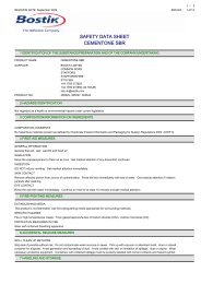
Bevel/Mitre Settings<br />
<br />
on <strong>com</strong>pound mitre saw table<br />
<br />
Fig 43<br />
IL<br />
IR<br />
OL<br />
Note: The chart below references a<br />
<strong>com</strong>pound cut for crown moulding ONLY<br />
WHEN THE ANGLE BETWEEN THE WALLS<br />
EQUALS 90 o .<br />
KEY BEVEL<br />
SETTING<br />
OR<br />
Compound Cut Crown Mouldings<br />
MITRE<br />
SETTING<br />
IL 33.9 0 31.6 0 Right<br />
IR 33.9 0 31.6 0 Left<br />
OL 33.9 0 31.6 0 Left<br />
<br />
OR 33.9 0 31.6 0 Right<br />
TYPE OF CUT<br />
Inside Corner-Left side<br />
1)Position top of moulding against fence<br />
2)Mitre table set at Right 31.6 0<br />
3)Left side is finished piece<br />
Inside Corner-Right side<br />
1)Position bottom of moulding against<br />
fence.<br />
2)Mitre table set LEFT 31.6 0<br />
Outside Corner-Left side<br />
1)Position bottom of moulding against<br />
fence.<br />
2)Mitre table set at Left 31.6 0<br />
3)RIGHT side is finished piece.<br />
Outside Corner-Right side<br />
1)Position top of moulding against fence.<br />
2)Mitre table set at RIGHT 31.6 0<br />
3)RIGHT side is finished piece.<br />
ERBAUER 210MM (8-1/4”) SLIDING COMPOUND MITRE SAW
Fig 44<br />
2<br />
1<br />
MAINTENANCE<br />
Danger: To avoid injury, never put<br />
lubricants on the blade while it<br />
is spinning.<br />
Warning: To avoid fire or toxic<br />
reaction, never use petrol, naphtha,<br />
acetone, lacquer thinner or similar highly<br />
volatile solvents to clean the mitre saw.<br />
Warning: For your safety, this saw<br />
is double-insulated. To avoid electrical<br />
shock, fire or injury, use only parts identical to<br />
those identified in the parts list. Reassemble<br />
exactly as the original assembly to avoid<br />
electrical shock.<br />
Replacing carbon brushes<br />
Replace both carbon brushes when either has<br />
less than 6 mm length of carbon remaining,<br />
or if the spring or wire is damaged or burned.<br />
To inspect or replace brushes, first unplug<br />
the saw. Then remove the black plastic cap<br />
(1) on the side of the motor (2). Remove the<br />
cap cautiously, because it is spring loaded.<br />
Then pull out the brush and replace. Replace<br />
for the other side. To reassemble reverse the<br />
procedure. The ears on the metal end of the<br />
assembly go in the same hole the carbon part<br />
fits into. Tighten the cap snugly, but do not<br />
overtighten. (See fig. 45)<br />
Note: To reinstall the same brushes, first make<br />
sure the brushes go back in the way they<br />
came out. This will avoid serviceable brushes<br />
undergoing a second ‘bedding in’ process that<br />
could reduce motor performance and increases<br />
wear.<br />
Lower blade guard<br />
Do not use the saw without the lower blade<br />
guard. The lower blade guard is attached to the<br />
saw for your protection. Should the lower guard<br />
be<strong>com</strong>e damaged, do not use the saw until the<br />
damaged guard has been replaced. Develop a<br />
regular check to make sure the lower guard is<br />
working properly. Clean the lower guard of any<br />
dust or buildup with a damp cloth.<br />
ERBAUER 210MM (8-1/4”) SLIDING COMPOUND MITRE SAW
Warning: Do not use solvents on the<br />
guard. They could make the plastic<br />
“cloudy” and brittle.<br />
Warning: When cleaning the lower<br />
guard, unplug the saw from the power<br />
source to avoid unexpected startup.<br />
Sawdust<br />
Periodically, sawdust will accumulate under the work<br />
table and base. This could cause difficulty in the<br />
movement of the worktable when setting up a mitre<br />
cut. Frequently blow out or vacuum up the sawdust.<br />
Warning: If blowing sawdust, wear<br />
proper eye protection to keep debris from<br />
blowing into eyes.<br />
Lubrication<br />
All the motor bearings in this tool are lubricated with<br />
a sufficient amount of high grade lubricant for the<br />
life of the unit under normal operating conditions;<br />
therefore, no further bearing lubrication is required.<br />
Lubricate the following as necessary: Chop<br />
pivot: Apply light machine oil to points indicated<br />
in illustration. Central pivot of plastic guard: Use<br />
light household oil (sewing machine oil ) on metalto-metal<br />
or metal-to-plastic guard contact areas<br />
as required for smooth, quiet operation. Avoid<br />
excessive oil, to which sawdust will cling. Guard<br />
arm: (which actuates the lower guard movement)<br />
may be oiled at the rear pivot, greased at ball<br />
bearing contact, and oiled where the guard arm<br />
actuates the acetyl roller of the lower guard, if the<br />
down chop motion is hard.<br />
ERBAUER 210MM (8-1/4”) SLIDING COMPOUND MITRE SAW
ENVIRONMENTAL PROTECTION<br />
Waste electrical products should not be<br />
disposed of with household waste. Please<br />
recycle where facilities exist. Check with your<br />
Local Authority or retailer for recycling advice.<br />
UK PLUG REPLACEMENT<br />
The fuse in the main plug of your power tool should<br />
always be replaced with one of identical rating.<br />
Check the voltage given on your power tool matches<br />
the supply voltage.<br />
The power tool is supplied with a fitted plug, however<br />
if you should need to fit a new plug follows the<br />
instruction below.<br />
IMPORTANT<br />
The wire in the mains lead are coloured in<br />
accordance with the following code:<br />
Blue ---Neutral<br />
Brown ---Live<br />
The wire that is coloured blue must be connected<br />
to the terminal that is marked with the letter N. The<br />
wire that is coloured brown must be connected to<br />
the terminal that is marked with the letter L. A 13AMP<br />
(BS1363 or BS1363/A) plug must be used and a 5<br />
AMP fuse must be fitted.<br />
A 13AMP (BS1363 or BS1363/A) plug must be used<br />
and a 5 AMP fuse must be fitted.<br />
ERBAUER 210MM (8-1/4”) SLIDING COMPOUND MITRE SAW
Declaration of Conformity<br />
We, Importer<br />
Erbauer (UK) Ltd.<br />
BA22 8RT<br />
Declare that the product:<br />
Complies with the essential health and safety<br />
requirements of the following directives:<br />
2004/108/EC – EMC Directive<br />
2006/95/EC – Low Voltage Directive<br />
2006/42/EC – Machinery Directive<br />
2002/95/EC – Restrictions of the Use of Certain Hazardous<br />
Substances in electrical and electronic equipment<br />
2002/96/EC and 2003/108/EC Waste Electrical and Electronic Equipment (WEEE)<br />
Standards and technical specifications referred to:<br />
EN55014-1:2000<br />
EN55014-2:1997+A1<br />
EN61000-3-2:2000<br />
EN61000-3-3:1995+A1+A2<br />
EN61029:2009<br />
EN61029-2-9:2009<br />
EN60825-1:1994+A11+A2<br />
Authorised Signatory<br />
Date: 25/06/2010<br />
Signature:<br />
Name: Peter Harries<br />
Erbauer (UK) Ltd<br />
Quality Manager<br />
2010<br />
ERBAUER 210MM (8-1/4”) SLIDING COMPOUND MITRE SAW
ERBAUER 210MM (8-1/4”) SLIDING COMPOUND MITRE SAW