- Page 2 and 3: © MOTOROLA INC., 1992 MOTOROLA M68
- Page 4 and 5: Paragraph Number iv TABLE OF CONTEN
- Page 6 and 7: Paragraph Number vi TABLE OF CONTEN
- Page 8 and 9: Figure Number MOTOROLA LIST OF FIGU
- Page 10 and 11: Table Number MOTOROLA LIST OF TABLE
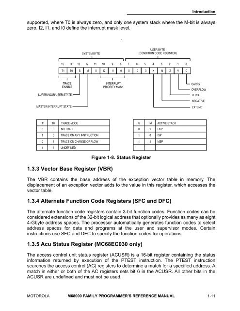
- Page 12 and 13: SECTION 1 INTRODUCTION This manual
- Page 14 and 15: 1.1.3 Program Counter MOTOROLA M680
- Page 16 and 17: 1.2.2 Floating-Point Control Regist
- Page 18 and 19: MOTOROLA M68000 FAMILY PROGRAMMER
- Page 20 and 21: Registers MOTOROLA 68000 68008 68HC
- Page 24 and 25: E—Enable 0 = Transparent translat
- Page 26 and 27: 1.5 FLOATING-POINT DATA FORMATS MOT
- Page 28 and 29: MOTOROLA M68000 FAMILY PROGRAMMER
- Page 30 and 31: 1.6.3 Zeros Introduction Zeros can
- Page 32 and 33: Table 1-4. Single-Precision Real Fo
- Page 34 and 35: Table 1-6. Extended-Precision Real
- Page 36 and 37: 1.7 ORGANIZATION OF DATA IN REGISTE
- Page 38 and 39: Introduction Control registers vary
- Page 40 and 41: BYTE n - 1 7 0 7 0 7 0 BYTE n - 1 A
- Page 42 and 43: SECTION 2 ADDRESSING CAPABILITIES M
- Page 44 and 45: MOTOROLA Table 2-1. Instruction Wor
- Page 46 and 47: 2.2.1 Data Register Direct Mode MOT
- Page 48 and 49: 2.2.5 Address Register Indirect wit
- Page 50 and 51: MOTOROLA M68000 FAMILY PROGRAMMER
- Page 52 and 53: 2.2.9 Memory Indirect Postindexed M
- Page 54 and 55: 2.2.11 Program Counter Indirect wit
- Page 56 and 57: MOTOROLA M68000 FAMILY PROGRAMMER
- Page 58 and 59: 2.2.15 Program Counter Memory Indir
- Page 60 and 61: 2.2.18 Immediate Data MOTOROLA M680
- Page 62 and 63: 2.4 BRIEF EXTENSION WORD FORMAT COM
- Page 64 and 65: A6 = 0 1 2 3 A6 = 0 A6 = 0 1 SIMPLE
- Page 66 and 67: 2.5.2 Memory Indirect Modes Address
- Page 68 and 69: . Addressing Capabilities 2.5.2.3 M
- Page 70 and 71: Addressing Capabilities To implemen
- Page 72 and 73:
SECTION 3 INSTRUCTION SET SUMMARY T
- Page 74 and 75:
MOTOROLA Table 3-1. Notational Conv
- Page 76 and 77:
3.1.1 Data Movement Instructions MO
- Page 78 and 79:
MOTOROLA M68000 FAMILY PROGRAMMER
- Page 80 and 81:
Table 3-5. Shift and Rotate Operati
- Page 82 and 83:
3.1.7 Binary-Coded Decimal Instruct
- Page 84 and 85:
Table 3-10. System Control Operatio
- Page 86 and 87:
3.1.12 Memory Management Unit (MMU)
- Page 88 and 89:
Table 3-17. Monadic Floating-Point
- Page 90 and 91:
LSR (r = 0) — * * 0 0 ROXL (r = 0
- Page 92 and 93:
Instruction Set Summary extends the
- Page 94 and 95:
3.5 FLOATING-POINT COMPUTATIONAL AC
- Page 96 and 97:
3.5.2 Rounding the Result Instructi
- Page 98 and 99:
Instruction Set Summary intermediat
- Page 100 and 101:
Table 3-22. FPCC Encodings Data Typ
- Page 102 and 103:
Table 3-23. Floating-Point Conditio
- Page 104 and 105:
INSTRUCTION NAME APPLICABLE PROCESS
- Page 106 and 107:
Integer Instructions ABCD Operation
- Page 108 and 109:
Integer Instructions ADD Operation:
- Page 110 and 111:
Integer Instructions ADD 4-6 Add (M
- Page 112 and 113:
Integer Instructions ADDA 4-8 Add A
- Page 114 and 115:
Integer Instructions ADDI Add Immed
- Page 116 and 117:
Integer Instructions ADDQ Add Quick
- Page 118 and 119:
Integer Instructions ADDX Add Exten
- Page 120 and 121:
Integer Instructions AND AND Logica
- Page 122 and 123:
Integer Instructions ANDI AND Immed
- Page 124 and 125:
Integer Instructions ANDI ANDI to C
- Page 126 and 127:
Integer Instructions ASL, ASR Arith
- Page 128 and 129:
Integer Instructions ASL, ASR Arith
- Page 130 and 131:
Integer Instructions Bcc Branch Con
- Page 132 and 133:
Integer Instructions BCHG Test a Bi
- Page 134 and 135:
Integer Instructions BCLR Test a Bi
- Page 136 and 137:
Integer Instructions BCLR Test a Bi
- Page 138 and 139:
Integer Instructions BFCHG Test Bit
- Page 140 and 141:
Integer Instructions BFCLR Test Bit
- Page 142 and 143:
Integer Instructions BFEXTS Extract
- Page 144 and 145:
Integer Instructions BFEXTU Extract
- Page 146 and 147:
Integer Instructions BFEXTU Extract
- Page 148 and 149:
Integer Instructions BFFFO Find Fir
- Page 150 and 151:
Integer Instructions BFINS Insert B
- Page 152 and 153:
Integer Instructions BFINS Insert B
- Page 154 and 155:
Integer Instructions BFSET Test Bit
- Page 156 and 157:
Integer Instructions BFTST Test Bit
- Page 158 and 159:
Integer Instructions BKPT Breakpoin
- Page 160 and 161:
Integer Instructions BSET Test a Bi
- Page 162 and 163:
Integer Instructions BSET Test a Bi
- Page 164 and 165:
Integer Instructions BSR Branch to
- Page 166 and 167:
Integer Instructions BTST Test a Bi
- Page 168 and 169:
Integer Instructions CALLM Call Mod
- Page 170 and 171:
Integer Instructions CAS CAS CAS2 C
- Page 172 and 173:
Integer Instructions CAS CAS CAS2 C
- Page 174 and 175:
Integer Instructions CHK Check Regi
- Page 176 and 177:
Integer Instructions CHK2 Check Reg
- Page 178 and 179:
Integer Instructions CLR Clear an O
- Page 180 and 181:
Integer Instructions CMP Compare CM
- Page 182 and 183:
Integer Instructions CMPA Compare A
- Page 184 and 185:
Integer Instructions CMPI Compare I
- Page 186 and 187:
Integer Instructions CMP2 Compare R
- Page 188 and 189:
Integer Instructions cpBcc Branch o
- Page 190 and 191:
Integer Instructions cpGEN Coproces
- Page 192 and 193:
Integer Instructions cpScc Set on C
- Page 194 and 195:
Integer Instructions DBcc Test Cond
- Page 196 and 197:
Integer Instructions DIVS, DIVSL Si
- Page 198 and 199:
Integer Instructions DIVS, DIVSL Si
- Page 200 and 201:
Integer Instructions DIVU, DIVUL Un
- Page 202 and 203:
Integer Instructions DIVU, DIVUL Un
- Page 204 and 205:
Integer Instructions EOR Exclusive-
- Page 206 and 207:
Integer Instructions EORI Exclusive
- Page 208 and 209:
Integer Instructions EORI EORI to C
- Page 210 and 211:
Integer Instructions EXT, EXTB Sign
- Page 212 and 213:
Integer Instructions JMP Jump JMP (
- Page 214 and 215:
Integer Instructions LEA Load Effec
- Page 216 and 217:
Integer Instructions LINK Link and
- Page 218 and 219:
Integer Instructions LSL, LSR Logic
- Page 220 and 221:
Integer Instructions MOVE Move Data
- Page 222 and 223:
Integer Instructions MOVE Move Data
- Page 224 and 225:
Integer Instructions MOVEA Move Add
- Page 226 and 227:
Integer Instructions MOVE MOVE from
- Page 228 and 229:
Integer Instructions MOVE MOVE to C
- Page 230 and 231:
Integer Instructions MOVE16 Move 16
- Page 232 and 233:
Integer Instructions MOVEM Move Mul
- Page 234 and 235:
Integer Instructions MOVEM Move Mul
- Page 236 and 237:
Integer Instructions MOVEP Move Per
- Page 238 and 239:
Integer Instructions MOVEQ Move Qui
- Page 240 and 241:
Integer Instructions MULS Signed Mu
- Page 242 and 243:
Integer Instructions MULU Unsigned
- Page 244 and 245:
Integer Instructions MULU Unsigned
- Page 246 and 247:
Integer Instructions NBCD Negate De
- Page 248 and 249:
Integer Instructions NEG Negate NEG
- Page 250 and 251:
Integer Instructions NEGX Negate wi
- Page 252 and 253:
Integer Instructions NOT Logical Co
- Page 254 and 255:
Integer Instructions OR Inclusive-O
- Page 256 and 257:
Integer Instructions OR Inclusive-O
- Page 258 and 259:
Integer Instructions ORI Inclusive-
- Page 260 and 261:
Integer Instructions PACK Pack PACK
- Page 262 and 263:
Integer Instructions PACK Pack PACK
- Page 264 and 265:
Integer Instructions ROL, ROR Rotat
- Page 266 and 267:
Integer Instructions ROL, ROR Rotat
- Page 268 and 269:
Integer Instructions ROXL, ROXR Rot
- Page 270 and 271:
Integer Instructions RTD Return and
- Page 272 and 273:
Integer Instructions RTR Return and
- Page 274 and 275:
Integer Instructions SBCD Subtract
- Page 276 and 277:
Integer Instructions Scc Set Accord
- Page 278 and 279:
Integer Instructions SUB Subtract S
- Page 280 and 281:
Integer Instructions SUB Subtract S
- Page 282 and 283:
Integer Instructions SUBA Subtract
- Page 284 and 285:
Integer Instructions SUBI Subtract
- Page 286 and 287:
Integer Instructions SUBQ Subtract
- Page 288 and 289:
Integer Instructions SUBX Subtract
- Page 290 and 291:
Integer Instructions TAS Test and S
- Page 292 and 293:
Integer Instructions TRAP Trap TRAP
- Page 294 and 295:
Integer Instructions TRAPcc Trap on
- Page 296 and 297:
Integer Instructions TST Test an Op
- Page 298 and 299:
Integer Instructions UNLK Unlink UN
- Page 300 and 301:
Integer Instructions UNPK Unpack BC
- Page 302 and 303:
Integer Instructions 4-198 M68000 F
- Page 304 and 305:
Floating Point Instructions 5-2 Tab
- Page 306 and 307:
Floating Point Instructions FABS Op
- Page 308 and 309:
Floating Point Instructions FABS In
- Page 310 and 311:
Floating Point Instructions FACOS O
- Page 312 and 313:
Floating Point Instructions FACOS 5
- Page 314 and 315:
Floating Point Instructions FADD Fl
- Page 316 and 317:
Floating Point Instructions FASIN A
- Page 318 and 319:
Floating Point Instructions FASIN A
- Page 320 and 321:
Floating Point Instructions FATAN A
- Page 322 and 323:
Floating Point Instructions FATANH
- Page 324 and 325:
Floating Point Instructions FATANH
- Page 326 and 327:
Floating Point Instructions FBcc Fl
- Page 328 and 329:
Floating Point Instructions FCMP Fl
- Page 330 and 331:
Floating Point Instructions FCOS Co
- Page 332 and 333:
Floating Point Instructions FCOS Co
- Page 334 and 335:
Floating Point Instructions FCOSH H
- Page 336 and 337:
Floating Point Instructions FDBcc F
- Page 338 and 339:
Floating Point Instructions FDIV Fl
- Page 340 and 341:
Floating Point Instructions FDIV Fl
- Page 342 and 343:
Floating Point Instructions FETOX e
- Page 344 and 345:
Floating Point Instructions FETOX e
- Page 346 and 347:
Floating Point Instructions FETOXM1
- Page 348 and 349:
Floating Point Instructions FGETEXP
- Page 350 and 351:
Floating Point Instructions FGETEXP
- Page 352 and 353:
Floating Point Instructions FGETMAN
- Page 354 and 355:
Floating Point Instructions FINT In
- Page 356 and 357:
Floating Point Instructions FINT In
- Page 358 and 359:
Floating Point Instructions FINTRZ
- Page 360 and 361:
Floating Point Instructions FLOG10
- Page 362 and 363:
Floating Point Instructions FLOG10
- Page 364 and 365:
Floating Point Instructions FLOG2 L
- Page 366 and 367:
Floating Point Instructions FLOGN L
- Page 368 and 369:
Floating Point Instructions FLOGN L
- Page 370 and 371:
Floating Point Instructions FLOGNP1
- Page 372 and 373:
Floating Point Instructions FMOD Mo
- Page 374 and 375:
Floating Point Instructions FMOD Mo
- Page 376 and 377:
Floating Point Instructions FMOVE M
- Page 378 and 379:
Floating Point Instructions FMOVE M
- Page 380 and 381:
Floating Point Instructions FMOVE M
- Page 382 and 383:
Floating Point Instructions FMOVE M
- Page 384 and 385:
Floating Point Instructions FMOVE M
- Page 386 and 387:
Floating Point Instructions FMOVECR
- Page 388 and 389:
Floating Point Instructions FMOVEM
- Page 390 and 391:
Floating Point Instructions FMOVEM
- Page 392 and 393:
Floating Point Instructions FMOVEM
- Page 394 and 395:
Floating Point Instructions FMOVEM
- Page 396 and 397:
Floating Point Instructions FMUL Fl
- Page 398 and 399:
Floating Point Instructions FMUL Fl
- Page 400 and 401:
Floating Point Instructions FNEG Fl
- Page 402 and 403:
Floating Point Instructions FNEG Fl
- Page 404 and 405:
Floating Point Instructions FNOP No
- Page 406 and 407:
Floating Point Instructions FREM IE
- Page 408 and 409:
Floating Point Instructions FREM IE
- Page 410 and 411:
Floating Point Instructions FSCALE
- Page 412 and 413:
Floating Point Instructions FScc Se
- Page 414 and 415:
Floating Point Instructions FSGLDIV
- Page 416 and 417:
Floating Point Instructions FSGLDIV
- Page 418 and 419:
Floating Point Instructions FSGLMUL
- Page 420 and 421:
Floating Point Instructions FSIN Si
- Page 422 and 423:
Floating Point Instructions FSIN Si
- Page 424 and 425:
Floating Point Instructions FSINCOS
- Page 426 and 427:
Floating Point Instructions FSINCOS
- Page 428 and 429:
Floating Point Instructions FSINH H
- Page 430 and 431:
Floating Point Instructions FSQRT F
- Page 432 and 433:
Floating Point Instructions FSQRT F
- Page 434 and 435:
Floating Point Instructions FSUB Fl
- Page 436 and 437:
Floating Point Instructions FSUB Fl
- Page 438 and 439:
Floating Point Instructions FTAN Ta
- Page 440 and 441:
Floating Point Instructions FTAN Ta
- Page 442 and 443:
Floating Point Instructions FTANH H
- Page 444 and 445:
Floating Point Instructions FTENTOX
- Page 446 and 447:
Floating Point Instructions FTENTOX
- Page 448 and 449:
Floating Point Instructions FTRAPcc
- Page 450 and 451:
Floating Point Instructions FTST Te
- Page 452 and 453:
Floating Point Instructions FTWOTOX
- Page 454 and 455:
Floating Point Instructions FTWOTOX
- Page 456 and 457:
Supervisor (Privileged) Instruction
- Page 458 and 459:
Supervisor (Privileged) Instruction
- Page 460 and 461:
Supervisor (Privileged) Instruction
- Page 462 and 463:
Supervisor (Privileged) Instruction
- Page 464 and 465:
Supervisor (Privileged) Instruction
- Page 466 and 467:
Supervisor (Privileged) Instruction
- Page 468 and 469:
Supervisor (Privileged) Instruction
- Page 470 and 471:
Supervisor (Privileged) Instruction
- Page 472 and 473:
Supervisor (Privileged) Instruction
- Page 474 and 475:
Supervisor (Privileged) Instruction
- Page 476 and 477:
Supervisor (Privileged) Instruction
- Page 478 and 479:
Supervisor (Privileged) Instruction
- Page 480 and 481:
Supervisor (Privileged) Instruction
- Page 482 and 483:
Supervisor (Privileged) Instruction
- Page 484 and 485:
Supervisor (Privileged) Instruction
- Page 486 and 487:
Supervisor (Privileged) Instruction
- Page 488 and 489:
Supervisor (Privileged) Instruction
- Page 490 and 491:
Supervisor (Privileged) Instruction
- Page 492 and 493:
Supervisor (Privileged) Instruction
- Page 494 and 495:
Supervisor (Privileged) Instruction
- Page 496 and 497:
Supervisor (Privileged) Instruction
- Page 498 and 499:
Supervisor (Privileged) Instruction
- Page 500 and 501:
Supervisor (Privileged) Instruction
- Page 502 and 503:
Supervisor (Privileged) Instruction
- Page 504 and 505:
Supervisor (Privileged) Instruction
- Page 506 and 507:
Supervisor (Privileged) Instruction
- Page 508 and 509:
Supervisor (Privileged) Instruction
- Page 510 and 511:
Supervisor (Privileged) Instruction
- Page 512 and 513:
Supervisor (Privileged) Instruction
- Page 514 and 515:
Supervisor (Privileged) Instruction
- Page 516 and 517:
Supervisor (Privileged) Instruction
- Page 518 and 519:
Supervisor (Privileged) Instruction
- Page 520 and 521:
Supervisor (Privileged) Instruction
- Page 522 and 523:
Supervisor (Privileged) Instruction
- Page 524 and 525:
Supervisor (Privileged) Instruction
- Page 526 and 527:
Supervisor (Privileged) Instruction
- Page 528 and 529:
Supervisor (Privileged) Instruction
- Page 530 and 531:
Supervisor (Privileged) Instruction
- Page 532 and 533:
Supervisor (Privileged) Instruction
- Page 534 and 535:
Supervisor (Privileged) Instruction
- Page 536 and 537:
Supervisor (Privileged) Instruction
- Page 538 and 539:
Supervisor (Privileged) Instruction
- Page 540 and 541:
Supervisor (Privileged) Instruction
- Page 542 and 543:
CPU32 Instructions Addressing in th
- Page 544 and 545:
CPU32 Instructions BGND Operation:
- Page 546 and 547:
CPU32 Instructions TBLS TBLS TBLSN
- Page 548 and 549:
CPU32 Instructions TBLS TBLS TBLSN
- Page 550 and 551:
CPU32 Instructions TBLS TBLS TBLSN
- Page 552 and 553:
CPU32 Instructions TBLU TBLU TBLUN
- Page 554 and 555:
CPU32 Instructions TBLU TBLU TBLUN
- Page 556 and 557:
CPU32 Instructions 7-16 M68000 FAMI
- Page 558 and 559:
Instruction Format Summary 8.1.5 De
- Page 560 and 561:
Instruction Format Summary 8.1.8 Si
- Page 562 and 563:
Instruction Format Summary SUBI RTM
- Page 564 and 565:
Instruction Format Summary BCLR 8-8
- Page 566 and 567:
Instruction Format Summary MOVE fro
- Page 568 and 569:
Instruction Format Summary ILLEGAL
- Page 570 and 571:
Instruction Format Summary STOP 15
- Page 572 and 573:
Instruction Format Summary DBcc 15
- Page 574 and 575:
Instruction Format Summary SUBX 15
- Page 576 and 577:
Instruction Format Summary ADD ASL,
- Page 578 and 579:
Instruction Format Summary BFINS 15
- Page 580 and 581:
Instruction Format Summary PFLUSH P
- Page 582 and 583:
Instruction Format Summary PFLUSHR
- Page 584 and 585:
Instruction Format Summary MOVE16 A
- Page 586 and 587:
Instruction Format Summary FLOGNP1
- Page 588 and 589:
Instruction Format Summary FLOGN 15
- Page 590 and 591:
Instruction Format Summary FSGLMUL
- Page 592 and 593:
Instruction Format Summary FMOVE DA
- Page 594 and 595:
Instruction Format Summary cpRESTOR
- Page 596 and 597:
Instruction Format Summary 8-40 M68
- Page 598 and 599:
Processor Instruction Summary A-2 T
- Page 600 and 601:
Processor Instruction Summary A-4 T
- Page 602 and 603:
Processor Instruction Summary A-6 T
- Page 604 and 605:
Processor Instruction Summary Table
- Page 606 and 607:
Processor Instruction Summary A-10
- Page 608 and 609:
Processor Instruction Summary A.1 M
- Page 610 and 611:
Processor Instruction Summary Table
- Page 612 and 613:
Processor Instruction Summary A.1.2
- Page 614 and 615:
Processor Instruction Summary Table
- Page 616 and 617:
Processor Instruction Summary A.2.2
- Page 618 and 619:
Processor Instruction Summary Table
- Page 620 and 621:
Processor Instruction Summary A.3.2
- Page 622 and 623:
Processor Instruction Summary Table
- Page 624 and 625:
Processor Instruction Summary Table
- Page 626 and 627:
Processor Instruction Summary A.5 M
- Page 628 and 629:
APPENDIX B EXCEPTION PROCESSING REF
- Page 630 and 631:
B.2 EXCEPTION STACK FRAMES MOTOROLA
- Page 632 and 633:
MOTOROLA SP +$02 +$06 +$08 +$0C 15
- Page 634 and 635:
MOTOROLA SP +$02 +$06 +$08 +$0A +$0
- Page 636 and 637:
MOTOROLA 15 0 SP STATUS REGISTER +$
- Page 638 and 639:
Exception Processing Reference B-11
- Page 640 and 641:
B-13 MC68000 FAMILY PROGRAMMER’S
- Page 642 and 643:
S-Record Output Format When downloa
- Page 644 and 645:
S-Record Output Format The next 16