
Create successful ePaper yourself
Turn your PDF publications into a flip-book with our unique Google optimized e-Paper software.
Page 14<br />
EEPROM. A high-power bus powered device must use this descriptor in the internal EEPROM to inform the<br />
system of its power requirements.<br />
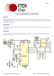
v) For 3.3V power controlled circuits the VCCIO pin must not be powered down with the external circuitry (the<br />
PWREN# signal gets its VCC supply from VCCIO). Either connect the power switch between the output of the<br />
3.3V regulator and the external 3.3V logic or power VCCIO from the 3V3OUT pin of the FT232R.<br />
6.4 LED Interface<br />
The FT232RL’s CBUS0 and CBUS1 pins on the <strong>EVAL232R</strong> are configured to drive LED’s.<br />
CBUS0 is used to indicate reception of data (RXLED#) and CBUS1 is used to indicate transmission of data (TXLED#).<br />
When data is being transmitted or received the respective CBUS pin will drive from tri-state to low in order to provide<br />
indication on the LEDs of data transfer. A digital one-shot time is used so that even a small percentage of data transfer<br />
is visible to the end user.<br />
The FT232R CBUS pins have 3 configurable options for driving an LED - these are TXLED#, RXLED#, and<br />
TX&RXLED#.<br />
<strong>EVAL232R</strong> FT232RL USB to RS232 Evaluation Module <strong>Datasheet</strong> Version 0.90 © Future Technology Devices International Ltd. 2005