IMPORTANT SAFETY INSTRUCTIONS
IMPORTANT SAFETY INSTRUCTIONS
IMPORTANT SAFETY INSTRUCTIONS

Create successful ePaper yourself
Turn your PDF publications into a flip-book with our unique Google optimized e-Paper software.
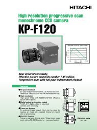
3-CCD Color Camera<br />
MODEL HV-D27<br />
27HV-D<br />
HV-D37<br />
OPERATION MANUAL<br />
Please read this operation manual carefully for proper operation, and keep<br />
it for future reference.<br />
Note:<br />
The model and serial numbers of your product are important for you to keep for your<br />
convenience and protection. These numbers appear on the nameplate located on the bottom of<br />
the product. Please record these numbers in the spaces provided below, and retain this manual<br />
for future reference.<br />
Model No.<br />
Serial No.<br />
Hitachi Denshi, Ltd.
<strong>IMPORTANT</strong> <strong>SAFETY</strong> <strong>INSTRUCTIONS</strong><br />
1. Read Instructions<br />
All the safety and operating instructions should be read before the product is operated.<br />
2. Retain Instructions<br />
The safety and operating instructions should be retained for future reference.<br />
3. Heed Warnings<br />
All warnings on the product and the operating instructions should be adhered to.<br />
4. Follow Instructions<br />
All operating and use instructions should be followed.<br />
5. Cleaning<br />
Unplug this product from the wall outlet before cleaning. Do not use liquid cleaners or aerosol cleaners.<br />
Use a damp cloth for cleaning.<br />
6. Attachments<br />
Do not use attachments not recommended by the product manufacturer as they may cause hazards.<br />
7. Water and Moisture<br />
Do not use this product near water - for example, near a bath tub, wash bowl, kitchen sink, or laundry tub; in<br />
a wet basement; or near a swimming pool; and the like.<br />
8. Accessories<br />
Do not place this product on an unstable cart, stand, tripod, bracket, or table. The product may fall, causing<br />
serious injury to a child or adult, and serious damage to the product. Use only with a cart, stand, tripod,<br />
bracket, or table recommended by the manufacturer, or sold with the product. Any mounting of the product<br />
should follow the manufacturer's instructions, and should use a mounting accessory recommended by the<br />
manufacturer.<br />
9. Moving<br />
A product and cart combination should be moved with care.<br />
Quick stops, excessive force, and uneven surfaces may cause the product and cart combination to overturn.<br />
10. Ventilation<br />
Slots and openings in the cabinet are provided for ventilation and to ensure reliable operation of the product<br />
and to protect it from overheating, and these openings must not be blocked or covered.<br />
The openings should never be blocked by placing the product on a bed, sofa, rug, or other similar surface.<br />
This product should not be placed in a built-in installation such as a bookcase or rack unless proper<br />
ventilation is provided or the manufacturer's instructions have been adhered to.<br />
11. Power Sources<br />
This product should be operated only from the type of power source indicated on the marking label. If you<br />
are not sure of the type of power supply to your home, consult your product dealer or local power company.<br />
For products intended to operate from battery power, or other sources, refer to the operating instructions.<br />
A
12. Grounding or Polarization<br />
This product is equipped with a three-wire grounding-type plug a plug having a third (grounding) pin. This<br />
plug will only fit into a grounding-type power outlet. This is a safety feature. If you are unable to insert<br />
the plug into the outlet, contact your electrician to replace your obsolete outlet. Do not defeat the safety<br />
purpose of the grounding-type plug.<br />
13. Power-Cord Protection<br />
Power-supply cords should be routed to that they are not likely to be walked on or pinched by items placed<br />
upon or against them, paying particular attention to cords at plug, convenience receptacles, and the point<br />
where they exit from the product.<br />
14. Lightning<br />
For added protection for this product during a lightning storm, or when it is left unattended and unused for<br />
long periods of time, unplug it from the wall outlet. This will prevent damage to the product due to<br />
lightning and power-line surges.<br />
15. Overloading<br />
Do not overload wall outlets, extension cords or integral convenience receptacles as this can result in a risk<br />
of fire or electric shock.<br />
16. Object and Liquid Entry<br />
Never push objects of any kind into this product through openings as they may touch dangerous voltage<br />
points or short-out parts that could result in a fire or electric shock. Never spill liquid of any kind on the<br />
product.<br />
17. Inflammable and Explosive Substance<br />
Avoid using this product where there are gases, and also where there are inflammable and explosive<br />
substances in the immediate vicinity.<br />
18. Heavy Shock or Vibration<br />
When carrying this product around, do not subject the product to heavy shock or vibration.<br />
19. Servicing<br />
Do not attempt to service this product yourself as opening or removing covers may expose you to dangerous<br />
voltage or other hazards. Refer all servicing to qualified service personnel.<br />
20. Damage Requiring Service<br />
Unplug this product from the wall outlet and refer servicing to qualified service personnel under the<br />
following conditions:<br />
a. When the power-supply cord or plug is damaged.<br />
b. if liquid has been spilled, or objects have fallen into the product.<br />
c. If the product has been exposed to rain or water.<br />
d. If the product does not operate normally by following the operating instructions. Adjust only those<br />
controls that are covered by the operating instructions as an improper adjustment of other controls may<br />
result in damage and will often require extensive work by a qualified technician to restore the product to<br />
its normal operation.<br />
e. If the product has been dropped or damaged in any way.<br />
f. When the product exhibits a distinct change in performance-this indicates a need for service.<br />
B
21. Replacement Parts<br />
When replacement parts are required, be sure the service technician has used replacement parts specified by<br />
the manufacturer or have the same characteristics as the original part.<br />
Unauthorized substitutions may result in fire, electric shock, or other hazards.<br />
22. Safety Check<br />
Upon completion of any service or repairs to this product, ask the service technician to perform safety checks<br />
to determine that the product is in proper operating condition.<br />
23. Wall or Ceiling Mounting<br />
The product should be mounted to a wall or ceiling only as recommended by the manufacturer.<br />
24. Heat<br />
The product should be situated away from heat sources such as radiators, heat registers, stoves, or other<br />
products (including amplifiers) that produce heat.<br />
C
WICHTIGE SICHERHEITSANWEISUNGEN<br />
1. Alle Anweisungen lesen.<br />
Vor Betrieb des Erzeugnisses sollten alle Sicherheits-und Bedienungsanleitungen gelesen werden.<br />
2. Die Anweisungen aufbewahren.<br />
Die Sicherheits-und Bedienungsanleitungen sollten fünftigen Bezug aufbewahrt werden.<br />
3. Warnungen beachten.<br />
Die Warnungen auf dem Erzeugnis und in den Bedienungsanleitungen solten beachtet werden.<br />
4. Anweisungen befolgen.<br />
Alle Bedienungsanleitung-und<br />
Verwendungsanweisungen sollten befolgt werden.<br />
5. Reinigung<br />
Den Stecker des Geräts vor Reinigung aus der Steckdose ziehen. Keine flüssigen Reinigungsmittel oder<br />
Aerosolreiniger verwenden. Zum Reinigen einen feuchten Lappen verwenden.<br />
6. Zubehör<br />
Nur vom-Hersteller des Erzeugnisses empfohlenes Zubehör verwenden, da es sonst zu Störungen kommen<br />
kann.<br />
7. Wasser und Feuchtigkeit<br />
Dieses Erzeugnis nicht in der Nähe von Wasser verwenden - z.B, in der Nähe einer Badewanne, eines<br />
Waschbeckens, einer Küchenspüle, eines Waschzubers, in einem nassen Keller, in der Nähe eines<br />
Schwimmbeckens usw.<br />
8. Aufstellung<br />
Das Erzeugnis nicht auf einen unstabilen Wagen, Stand, Dreifuß, Träger oder Tisch stellen.<br />
Das Erzeugnis kann sonst herunterfallen und ein kind oder einen Erwachsenen schwer verietzen.<br />
Außerdem kann das Gerät schwer beschädigt werden. Nur mit einem Wagen, Stand, Dreifuß, Träger oder<br />
Tisch verwenden, der vom Hersteller empfohlen oder mit dem Erzeugnis verkauft worden ist. Für jegliche<br />
Anbringung sollten die Anweisungen des Herstellers befolgt werden, und das vom Hersteller empfohlene<br />
Anbringungszubehör sollte verwendet werden.<br />
9. Eine Kombination von Erzeugnis und Wagen sollte vorsichtig bewegt werden.<br />
Schneller Halt, übermäßige Krafteinwirkung und unebene Oberflächen können Umkippen der kombination<br />
von Erzeugnis und Wagen verursachen.<br />
10. Ventilation<br />
Schlitze und Öffnungen im Gehäuse dienen der Ventilation. Sie sind für zuverlässigen Betrieb des Gerätes<br />
und Schutz vor Überhitzung erforderlich und dürfen nicht blockiert oder abgedeckt werden.<br />
Die Öffnungen sollten niemals dadurch blockiert werden, daß, das Gerät auf ein Bett, ein Sofa, einen Teppich<br />
oder eine ähnliche Oberfläche gestellt wird.<br />
Das Gerät sollte nur dann in Einbauinstallierung wie in einem Bücherschrank oder einem Gestell verwendet<br />
werden, wenn angemessene Ventilation vorgesehen ist bzw. Die Anweisungen des Herstellers befolgt<br />
worden sind.<br />
D
11. Stromversorgung<br />
Dieses Erzeugnis sollte nur an der auf dem Typenschild angegebenen Stromversorgungsart betrieben<br />
werden. Wenn Sie nicht sicher sind, was für eine Stromversorgung Sie haben, so wenden Sie sich bitte an<br />
Ihren Erzeugnishändler oder an das lokale Elektrizitätswerk. Beziehen Sie sich für Batteriebetrieb oder<br />
andere Stromquellen vorgesehene Erzeugnisse bitte auf die Bedienungsanleitungen.<br />
12. Erdung oder Polarisierung<br />
Dieses Erzeugnis ist mit einem Schutzkontaktstecker mit drei Leitern ausgerüstet, mit einem<br />
Erdungskontakt. Dieser Stecker paßt nur in ein schuko-Steckdose. Dies ist eine Sicherheitsmaßnahme.<br />
Wenn Sie den Stecker nicht in die Steckdose stecken können, so wenden Sie sich bitte an ihren Elektriker,<br />
damit er die veraltete Schuts des Schutzkontaktsteckers unwirksam.<br />
13. Netzkabelschutz<br />
Netzkabel sollten so verlegt werden, deß möglichst nicht darauf getreten wird und daß sie nicht eingeklemmt<br />
werden, mit besonderer Beachtung der kabel an Stackern, Verlängerungskabeln und dem Austritt des<br />
Kabels aus dem Erzeugnis.<br />
14. Blitzschlag<br />
Für zusätzlichen Schutz des Erzeugnisses während eines Gewitters oder bei Nichtverwendung für lange Zeit<br />
den Stecker aus der Steckdose ziehen. Dies verhütet Beschädigung durch Blitzschlag und<br />
Netzspannungsstöße.<br />
15. Überlastung<br />
Wandsteckdosen, Verlängerungskabel und eingebaute Bequemlickkeitssteckdosen nicht überlasten, da dies<br />
Feuer oder elektrischen Schlag verursachen kann.<br />
16. Eindringen von Fremdkörpern rpern und Flüssigkeit<br />
Niemals Objekte irgendwelcher Art durch die Öffnungen in das Gerät schieben, da diese unter hoher<br />
Spannung stehende Teile berühren oder kurzschließen können, wodurch es zu Feuer oder elektrischem<br />
Schlag kommen kann. Niemals Flüssigkeiten irgendwelcher Art auf das Erzeugnis verschütten.<br />
17. Entflammbare und explosive Substanzen<br />
Vermeiden Sie Verwendung dieses Erzeugnisses an Orten mit Gasen bzw. entflammbaren oder explosiven<br />
Substanzen in der direkten Umgebung.<br />
18. Starke stöße oder Vibrationen<br />
Setzen Sie das Erzeugnis beim Transport nicht starken Stößen oder Vibrationen aus.<br />
19. Wartung<br />
Versuchen Sie nicht, dieses Erzeugnis Selbst zu warten, da Sie sich durch Öffnen bzw. Entfernen von<br />
Abdeckungen hohen Spannungen und sonstigen Gefährdungen ausserzen können.<br />
Beziehen Sie sich für jegliche Wartung auf qualifiziertes Wartungspersonal.<br />
E
20. Beschädigung, die Wartung erfordert<br />
Ziehen Sie den Stecker dieses Erzeugnisses aus der Steckdose und wenden Sie sich an qualifiziertes<br />
Wartungspersonal, wenn eine der folgenden Bedingungen vorliegt:<br />
a. Wenn das Netzkabel oder der Stecker beschädigt ist.<br />
b. Bei Eindringen von Flüssigkeit oder Fremdkörpern in das Gerät.<br />
c. Wenn das Erzeugnis Regen oder Wasser ausgesetzt worden ist.<br />
d. Wenn das Erzeugnis bei Befolgen der Bedienungsanleitungen nicht normal funktioniert.<br />
Nur die Regelelemente verstellen, die in den Bedienungsanleitungen behandelt werden, da<br />
unangemessene Einstellung anderer Regelelemente Beschädigung verursachen kann und oft beträchtliche<br />
Arbeit durch einen qualifizierten Techniker erfordert, um das Erzeugnis wieder, zu normalem Betrieb<br />
zurückzubringen.<br />
e. Wenn das Erzeugnis fallen gelassen oder beschädigt worden ist.<br />
f. Wenn das Erzeugnis eine klare Änderung in der Leistung zeigt-dies weist darauf hin, daß Wartung<br />
erforderlich ist.<br />
21. Ersatzteile<br />
Wenn Ersatzteile erforderlich sind, darauf achten, daß der Wartungstechniker nur die vom Hersteller<br />
festgelegten Ersatzteile oder Teile mit den gleichen Charakteristiken wie die ursprünglichen Teile<br />
verwendet. Unautorisierte Ersatzteile können Feuer, elektrischen Schlag oder sonstige Gefährdungen<br />
verursachen.<br />
22. Sicherheitsprüfung<br />
Bitten Sie den Wartungstechniker nach der Vollendung von Wartung oder Reparaturarbeiten an diesem<br />
Erzeugnis um die Durchführung von Sicherheitsprüfungen, um zu bestimmen, daß das Erzeugnis im<br />
angemissenen Betriebszustand ist.<br />
23. Anbringung an der Wand oder an der Decke<br />
Das Erzeugnis sollte nur entsprechend den Empfehlungen des Herstellers an einer Wand oder an der Decke<br />
angebracht werden.<br />
24. Wärme<br />
Das Erzeugnis sollte fern von Wärmequellen wie Radiatoren, Heizwiderständen, Öfen und anderen Wärme<br />
erzeugenden Erzeugnissen (einschließlich Verstärkern) aufgestellt werden.<br />
F
MISES EN GARDE <strong>IMPORTANT</strong>ES<br />
1. Lire les instructions<br />
Lire toutes les instructions de sécurité et de fonctionnement avant de faire fonctionner l’appareil.<br />
2. Conserver ces instructions<br />
Conserver les instructions de sécurité et de fonctionnement á des fins de référence ultérieure.<br />
3. Tenir compte des avertissements<br />
Tous les avertissements qui figurent sur l’appareil et dans le mode d’emploi devront être respectés.<br />
4. Observer les instructions<br />
Observer toutes les instructions de fonctionnement et d’utilisation.<br />
5. Nettoyage<br />
Avant de procéder au nettoyage, débrancher l’appareil de la prise secteur. Ne pas utiliser de produits de<br />
nettoyage liquides ou en aérosol.<br />
Nettoyer l’appareil avec un chiffon humide.<br />
6. Fixations<br />
Ne pas utiliser de fixations non recommandées par le fabricant de l’appareil car elles pourraient être source<br />
de danger.<br />
7. Eau et humidité<br />
Ne pas utiliser l’appareil á proximité d’eau-par exemple prés d’une baignoire, d’un lavabo, d’un évier ou d’un<br />
bac á lessive, dans un sous-sol humide, ou prés d’une piscine, etc.<br />
8. Accessoires<br />
Ne pas placer l’appareil sur un chariot, un socle, un pied, un support ou one table instables L’appareil<br />
pourrait tomber, blessant griévement des enfants ou des adultes, et étant sérieusement endommagé.<br />
Utiliser exclusivement le chariot, le socle, le pied, le support ou la table recommandés par le fabricant, ou<br />
vendus avec l’appareil. Pour tout montage de l’appareil, respecter les instructions du fabricant, et utiliser á<br />
cette fin l’accessoire de montage recommandé par le fabricant.<br />
9. L’appareil L<br />
monté sur son chariot devra être déplac<br />
d<br />
placé avec précaution.<br />
Des arrêts brusques, une force excessive et des surfaces irréguliéres pourraient provoquer le renversement<br />
de l’ensemble appareil-chariot.<br />
10. Ventilation<br />
Les fentes et les ouvertures du coffret sont prévues pour la ventilation ainsi que pour garantir un<br />
fonctionnement en toute sécurité de l’appareil et le protéger de toute surchauffe, et ces ouvertures ne devront<br />
donc être ni obstruées ni recouvertes. Ne jamais obstruer les ouvertures en placant l’appareil sur un lit, un<br />
sofa, un tapis ou toute surface similaire. Ne jamais placer l’appareil dans un support confiné, par exemple<br />
une bibliothéque ou une é tagé re, sans ventilation suffisante ou sans repecter les instructions du fabricant.<br />
11. Sources d’allmentation<br />
d<br />
L’appareil devra être alimenté exclusivement sur le type d’alimentation indiqué sur l’étiquette signalétique.<br />
Sil’on n’est pas sûr du type d’alimentatio du local, consulter le revendeur de l’appareil ou la compagnie<br />
d’électricité locale. Pour les appareils qui fonctionnent sur batterie ou sur d’autres sources, voir le mode<br />
d’emploi.<br />
G
12. Mise á la terre ou polarisation<br />
L’appareil est doté d’une fiche trifilaire avec mise á la terre, dont la troisiéme broche assure la mise á la terre.<br />
Cette fiche ne rentrera que dans les prises trifilaires de mise á la terre. Ceci est une mesure de sécurité. Si<br />
la fiche ne rentre pas dans la prise, faire remplacer la prise désuéte par un électricien.<br />
Ne pas rendre vaine la measure de sécurité assurée par cette prise avec mise á la terre.<br />
13. Protection du cordon d’alimentation<br />
d<br />
Acheminer les cordons d’alimentation de facon qu’on ne risque pas de marcher dessus ou de les coincer sous<br />
un objet placé dessus ou contre eux.<br />
Faire particuliérement attention aux fiches des cordons, á la proximité des prises, et á l’endroit oú ils<br />
ressortent de l’appareil.<br />
14. Foudre<br />
Pour renforcer la protection de l’appareil pendant un orage, ou si l’on s’en éloigne ou qu’on reste longtemps<br />
sans l’utiliser, le débrancher de la source d’alimentation. Ceci permettra d’éviter tout dommage de<br />
l’appareil dú á la foudre et aux surtensions de ligne.<br />
15. Surcharge<br />
Ne pas surcharger les prises, rallonges et prises multiples car cela pourrait entraîner un risque de feu ou de<br />
choc électrique.<br />
16. Pénétration P<br />
d’objets d<br />
et de liquides<br />
Ne jamais enfoncer d’objets d’aucune sorte dans les ouvertures de l’appareil car ils pourraient toucher des<br />
points de tension dangereuse ou court-circuiter des piéces, ce qui pourrait provoquer un feu ou un choc<br />
électrique. Ne jamais renverser de liquide d’aucune sorte sur l’appareil.<br />
17. Substances inflammabes et explosives<br />
Eviter d’utiliser l’appareil en présence de gaz, ainsi qu’á proximité immédiate de substances inflammables et<br />
explosives.<br />
18. Chocs ou vibrations violents<br />
Lorsqu’on transporte l’appareil, ne pas le soumettre á des chocs ou des vibrations violents.<br />
19. Réparations<br />
R<br />
Ne pas tenter de réparer l’aapareil soi-même car le fait d’ouvrir ou de retirer les caches risque d’exposer<br />
l’utilisateur á des tensions dangereuses notamment. Confier toute réparation á un personnel qualifié.<br />
20. Dommages nécessitant n<br />
réparations<br />
r<br />
Débrancher l’appareil de la source d’alimentation et confier les réparations á un personnel qualifié dans les<br />
cas suivants:<br />
a. Lorsque le cordon d’alimentation ou sa fiche sont endommagés<br />
b. Si du liquide s’est renversé sur l’appareil ou que des objets sont tombés dedans<br />
c. Si l’appareil a été exposé á la pluie ou á l’eau.<br />
d. Si l’appareil ne fonctionne pas normalement lorsqu’on observe les instructions d’utilisation.<br />
Ne régler que les commandes couvertes par le mode d’emploi ; en effet, un réglage incorrect des autres<br />
commandes pourrait entrainer des dommages et nécessiteront souvent des travaux de réparation coûteux<br />
par un technicien qualifié pour remettre l’appareil en état de marche.<br />
e. Si l’appareil est tombé ou qu’il a été endommagé.<br />
f. Si l’appareil affiche une nette modification de ses performances, cela signifie qu’il a besoin d’être réparé.<br />
H
21. Piéces de rechange<br />
Si l’on a besoin de piéces de rechange, veiller á ce que le technicien de réparation utilise exclusivement les<br />
piéces de rechange spécifiées par le fabricant ou des piéces ayant les mêmes caractéristiques que les piéces<br />
d’origine. Les piéces de rechange non autorisées risquent de provoquer un feu, un choc électrique et autres<br />
dangers.<br />
22. Vérificaton V<br />
de sécurit<br />
s<br />
curité<br />
Aprés tout travail d’entretien ou de réparation de l’appareil, demander au technicien de réparation<br />
d’effectuer les vérifications de sécurité pour s’assurer que l’appareil est en bon état de marche.<br />
23.Montage au mur ou au plafond<br />
L’appareil ne pourra être monté au mur ou au plafond que de la maniére recommandée par le fabricant.<br />
24. Chaleur<br />
Eloigner l’appareil des sources de chaleur, telles que radiateurs, appareils de chauffage, cuisiniéres, et de<br />
tour produit engendrant de la chaleur (y compris les amplificateurs).<br />
I
<strong>IMPORTANT</strong> NOTICE<br />
For USA<br />
These products have been tested and found to comply with the limits for a Class A digital device, pursuant to<br />
Part 15 of the FCC Rules. These limits are designed to provide reasonable protection against harmful<br />
interference when the equipment is operated in a commercial environment. This equipment generates,<br />
uses, and can radiate radio frequency energy and, if not installed and used in accordance with the<br />
instruction manual, may cause harmful interference to radio communications. Operation of this product in<br />
a residential area is likely to cause harmful interference in which case the user will be required to correct the<br />
interference at his own expense.<br />
WARNING<br />
Changes or modifications not expressly approved by Hitachi Denshi responsible for compliance could void<br />
the user’s authority to operate the equipment.<br />
For Canada<br />
This product does not exceed the class A/class B limits for radio noise emissions from digital apparatus as set<br />
out in the radio interference regulations.<br />
Le présent appareil n’émet pas de bruits radioélectriques dépassant les limités applicable aux appareils<br />
numériques de classe A prescrites dans le rVglement sur le brouillage radioélectrique édicter par le ministére<br />
des communications du canada.<br />
J
Table of contents<br />
• <strong>IMPORTANT</strong> <strong>SAFETY</strong> INSTRUCTUIONS A<br />
• <strong>IMPORTANT</strong> NOTICE J<br />
• Table of contents K<br />
• Standard composition 1<br />
• Overview 1<br />
• Features 1<br />
• Notes to users 2<br />
Notes for safety 2<br />
Operating considerations 2<br />
CCD properties 3<br />
• Name and function each section 5<br />
• Lens caution 6<br />
• System examples 7<br />
• Menu screen operation 8<br />
Menu Structure 8<br />
MAIN MENU 10<br />
SUB MENU 1 12<br />
SUB MENU 2 15<br />
ALC 16<br />
BLACK ADJ 17<br />
SPECIAL SET 17<br />
ALC GATE 18<br />
LEVEL 18<br />
MASKING 19<br />
OUTPUT/SYNC 20<br />
ID/TITLE 21<br />
FILE TITLE 22<br />
DTL 22<br />
GAMMA 23<br />
• Scene file 24<br />
K
• How to Attain Better images 26<br />
Black Balance Adjustment 26<br />
Dark shading compensation 26<br />
White Balance Adjustment27<br />
Real time Auto White28<br />
Auto Shading Correction28<br />
ALC (Auto level control) 28<br />
Lock scan mode shutter speed setting 29<br />
Long-Time Store Mode30<br />
• RC-C10 Remote Control Box 31<br />
• Function Selection by internal Switch Setting 32<br />
• Connectors 32<br />
• Specifications 34<br />
• Input/Output Signals 36<br />
• Major accessories37<br />
• Dimensions 38<br />
L
Standard composition<br />
Check when unpacking.<br />
Camera, HV-D27 or HV-D37 1<br />
Camera cable, 3m(10ft: C-301 KAJ) or 10m(33ft: C-102 KAJ)<br />
or 20m(67ft: C-202KAJ) 1<br />
Power plug, RM12BPG-3S (JMR0152*) 1<br />
Operation Manual 1<br />
Function labels for RC-C10 Remote Control Box 1<br />
* Part code<br />
Overview<br />
The HV-D27 and HV-D37 from Hitachi are separate head and control unit type 3 element color<br />
cameras respectively incorporating 1/2-inch and 1/3-inch 410 K pixel CCD<br />
image sensors. The circuit from processor to encoder is digitized and contained on a<br />
single chip to deliver top level picture quality and stability.<br />
Proprietary digital processing technology borne of extensive experience in the design of broadcast and<br />
industrial color cameras provides a wealth of high performance functions in these industrial camera<br />
models. The picture quality is further at a level unattainable with earlier analog camera designs.<br />
Features<br />
• Unitized signal processor<br />
The entire circuit from processor to encoder is organized into a single high density (0.5 m precision) LSI<br />
chip that conserves both space and power. Moreover, the 10 bit A/D converter and 13 bit<br />
signal processor provide high signal to noise ratio and wide dynamic range.<br />
• High resolution<br />
Horizontal resolution (luminance channel) is 800 TV lines with the HV-D27 and<br />
750 TV lines with the HV-D37.<br />
• Digital processing enables wide array of functions<br />
Desired hue and tint can be adjusted with 6-vector independently variable masking. Even at<br />
wide dynamic range, auto-knee and dynamic chroma can provide superbly colored images.<br />
The versatile detail compensating functions allow optimum contour compensation to match the scene.<br />
1
• Intelligent automatic level control (ALC)<br />
Digital light metering by ALC gating freely selectable for overall picture or 64 segments is combined<br />
with AGC and AES (auto electronic shutter) enable response over an<br />
extremely wide range of lighting conditions. The ALC response can also be set.<br />
• Three application files<br />
Different setting data according to the application and scene can be stored in 3 application files.<br />
• Bi-directional data communication<br />
The camera can be connected to a personal computer via RS-232C for two-way data<br />
communications to provide finely detailed camera control. An identification (ID) code can<br />
be assigned to each camera in a system and allow remotely controlling multiple cameras from a<br />
single computer.<br />
• Scene files<br />
Three scene files can store different setting data according to application and scene conditions.<br />
• Field on demand<br />
An external trigger signal can be used for image pickup at a desired timing to instantly obtain an<br />
image. The trigger and shutter can also adjust the pickup time.<br />
Notes to users<br />
Notes for safety<br />
• Use this camera with a 12 VDC power supply.<br />
• Observe that flammable objects, water or metal do not enter the camera<br />
interior. These may lead to failure or accident.<br />
• Do not modify the camera or use the camera with external covers removed. These may cause failure, void<br />
any warranties and pose a safety hazard.<br />
• Stop using the camera at the approach of an electrical storm (thunder audible).<br />
Protect the camera from rain if using it outdoors.<br />
• In event the camera shows any abnormality, switch off the camera and disconnect the power cord. Contact<br />
a Hitachi Denshi service representative.<br />
Operating considerations<br />
• Power supply<br />
Check that the supplied voltage is between 10.5 and 17 VDC. Inadequate voltage can affect<br />
color fidelity and cause noise, while voltage over 17 V can damage the camera.<br />
• Connectors<br />
Confirm the power is off before connecting or disconnecting a signal cable. Grasp<br />
2
connectors by the body, not the attached wires.<br />
• Lens<br />
The correct lens is important for deriving optimum performance from the camera. Consult<br />
a Hitachi Denshi dealer for a selection of fine lenses according to the application.<br />
• Installation and storage sites<br />
The following types of environment can impair performance, lead to damage, pose safety hazards and<br />
shorten the useful life of the camera. Select the sites for installing the storing the camera carefully.<br />
• Direct sunlight, rain or snow<br />
• Flammable or corrosive gasses<br />
• Very hot or cold (beyond 0 to 40 operating, -20 to 60 storage)<br />
• Humid or dusty<br />
• Exposed to vibration or shock<br />
• Strong electrical or magnetic fields<br />
• Exceptionally strong light<br />
Continuous operation<br />
In situations where the camera is used<br />
continuously for long periods of time, the ambient temperature should be kept below 40 in order to avoid<br />
accelerated deterioration of internal parts and to derive maximum long-term reliability.<br />
Cleaning<br />
• A photographers blower or lens brush can be used for clearing dust from the lens and optical filters.<br />
• Wipe dust from the case with a soft dry cloth. If soiling is severe, moisten the cloth with a solution<br />
of neutral detergent. Afterwards, wipe the cover with a dry cloth.<br />
• Do not use petroleum distillates, alcohol or spray type cleaners.<br />
Transportation<br />
Remove the lens (install lens mount cap) and other attachments. Pack the camera carefully in its original<br />
or equivalent container. Use ample cushioning to protect the camera from physical shock.<br />
CCD properties<br />
The following phenomena are inherent to a charge coupled device imaging element and do not<br />
indicate malfunction.<br />
1) Smear and blooming<br />
Vertical bands are visible when a strong light enters the scene. Adjust the camera aiming direction<br />
carefully to avoid strong direct or reflected light.<br />
2) Fixed pattern noise<br />
High ambient temperature can cause fixed pattern noise to appear throughout the scene.<br />
3
3) Moire<br />
Interaction between patterns can produce an additional<br />
"phantom" pattern to appear. The CCD picture elements (pixels) are arranged in a pattern, which can<br />
interact with a pattern in the scene (e.g., a performer wearing a finely striped necktie) to result in a<br />
Moire pattern. The effect should be considered when selecting costumes, props and other<br />
scene elements.<br />
4) Ghosting<br />
Strong direct or reflected light near an object of interest can cause ghosting of the object to appear<br />
in the picture. The effect is more obtrusive with certain<br />
iris settings and lens types. Select the scene layout and camera pointing direction carefully in<br />
order to avoid this effect.<br />
4
5<br />
Name and function each section
Lens caution<br />
LENS<br />
CAUTION:<br />
Observe the dimensions of the lens mounting selection<br />
as illustrated atthe left.<br />
if the dimensions are not observed, do not use such a<br />
lens,because the lens and the camera will be damaged.<br />
Flang sorface of lens<br />
or less<br />
or less<br />
Selection of lens<br />
Camera performance depends greatly on the choice of lens.<br />
lens.<br />
Note the following points when choosing the<br />
Image ghosting can occur if the lens is not matched to the CCD. Choose 1/2-inch for the HV-D27 and<br />
1/3-inch for the HV-D37.<br />
When the exit pupil is short, colors at the upper and lower parts of the screen become uneven.<br />
The camera does not include flangeback adjustment. Depending on the type, focus might be imperfect<br />
at the telephoto and wide angle extremes of a zoom lens.<br />
6
System examples<br />
8
Menu Screen Operation<br />
1. Menu Structure<br />
For settings in the camera, the MAIN and SPECIAL menus are available.<br />
1-1 MAIN Menu Structure<br />
Press the SEUTP button and MAIN MENU appears on the screen to indicate the main menu mode.<br />
Again press the SETUP button to extinguish the menu and enter the direct mode. There are a main<br />
function setup menu and three sub-menus, which are arranged hierarchically as shown below. On the<br />
MAIN menu, bring the cursor to SUB MENU 1, SUB MENU 2 or ALC and press the R button, and the<br />
desired subsidiary menu will come up. To return to the MAIN menu from the SUB menu 1, SUB menu<br />
2 or ALC, bring the cursor to the top line (title line of SUB MENU 1, SUB MENU 2or ALC) and press the<br />
L button.<br />
On each menu screen, bring the cursor to any desired item using the U or D button. For mode<br />
change/data setting, use the L or R button.<br />
<br />
<br />
<br />
<br />
<br />
<br />
<br />
<br />
<br />
<br />
<br />
<br />
<br />
<br />
<br />
<br />
<br />
<br />
<br />
<br />
<br />
<br />
<br />
<br />
<br />
<br />
<br />
<br />
<br />
<br />
<br />
<br />
<br />
<br />
<br />
<br />
<br />
<br />
<br />
<br />
<br />
<br />
<br />
<br />
<br />
<br />
At the first line of the main menu, press the R and L buttons to select the SCENE file.<br />
The indication changes to show the selected file.<br />
<br />
<br />
<br />
Refer to Page 24 for a detailed description of the SCENE file.<br />
11
1-2 SPECIAL Menu Structure<br />
To select the SPECIAL SET mode, press the SETUP button for 2 seconds while holding down the U<br />
button. Thus, the SPECIAL SET menu can be displayed. To return to the DIRECT mode, press the<br />
SETUP button again. The SPECIAL SET menu indicates a list of items, and each special items<br />
subsidiary menus are available. These menus are arranged hierarchically as shown below. On the<br />
SPECIAL SET menu, most items have '->' mark at the right side. For these items, press the R button,<br />
and the relevant item setup menu will come up. To return to the SPECIAL SET menu, bring the cursor<br />
to the top line (title line of each subsidiary menu) and press the L button.<br />
On each menu screen, bring the cursor to any desired item using the U or D button. For mode<br />
change/data setting, use the L or R button.<br />
<br />
<br />
<br />
<br />
<br />
<br />
<br />
<br />
<br />
<br />
<br />
<br />
<br />
<br />
<br />
<br />
<br />
<br />
<br />
<br />
<br />
<br />
<br />
<br />
<br />
<br />
<br />
<br />
<br />
<br />
<br />
<br />
<br />
<br />
<br />
<br />
<br />
<br />
<br />
<br />
<br />
<br />
<br />
<br />
<br />
<br />
<br />
<br />
<br />
<br />
<br />
<br />
<br />
<br />
<br />
<br />
<br />
<br />
<br />
<br />
<br />
<br />
<br />
<br />
<br />
<br />
<br />
<br />
<br />
<br />
<br />
<br />
<br />
<br />
<br />
<br />
<br />
<br />
<br />
<br />
<br />
<br />
<br />
<br />
<br />
<br />
<br />
12
MAIN MENU<br />
CAM MODECamera mode<br />
MANUAL In this mode, you can set up most functions. Use the MANUAL mode for detail<br />
AUTO<br />
settings.<br />
The video level and white balance are adjusted automatically. Without having to<br />
make detail settings, you can display images under standard conditions.<br />
On the Main menu, some function items have the asterisk (*) mark. In the AUTO<br />
mode, the default settings shown below are given and the cursor skips over these items.<br />
When the AUTO mode is selected, 'AUTO' blinks at the upper right corner of each<br />
screen.<br />
Menu<br />
MAIN MENU<br />
SUB MENU 1<br />
SUB MENU 2<br />
LEVEL<br />
Function and Mode<br />
WHITE BAL AUTO<br />
GAIN AGC<br />
SHUTTER AES<br />
CCD MODE FLD<br />
GAIN HIGH Not settable<br />
GAIN MAX Not settable<br />
KNEE ON<br />
AUTO KNEE ON<br />
GAMMA ON<br />
R BLK Not effective<br />
B BLK Not effective<br />
R GAIN Not effective<br />
B GAIN Not effective<br />
WHITE BALWhite balance mode<br />
<br />
<br />
<br />
PRST 3200K The white balance condition is optimized at a color temperature of 3200K.<br />
MEM 3200K White balance is automatically adjusted by the direct mode AWB button.<br />
Use in the color temperature range from halogen to fluorescent lighting.<br />
MEM5600K White balance is automatically adjusted by the direct mode AWB button.<br />
Use in the high color temperature range from xenon to mercury lighting.<br />
AUTO The white balance condition is set through realtime auto white balancing<br />
(automatic tracking).<br />
Note: If selecting MEM 3200K and MEM 5600K, set to the direct mode (extinguish the menu) and<br />
press the AWB button for auto white balance adjustment.<br />
In the Auto CAM mode, white balance is fixed at AUTO.<br />
13
GAINGain mode<br />
<br />
<br />
<br />
NORMALThe gain level is set to 0 dB.<br />
HIGH The gain level is set to a value specified at GAIN HIGH on the SUB menu 1.<br />
MAX The gain level is set to a value specified at GAIN MAX on the SUB menu 1.<br />
AGC An increase in gain is controlled automatically. The upper limit of gain to be<br />
increased corresponds to a value specified at AGC on the SUB menu 2.<br />
In the Auto CAM mode, gain is fixed at AGC.<br />
ULTRA GAINULTRA GAIN ON/OFF<br />
The on setting increases the sensitivity about 12 dB (but there is some loss of resolution).<br />
DTLDTL level setup<br />
<br />
<br />
<br />
<br />
The DTL level can be set to OFF or in a range of -128 to 127. The degree of contour correction<br />
increases in the positive value setting, and it decreases in the negative value setting. For zero (0)<br />
setting, hold down both the L and R buttons for approx. two seconds. However, if setting is OFF, 0<br />
is not set over if the buttons are pressed.<br />
DNRDigital noise reduction mode<br />
<br />
<br />
<br />
OFF, MODE 1 or MODE 2 is selectable. In MODE 2, noise becomes lower than that in MODE 1 but<br />
a feel of image resolution becomes lower slightly.<br />
SUB MENU 1The SUB menu 1 is brought up.<br />
SUB MENU 2The SUB menu 2 is brought up.<br />
ALCThe ALC is brought up.<br />
10FILE INITIALIZEReturns main menu items of scene file to factory settings.<br />
Simultaneously press the L and R buttons for about 2 seconds to initialize the selected application<br />
file. The Special menu items are not initialized.<br />
12
SUB MENU 1<br />
M BLACKMaster black level setting<br />
The master black level can be set in a range of -128 to 127. Pressing the R button increases a set<br />
value to make the black level higher, and pressing the L button decreases a set value to make the<br />
black level lower. For zero (0) setting, hold down both the L and R buttons for approx. two seconds.<br />
SHUTTERElectronic shutter mode<br />
When the shutter speed is Variable, operation is at the speed selected by the Variable setting (see<br />
below). In the Auto CAM mode, the shutter is set to AES.<br />
<br />
<br />
<br />
<br />
<br />
<br />
<br />
(Note) In the AES mode, FLD operation is performed even if 'CCD MODE:FRM' is specified.<br />
VARIABLEVariable electronic shutter speed setting<br />
<br />
<br />
<br />
<br />
<br />
<br />
81/301/25PALLong-time store mode<br />
The camera delivers intermittent video signal output. So, to view continuous images, it is<br />
required to use the video memory. A clear image can be attained even if the subject is<br />
illuminated with a faint light source. As the store time increases, the degree of after-image<br />
becomes higher.<br />
(Note) With an increase in store time, the degree of characteristic pattern noise, white scratch,<br />
etc. of the CCD image sensor will become higher.<br />
1/60.38 (1/50.31: PAL)1/251.5 (1/253.8: PAL)Lock scan mode<br />
When an image of a subject display screen having a different scan frequency is taken, a bright or<br />
dark horizontal bar appears to roll up or down the screen.<br />
When the shutter speed is Variable, operation is at the speed selected by the Variable setting (see<br />
below). In the Auto CAM mode, the shutter is set to AES.<br />
The shutter speed can be adjusted to where the horizontal bars are minimized in the display.<br />
(Note) If the display screen scanning frequency is less than 60Hz (50Hz PAL), the rolling<br />
horizontal bars cannot be stopped. Not settable in the Auto CAM mode.<br />
13
EXTFIELD-ON-DEMAND FANCTION<br />
Frame-on-demand refer to a function for picking up rapidly moving objects by applying a trigger pulse input at a<br />
desired timing to provide a desired or a fixed exposure time. The function is effective since the object is always<br />
taken at the same position in the picture.<br />
FIXFixed<br />
When a single trigger pulse (TRIG-A) is applied, exposure starts at the pulse rising edge. The exposure<br />
time is fixed (1/100(NTSC) ,1/60(PAL) to 1/2000) and set by the L or R button.<br />
The video output is obtained immediately after exposure ends.<br />
<br />
<br />
<br />
<br />
<br />
<br />
<br />
SHORT When a single trigger pulse (TRIG-A) is applied, exposure starts at the pulse rising edge<br />
and ends at the falling edge. One filed of the picture is obtained immediately at vertical reset. The pulse<br />
width determines the exposure time.<br />
<br />
<br />
<br />
<br />
<br />
<br />
<br />
LONG When a single trigger pulse (TRIG-A) is applied, exposure starts at the pulse rising edge and<br />
ends at the falling edge. At the FRM CCD mode setting, one frame of the picture is obtained immediately<br />
at vertical sync reset. The pulse width determines the exposure time.<br />
At the FLD CCD mode setting, operation is the same as the Short mode.<br />
<br />
<br />
<br />
<br />
<br />
<br />
<br />
<br />
<br />
(Note) Wite an increase in store time , the degree of characterristic pattern noise , white scratch , etc.<br />
14
5CCD MODECCD store mode changeover<br />
FLD The field store mode operation is performed (for ordinary purpose of application).<br />
FRMFrame store mode operation is performed. The vertical resolution can be increased but the<br />
degree of after-image becomes slightly higher. It is therefore recommended to use the FRM<br />
function when taking a still image.<br />
(Note) When the shutter mode is AES, even if set to frame, the camera operates in the field<br />
mode. In the Auto CAM mode, The CCD mode is set to FLD.<br />
DTL FREQDTL amplifying frequency changeover.<br />
<br />
<br />
<br />
LOWThe lower band frequency is amplified.<br />
STANDARDThe standard amplification is performed.<br />
HIGHThe high band frequency is amplified. Finer contour correction is carried out.<br />
GAIN HIGHGain setting in GAIN HIGH mode (At the time of AGC:OFF mode)<br />
<br />
<br />
<br />
<br />
The gain level can be set in a range of +1 to +10 dB.<br />
Cannot be set in the Auto CAM MODE.<br />
GAIN MAXGain setting in GAIN MAX mode (At the time of AGC:OFF mode)<br />
The gain level can be set in a range of +11 to +20 dB.<br />
Cannot be set in the Auto CAM MODE.<br />
AGCUpper gain limit setting in AGC mode (At the time of AGC:ON mode)<br />
The upper limit of gain increase in AGC operation can be set in a range of +6 to +20 dB.<br />
15
.SUB MENU 2<br />
DYNA CHROMADynamic chroma ON/OFF<br />
With knee on, setting the dynamic chroma on improves coloration in bright portions of the scene.<br />
CHROMA GAINLevel setting in chroma signal<br />
The chroma signal level can be set in the range of -128 to +127. Respectively press the R button to<br />
increase and the L button to decrease the chroma signal level. Set the level to 0 by simultaneously<br />
pressing both L and R buttons for about 2 seconds.<br />
CONTRASTContrast OFF/NORMAL/HIGH<br />
Contrast can be set in two steps of Normal and High.<br />
HIGH enhances the contrast more than NORMAL.<br />
KNEEKNEE ON/OFF<br />
The on setting provides natural gradation in bright portions.<br />
Knee is fixed to on in the Auto CAM mode.<br />
AUTO KNEEAUTO KNEE ON/OFF<br />
At the on setting, gradation in bright components is automatically optimized even with scene changes.<br />
MASKINGMasking ON/OFF<br />
At the on setting, the overall screen gradation is set by the Special Set Masking menu.<br />
Standard setting is on.<br />
GAMMAGamma ON/OFF<br />
Gamma on/off setting. In the Auto CAM mode, gamma is fixed at on.<br />
AUTO SHADINGAutomatic shading correction is carried out.<br />
Pressing the R button performs automatic shading correction. For details, refer to 'How to Attain<br />
Better Images' (p. 28).<br />
16
BLACK ADJThe BLACK ADJ menu is brought up.<br />
10MESSAGE RTNMessage display ON/OFF<br />
ON A message indicating the result of AWB/ABB execution in the DIRECT mode is displayed.<br />
OFFA message indicating the result of AWB/ABB execution in the DIRECT mode is not displayed.<br />
ALC<br />
Peak/AVE: Sets ALC detect signal peak/average ratio. Can be set in 4 steps of 50/50, 25/75, 15/85 and<br />
0/100. When the average data percentage is large, the background is easier to see if the scene has bright<br />
components. Conversely, a larger peak data percentage makes bright objects such as clouds easier to<br />
distinguish.<br />
Over ride: ALC setting<br />
Setting range is from -128 to 127. Press the R button to increase and the L button to decrease the level. Set<br />
to 0 by simultaneously pressing R and L buttons for about 2 seconds.<br />
Speed: ALC operating speed<br />
The ALC operation can be set for Slow, Standard or Fast.<br />
ALC Gate: ALC gate on/off<br />
On : The selected area video signal is detected for<br />
controlling AGC and AES. In the menu mode, the<br />
light sensing area is overlapped on the video signal<br />
and visible. Sensing area setting is described on<br />
page . When the cursor is shifted to another item,<br />
the window is not visible. In the direct mode, the<br />
window is not shown, but ALC operates from the<br />
ALC gate.<br />
<br />
<br />
<br />
<br />
<br />
Off: The full screen video signal is detected for control. The window is not displayed.<br />
17
BLACK ADJ<br />
1) Auto black: Automatic black balance adjustment<br />
Press the R button to activate automatic adjustment. See page 26.<br />
2) Dark Shad: Automatic dark shading adjustment<br />
Press the R button to activate automatic adjustment. See page 26.<br />
SPECIAL SET<br />
REMOTERemote control baud rate setting<br />
For baud rate setting, use the L and R buttons.<br />
(Note) When setting a baud rate, do not connect the communication cable with the REMOTE terminal.<br />
<br />
<br />
<br />
<br />
<br />
<br />
62500bpsSelect this baud rate when using the RC-C10 remote control box. In this case, be sure<br />
to also set the RC-C10 baud rate to 65200 bps. Refer to the RC-C10 operating<br />
instructions.<br />
19200bps, 9600bps, 4800bps Select any one of these baud rates when controlling the camera from<br />
a personal computer through RS-232C interfacing. For details,<br />
refer to 'Function Selection by Internal Switch Setting'. Contact us<br />
for details of the control procedure using a personal computer.<br />
Technical documents including protocol data will be supplied.<br />
LENSChange to LENS menu.<br />
IRIS GATEChange to IRIS GATE menu.<br />
WHITE GATEChange to WHITE GATE menu.<br />
LEVELChange to LEVEL menu.<br />
MASKINGChange to Masking menu.<br />
OUTPUT/SYNCChange to OUTPUT/SYNC menu.<br />
ID/TITLEChange to ID/TITLE menu.<br />
DTLChange to DTL menu.<br />
12
ALC GATE<br />
Menu for setting light sensing areas used for ALC data.<br />
1) Gate sel: Select sensor area arrangement pattern.<br />
Preset 1 - preset 5: 5 fixed arrangement patterns.<br />
Memory 1 and memory 2: Arrangement patterns from Gate Set.<br />
2) Gate set: Changes to ALC gate pattern setting screen.<br />
Desired of 64 areas can be set.<br />
ALC gate pattern setting<br />
1) Shift the cursor with the L, R, U and D buttons to designate the light sensing areas.<br />
2) Press the Setup button to select or deselect an area. Selected areas are outlined in the display.<br />
3) Simultaneously press the L and R buttons for about 2 seconds to produce the ALC Gate Save menu. Select<br />
the memory for saving the changed data.<br />
Memory 1: Save pattern in memory 1.<br />
Memory 2: Save pattern in memory 2.<br />
Cancel: Exit without saving data.<br />
4) To exit the menu at the end of setting, position the cursor at Exit and press the L or R button.<br />
Note: Select at least 20 areas for a stable image.<br />
LEVEL<br />
This menu screen allows you to set up a black level and gain of R/B video signal.<br />
R BLKR black level setting<br />
The allowable setting range is -128 to 127.<br />
Pressing the R button increases a numeric value to make the R video signal black level higher.<br />
Pressing the L button decreases a numeric value to lower the R video signal black level. For 0 (zero)<br />
setting, hold down both the L and R buttons for approx. two seconds.<br />
B BLKB black level setting<br />
The allowable setting range is -128 to 127.<br />
Pressing the R button increases a numeric value to make the B video signal black level higher.<br />
Pressing the L button decreases a numeric value to lower the B video signal black level. For 0 (zero)<br />
setting, hold down both the L and R buttons for approx. two seconds.<br />
13
R GAINR gain level setting<br />
The allowable setting range is -128 to 127.<br />
Pressing the R button increases a numeric value to make the R video signal gain higher. Pressing<br />
the L button decreases a numeric value to lower the R video signal gain. For 0 (zero) setting, hold<br />
down both the L and R buttons for approx. two seconds.<br />
B GAINB gain level setting<br />
The allowable setting range is -128 to 127.<br />
Pressing the R button increases a numeric value to make the B video signal gain higher. Pressing<br />
the L button decreases a numeric value to lower the B video signal gain. For 0 (zero) setting, hold<br />
down both the L and R buttons for approx. two seconds.<br />
(Note) CAM MODE In case of AUTO, numeric values of R BLK, B BLK, R GAIN and B GAIN<br />
become ineffective.<br />
WHITE BAL In case of AUTO, numeric values of R GAIN and B GAIN become ineffective.<br />
INITIALIZE<br />
Red and blue gain settings are initialized for each application. Simultaneously press the L and R<br />
buttons for about 2 seconds to return the selected files to the factory settings. See Page 24 for the<br />
factory settings of each application file.<br />
10. MASKING<br />
Menu for setting the masking.<br />
<br />
R HUE: Change red color phase<br />
<br />
<br />
Y HUE: Change yellow color phase<br />
<br />
<br />
G HUE: Change green color phase<br />
<br />
<br />
C HUE: Change cyan color phase<br />
<br />
B HUE: Change blue color phase<br />
<br />
<br />
<br />
M HUE: Change magenta color phase<br />
<br />
<br />
The above items can be set in the range of -32 to +31. Respectively <br />
<br />
press the R button to increase and the L button to decrease the vector<br />
color hue as indicated in the figure. Each item can be set to 0 by<br />
simultaneously pressing the L and R buttons for about 2 seconds.<br />
R SAT: Increase red color level<br />
Y SAT: Increase yellow color level<br />
G SAT: Increase green color level<br />
10C SAT: Increase cyan color level<br />
11B SAT: Increase blue color level<br />
12M SAT: Increase magenta color level<br />
The above items can be set in the range of -32 to +31. Respectively press the R button to increase and<br />
the L button to decrease the color level. Each item can be set to 0 by simultaneously pressing the L<br />
and R buttons for about 2 seconds.<br />
14
13INITIALIZE: Mask settings are initialized to factory values for each application file. Simultaneously<br />
press the L and R buttons for about 2 seconds to return the selected files to the factory settings. See<br />
Page 25 for the factory settings of each application file.<br />
11OUTPUT/SYNC<br />
On this menu screen, you can make signal changeover for output to the D-SUB connector and phase<br />
adjustment for external synchronization.<br />
OUTPUTOutput mode changeover<br />
<br />
<br />
<br />
R, G, BThe R, G and B video signals are output to the D-SUB connector.<br />
Y, R-Y, B-YThe Y, R-Y and B-Y signals are output to the D-SUB connector.<br />
Y/CThe Y/C signal is output to the D-SUB connector. It can be delivered simultaneously with the<br />
Y/C signal output from the Y/C connector (S terminal).<br />
MONO Monochrome (black and white) ON/OFF for the video output signal from the VIDEO<br />
connector<br />
Set to ON for monochrome. Setting ineffective during color bar.<br />
SYNC ON GG video signal synchronization ON/OFF (In the R/G/B mode only)<br />
When output is RGB with Sync on and G on, Sync is added to the G video signal.<br />
GL INImpedance changeover of input to the GL IN connector.<br />
HIGHThe high impedance level is provided.<br />
75An impedance of 75 ohms is provided.<br />
(Note) When power to the camera is turned off, the high impedance level is provided. So,<br />
do not use this function in a system where power is turned off for the camera unit<br />
only.<br />
GL MODE<br />
VBSThe VBS signal or BBS (black burst) signal is input as an external synchronizing signal.<br />
HD/VDThe HD/VD signal is input as an external synchronizing signal.<br />
(Note)<br />
During external sync with HD and VD signals, be sure to use either RGB or Y, B-Y, R-Y<br />
output signals. Although VBS and Y/C output signals are also produced, these cannot<br />
be used as normal output signals.<br />
15
SC.COARSECoarse adjustment of subcarrier phase<br />
<br />
<br />
<br />
<br />
Using the L or R button, select one of the following phases; 0º, 90º, 180º and 270º.<br />
SC.FINEFine adjustment of subcarrier phase<br />
The allowable setting range is -128 to 127.<br />
There is no direct relationship between a numeric value and a degree of phase. If the relevant range<br />
is exceeded, the SC COARSE setting is updated automatically to permit continuous adjustment.<br />
H.PHASEAdjustment of horizontal synchronization phase<br />
The allowable setting range is -128 to 127.<br />
12ID/TITLE<br />
ID and title display position and data setting menu.<br />
IDID display position setting<br />
Once an ID is assigned, it becomes possible to control a particular camera unit remotely from a<br />
personal computer according to its ID. That is, multiple camera units can be remote-controlled<br />
individually from one personal computer.<br />
At this function item, specify whether the ID is displayed on<br />
screen or not. In case that the ID is displayed on screen,<br />
specify its display position also.<br />
OFFNot displayed.<br />
TOPDisplayed at the upper right corner of screen.<br />
BOTTOMDisplayed at the lower right corner of screen.<br />
<br />
<br />
At this function item, specify whether the TITLE is displayed<br />
<br />
<br />
on screen or not. In case that the TITLE is displayed on<br />
screen, specify its display position also.<br />
OFFNot displayed.<br />
ID/TITLE Display Position<br />
TOPDisplayed at the upper left corner of screen.<br />
BOTTOMDisplayed at the lower left corner of screen.<br />
DATA SETThe DATA SET screen comes up.<br />
IDEnter an ID code consisting of three characters.<br />
Alphanumeric upper-case characters and a space character are permitted.<br />
TITLE Enter a TITLE consisting of up to 12 characters. <br />
Alphanumeric upper-case characters, special symbols and a space character are permitted.<br />
(Note) The symbol "" in the data represents a space character. On the actual screen, a space<br />
character is given as a blank in an ID code or TITLE.<br />
16
ID/TITLE Setup Procedure<br />
<br />
<br />
<br />
<br />
<br />
With the cursor located at DATA SET, press the D button. The cursor moves to the ID data set<br />
position an the first character flashes.<br />
Using the L, R, U and D buttons, select an input character.<br />
Press the SET UP button, and the selected character will be entered. (The cursor will then move<br />
to the next character position.)<br />
In the same manner, repeat the above steps and to enter an ID code and TITLE.<br />
On completion of character input, bring the cursor to RET using the L, R, U or D button. Then,<br />
press the SET UP button.<br />
<br />
The cursor is returned to DATA SET.<br />
To quit the SPECIAL SET mode, press the SET UP button.<br />
<br />
<br />
Flashing shifts one character toward the left.<br />
Flashing shifts one character toward the right.<br />
DEL Flashing character is deleted, and the subsequent character string is shifted left.<br />
INS A space is inserted at the flashing character position, and the subsequent character string is<br />
shifted right.<br />
RET The cursor is returned to DATA SET.<br />
13. (FILE) TITLE<br />
Menu for setting the scene file name.<br />
1) File-1: Set File-1 title.<br />
2) File-2: Set File-2 title.<br />
3) File-3: Set File-3 title.<br />
Setting procedure<br />
1) Select input characters with the L, R, U and D buttons.<br />
2) Press the Setup button to decide a character. The cursor shifts to the next character position.<br />
3) In the same manner, set the titles for Files 2 and 3.<br />
4) After completing character input, shift the cursor to RET with the L, R, U and D buttons, and press<br />
Setup. The cursor shifts to (File) Title.<br />
5) Press the Setup button to exit the Special set mode.<br />
: Move 1 character toward left. The selected character flashes.<br />
: Move 1 character toward right. The selected character flashes.<br />
DEL: Delete flashing character and close vacated space.<br />
INS:<br />
Insert a space at the flashing character position and shift subsequent characters toward the right.<br />
RET: Shift cursor to (File) Title.<br />
14. DTL<br />
Menu for setting detail parameters<br />
LEVEL DEPDependent level setting<br />
Detail amount, and noise, can be reduced in scene dark components.<br />
Setting range is -128 to +127. Press the R button to increase the value, reduce the detail amount<br />
17
and expand the video signal level range. Press L button to decrease the value and reduce the range.<br />
Set to 0 by simultaneously pressing the L and R buttons for about 2 seconds.<br />
CRISPCrispness level setting<br />
Reduces noise when DTL setting is in the range of -128 to 127. However, at high settings, some loss<br />
of sharpness occurs in detailed scene components. Setting range is -128 to +127. Press the R<br />
button to increase the value and the detail noise. Press the L button to decrease the value and<br />
reduce detail noise. Set to 0 by simultaneously pressing the L and R buttons for about 2 seconds.<br />
H/V BALANCEBalance setting for horizontal and vertical detail amount<br />
Setting range is -128 to +127. Press the R button to increase the value and reduce the H DTL<br />
amount. Press the L button to decrease the value and reduce the V DTL amount. Set to 0 by<br />
simultaneously pressing the L and R buttons for about 2 seconds.<br />
INITIALIZEReturn each item to factory settings by simultaneously pressing the L and R buttons for<br />
about 2 seconds.<br />
15.GAMMA<br />
Menu for setting the gamma parameters.<br />
1) Gamma table: Select gamma rising slope.<br />
Standard: Standard setting.<br />
Low: Reduce gradation in dark component.<br />
High: Raise gradation in dark component.<br />
2) Total gamma: Gamma correction can be adjusted from standard in the range of -64 to 63. Press R to<br />
increase and L to decrease the gamma correction amount. Set to 0 by simultaneously pressing R and L for<br />
about 2 seconds.<br />
3) R Adjust: Red gamma can be fine adjusted in the range of -64 to 63. Press R to increase and L to<br />
decrease the red gamma correction amount. Set to 0 by simultaneously pressing R and L for about 2 seconds.<br />
4) B Adjust: Blue gamma can be fine adjusted in the range of -64 to 63. Press R to increase and L to<br />
decrease the red gamma correction amount. Set to 0 by simultaneously pressing R and L for about 2 seconds.<br />
5) INITIALIZE: Set to factory setting simultaneously pressing R and L for about 2 seconds.<br />
18
Scene files (FILE-1,FILE-2,FILE-3)<br />
The camera setting data can be saved to 3 scene files. This function enables storing the optimum settings<br />
for 3 sets of special but recurring scene conditions for later recall when setting up the camera.<br />
1. Items stored in scene files<br />
The following items can be stored in each scene file. The data shown are those entered at the factory.<br />
<br />
<br />
<br />
<br />
<br />
<br />
<br />
<br />
<br />
<br />
<br />
<br />
<br />
<br />
<br />
<br />
<br />
<br />
<br />
<br />
<br />
<br />
<br />
26
Common file settings<br />
The settings of these items apply to all files. They cannot be set differently for each file. The table<br />
indicates the factory settings.<br />
<br />
<br />
<br />
<br />
<br />
<br />
<br />
<br />
<br />
<br />
<br />
<br />
<br />
<br />
<br />
<br />
<br />
<br />
<br />
<br />
<br />
<br />
<br />
<br />
<br />
<br />
<br />
<br />
<br />
<br />
<br />
<br />
<br />
<br />
<br />
<br />
<br />
<br />
<br />
<br />
<br />
<br />
<br />
<br />
<br />
<br />
<br />
27
How to Attain Better Images<br />
Black Balance Adjustment<br />
Adjust black balance to provide proper color tone at a dark part of video image.<br />
cases, be sure to carry out black balance adjustment.<br />
When using the camera first after purchasing it.<br />
In the following<br />
When using the camera after it has been unused for a long time.<br />
When changing the camera cable length<br />
When the camera operating environment is changed (e.g., when the ambient temperature varies<br />
significantly).<br />
Under normal condition, it is not required to make black balance adjustment at power-on.<br />
1. At the BLK ADJ item of Sub menu 2, position the cursor to Auto Black and press the R button<br />
to activate automatic black balance adjustment.<br />
(Notes) 1) In combinational use with the manual iris lens or microscope, a full-black screen<br />
image is provided from the CCD image sensor during adjustment. When picturing<br />
after adjustment, a white screen image appears momentarily. This phenomenon is<br />
not a symptom of trouble, however.<br />
2) Do not attempt auto black balance adjustment while taking an image of subject<br />
having extremely high luminance such as the sun. This may deteriorate black<br />
balance accuracy.<br />
2. If black balance adjustment cannot be made, any one of the following messages will appear.<br />
Take a proper procedure according to the error message, and then try black balance<br />
adjustment again.<br />
Error message<br />
Procedure<br />
AUTO BLACKBAR Turn off the color bar.<br />
AUTO BLACKNG<br />
Carry out ABB again. If this message appears in repeated attempts, it<br />
is necessary to inspect the inside of the camera. In this case, notify<br />
your local Hitachi Denshi sales agent or Hitachi Denshi service office<br />
Dark shading compensation<br />
When the camera cable length is changed, horizontal color shading can occur in the image. The<br />
shading can be compensated as follows.<br />
1. Close the lens iris.<br />
2. In the menu mode, position the cursor at Dark Shad and press R to activate automatic shading<br />
adjustment.<br />
3. In the menu mode, position the cursor at Auto Black and press R to activate automatic black<br />
balance<br />
adjustment.<br />
4. Repeat steps 2 and 3 several times.<br />
Note: Be sure to compensate for dark shading when changing the camera cable.<br />
26
White Balance Adjustment<br />
Carry out white balance adjustment when the illumination condition (color temperature) is<br />
changed.<br />
1. In the MENU mode, set up WHITE BAL: MEM 3200K or MEM 5600K.<br />
2. Turn off the MENU screen to select the DIRECT mode.<br />
3. Provide a proper aperture value of lens using the auto iris function or manually.<br />
4. Put an white object in the subject image, and zoom it up.<br />
5. Hold the AWB button pressed for about 2 seconds for automatic white balance adjustment.<br />
With MESSAGE RTN:ON, AUTO WHITE appears. At the end of successful adjustment AUTO<br />
WHITE:OK appears.<br />
6. If white balance adjustment cannot be made, any of the following messages will appear. Take<br />
a proper procedure according to the error message, and then try white balance adjustment<br />
again.<br />
Error message<br />
Procedure<br />
AUTO WHITENG<br />
CHANGE TO CAM<br />
TRY AGAIN<br />
AUTO WHITENG<br />
CHANGE TO MEMORY MODE<br />
TRY AGAIN<br />
AUTO WHITENG<br />
LOW LIGHT<br />
TRY AGAIN<br />
AUTO WHITENG<br />
HIGH LIGHT<br />
TRY AGAIN<br />
AUTO WHITENG<br />
C.TEMP HIGH<br />
TRY AGAIN<br />
AUTO WHITENG<br />
C.TEMP LOW<br />
TRY AGAIN<br />
AUTO WHITENG<br />
C. TEMP HIGH<br />
CHANGE TO MEM 5600K<br />
TRY AGAIN<br />
Turn off the color bar.<br />
Set up WHITE BAL:MEM 3200K or MEM 5600K.<br />
White balance cannot be made due to insufficient illumination.<br />
Increase the intensity of illumination, turn lens iris toward<br />
open direction, or increase the gain to provide a proper video<br />
level.<br />
Press the AWB switch again.<br />
White balance cannot be made due to excess illumination.<br />
Increase the intensity of illumination, turn lens iris toward<br />
closed direction, or increase the gain to provide a proper video<br />
level.<br />
Press the AWB switch again.<br />
The color temperature is too high, making it impossible to<br />
reach the optimum value in adjustment. (If there is no<br />
problem in practical application, use the camera under the<br />
current condition.)<br />
Add a filter to the lens or illumination to decrease the color<br />
temperature.<br />
The color temperature is too low, making it impossible to reach<br />
the optimum value. (If there is no problem in practical<br />
application, use the camera under the current condition.)<br />
Add a filter to the lens or illumination to increase the color<br />
temperature.<br />
Color temperature too high for optimum adjustment.<br />
Set WHITE BAL to MEM 5600 K mode.<br />
27
AUTO WHITENG<br />
C. TEMP LOW<br />
CHANGE TO MEM 3200K<br />
TRY AGAIN<br />
Color temperature too low for optimum adjustment.<br />
Set WHITE BAL to MEM 3200 K mode.<br />
28
Realtime Auto White<br />
The camera detects a white part in the image by itself, and its internal microcomputer<br />
automatically adjusts white balance in realtime. Use this function in case that the color<br />
temperature varies with time (e.g., from morning to day to night).<br />
1. In the MENU mode, set up WHITE BAL:AUTO.<br />
(Note) If the color temperature of the scene being taken is changed abruptly (when the camera is<br />
oriented from indoor side to outdoor side), the image may become bluish or reddish<br />
momentarily. This phenomenon is not a symptom of trouble, however. Immediately<br />
after it, the optimum white balance condition is set.<br />
Where the camera is mounted fixedly and the orientation and image-taking range of the camera<br />
remain unchanged. it is advisable to use the white gate function in combination for attaining<br />
higher accuracy in white balance.<br />
1. In the MENU mode, set up WHITE GATE:ON.<br />
2. Using the WHITE GATE menu in the MENU mode, bring the display window to a monochrome<br />
part (white or gray part) in the image.<br />
For details of the WHITE GATE function, refer to p. 18. Be sure to set the WHITE GATE window<br />
to a white or gray part in the image. Do not set it to a colored part.<br />
Auto Shading Correction<br />
Color shading may occur in the vertical direction on screen due to any characteristic of lens. This<br />
camera is equipped with a function for correcting color shading automatically.<br />
1. Provide a proper aperture value of lens using the auto iris function or manually.<br />
2. Take an white image fully on screen. At this step, take care so that uneven brightness will not<br />
occur in the vertical direction.<br />
3. In the DIRECT mode, press the AWB button. White balance is adjusted automatically.<br />
4. In the MENU mode, carry out AUTO SHADING. Thus, color shading in the image is corrected<br />
automatically.<br />
Note: Be sure to adjust auto shading when using the camera for the first time or after exchanging<br />
the lens.<br />
<br />
In combination of GAIN:AGC, SHUTTER:AES, the following ALC (auto level control) can be<br />
performed.<br />
29
Lock scan mode shutter speed setting<br />
Press the Setup button and open the main menu, then open Sub menu 1. Set the cursor to<br />
SHUTTER by pressing D, select the VARIABLE position with the L-R buttons, again press D<br />
to shift to the variable items.<br />
Press the L and R buttons to set the shutter speed in the range indicated below. Set the desired<br />
shutter speed.<br />
<br />
<br />
<br />
<br />
<br />
<br />
<br />
When picking up e.g., a computer screen having a different scanning frequency, bright or dark<br />
horizontal bars roll vertically across the screen (see figure). The shutter speed can be adjusted to<br />
minimize this effect in most cases.<br />
Minimize bar<br />
L button<br />
R button<br />
Bright<br />
Roll<br />
(Slower<br />
shutter)<br />
(Faster<br />
shutter)<br />
Roll<br />
Dark<br />
Notes<br />
1. Each pressing of the L or R button changes the shutter speed by 1 H. Hold the button depressed<br />
for continuous change.<br />
2. If the display scanning frequency is below 60 Hz, the rolling horizontal bar cannot be stopped.<br />
3. Raising the shutter speed improves resolution of moving objects, but loses sensitivity to the<br />
extent auxiliary lighting may be needed for outdoor scenes. Also, vertical smear increases with<br />
higher shutter speeds due to the physical properties of CCD cameras.<br />
30
Long-Time Store Mode<br />
In case that illumination on the subject is insufficient, just increasing the gain of the camera may<br />
cause an increase in noise, resulting in an unclear image. In such a situation, it is advisable to<br />
select the long-time store mode using the external memory. Thereby, the image can be brighter<br />
and clearer according to the stored amount of image. This camera is provided with two kinds of<br />
image store functions (CCD MODE:FLD/FRM in SUB MENU 1). When one of these image store<br />
functions is used, video signal output is delivered from the camera with the timing shown below.<br />
Since the degree of after-image increases for a moving subject because of image storing, it is<br />
recommended to use the image store function when taking a still picture or scene.<br />
Even field<br />
odd field<br />
Even field<br />
Field store mode<br />
CCD line A<br />
CCD line B<br />
CCD line A<br />
CCD line B<br />
In the field store mode, both the CCD lines A<br />
and B are read out simultaneously. After<br />
completion of storing, video signal output is<br />
made on the next field. Immediately before<br />
the field on which video signal output is<br />
made, the WE signal is delivered from the<br />
MULTI connector equipped on the rear panel.<br />
Store time: 1/15 s (Example)<br />
VD signal<br />
Store charge<br />
on CCD line A<br />
Store charge<br />
on CCD line B<br />
<br />
<br />
<br />
<br />
<br />
<br />
<br />
<br />
Video signal<br />
<br />
<br />
<br />
<br />
<br />
<br />
WE signal<br />
Even field CCD line A<br />
Odd field CCD line B<br />
CCD line A<br />
Even field<br />
CCD line B<br />
Odd field<br />
Frame store mode<br />
Store time: 1/15 s (Example)<br />
In the frame store mode, each of the CCD<br />
lines A and B is read out individually.<br />
Therefore, the vertical resolution is superior.<br />
After completion storing, video signal output<br />
is made between two fields. Immediately<br />
before the field on which video signal output<br />
is made, the WE signal is delivered from the<br />
MULTI connector equipped on the rear<br />
panel.<br />
VD signal<br />
Store charge<br />
on CCD line A<br />
Store charge<br />
on CCD line B<br />
<br />
<br />
<br />
<br />
<br />
<br />
<br />
<br />
Video signal<br />
<br />
<br />
<br />
<br />
<br />
<br />
WE signal<br />
31
RC-C10 Remote Control Box<br />
The RC-C10 enables operation of all camera menu items by remote control. Before connecting the remote<br />
control box, check the camera settings as follows.<br />
(1) SW701Camera internal switch SW701 should be set to RC-C10 (factory setting).<br />
See Page 34 for internal switch setting details.<br />
(2) Baud rateOpen the Special set menu and set the baud rate to 62500 bps (factory setting).<br />
Operation<br />
(1) Direct control<br />
The following items can be controlled directly from the RC-C10 buttons. Refer to the RC-C10 operating<br />
instructions.<br />
BAR/CAM<br />
R GAIN<br />
WHITE BAL<br />
B GAIN<br />
GAIN<br />
R BLK<br />
DTL<br />
B BLK<br />
IRIS MODE<br />
H PHASE<br />
IRIS<br />
SC COARSE<br />
M.BLK<br />
SC FINE<br />
*Use Auto fixed for the HV-D27 and HV-D37.<br />
(2) Menu control<br />
Items not mentioned in the above list are controlled by menu settings. The control box Option 1, Option 2,<br />
Auto White and Auto Black buttons are assigned to menu operating buttons. When AUTO WHITE and<br />
AUTO BLK are not indicated in the menu, the functions are conducted directly from the control box buttons.<br />
AUTO WHITE button<br />
functions as AWB/L<br />
button<br />
<br />
<br />
<br />
<br />
OPTION 2 button<br />
functions as Setup<br />
button<br />
AUTO BLACK button<br />
functions as ABB/R button<br />
OPTION 1 button functions as<br />
D button<br />
Refer to menu operation.<br />
Note: Hold OPTION 1 depressed and press OPTION 2 for 2 seconds to produce the Special Set menu, the<br />
SPECIAL SET menu appears on the screen.<br />
The accessory labels can be affixed to the controller buttons if required.<br />
<br />
<br />
<br />
<br />
<br />
<br />
(3) Setting data storage<br />
Data (menu and direct control items) set by remote control from the RC-C10 are not automatically saved.<br />
When setting data need to be stored, press the SET button (of the RC-C10).<br />
Note: Use care since settings are lost if the application file is changed or power switched off without<br />
operating SET.<br />
33
Function Selection by Internal Switch Setting<br />
SW701<br />
For connection with the remote control box RC-C10, set SW701 to<br />
the RC-C10 position.<br />
For connection with the personal computer, set SW405 to the RS-<br />
232C position.<br />
At shipment from factory, SW405 is set at the RC-C10 position.<br />
Connectors<br />
MULTI connector (SDEB-9S)<br />
REMOTE connector (HR10A-7R-4S)<br />
Pin No. Signal designation Pin No. Signal designation<br />
1 GND 1 +12V output<br />
2 WE 2 RXD/SD input<br />
3 R/R-Y/C output 3 TXD/SD output<br />
4 G/Y output 4 GND<br />
5 B/B-Y output<br />
6 VBS output<br />
7 SYNC output<br />
8 HD output<br />
9 VD output<br />
Use M2.6 plug retaining screws.<br />
34
TRIG connector (HR10A-10R-12PB)<br />
Pin No. Signal designation<br />
1 GND<br />
2 <br />
3 <br />
4 <br />
5 GND<br />
6 HD input<br />
7 VD/TRIG input<br />
8 <br />
9 <br />
10 GND<br />
11 <br />
12 GND<br />
Y/C connector (TCS-7547-01-401)<br />
12V-IN connector (RM12BRD-3PH)<br />
Pin No. Signal designation Pin No. Signal designation<br />
1 Y GND +12V input<br />
2 C GND GND<br />
3 Y output NC<br />
4 C output<br />
35
Specifications<br />
<br />
<br />
36<br />
(1) Color system NTSCPAL<br />
(2) Optical systems 1/2-inch F1.6 prism 1/3-inch F2.2 prism<br />
(3) Imaging systems R,G,B3-chip<br />
(4) Imaging device 1/2-inch interline 1/3-inch interline <br />
(with micro lenses)<br />
(with micro lenses)<br />
Total pixels<br />
NTSC811(H)508(V)<br />
PAL 795(H)596(V)<br />
Effective pixels NTSC768(H)494(V)<br />
PAL 752(H)582(V)<br />
Effective image area NTSC6.45(H)4.84(V)mm NTSC4.88(H)3.66(V)mm<br />
PAL6.47(H)4.83(V)mm<br />
PAL 4.89(H)3.64(V)mm<br />
(5) Sync system Internal/external<br />
(Automatic changeover VBS/BBS.However ,theHD/VD MODE needs to be switched<br />
(6) Horizontal resolution 800TV lines 750TV lines<br />
(Y signal center, Y OUT and DTL off) (Y signal center, Y OUT and DTL off)<br />
580TV linesRGB OUT<br />
(7) Signal to noise ratio NTSC62dB typ (DNR:ON) NTSC60dB typ (DNR:ON)<br />
PAL 60dB typ (DNR:ON)<br />
PAL 58dB typ (DNR:ON)<br />
(Y OUT, =1, DTL:OFF, GAIN:0dB)<br />
(8) Standard sensitivity 2000 lx F8.0<br />
(9) Minimum illumination 1.5 lx 2.8 lx<br />
50IRE,ULTRA GAIN:ON, F1.6, GAIN:+20dB50IRE,ULTRA GAIN:ON, F2.2, GAIN:+20dB<br />
(10) Gamma correction 0.351.0 on(3mode ) / off selectable<br />
(11) Vertical contour correction 2H<br />
(12) Lens mount C mountFlange focal distance 17.526 mm in air<br />
(13) Sensitivity selection AGC0+20dB,NORMAL/HIGH/MAX (3 position)<br />
(14) DTL control DTL level and frequency.<br />
(15)CCD drive function<br />
Preset<br />
1/100(1/60 PAL), 1/250, 1/500, 1/1,000, 1/2,000, 1/4,000, 1/10,000 second<br />
Lockscan<br />
NTSC1/60.381/251.5 second(1H step)<br />
PAL 1/50.311/253.8 second(1H step)<br />
AES mode<br />
OFF to approx.1/50,000 second<br />
(up to equivalent of 4 F steos,continuously in 1 H steps)<br />
Long integration Selectable field/flame integration<br />
NTSC1/30 to approx. 8 seconds1 flame steps<br />
PAL 1/25 to approx. 8 seconds (1 flame steps)<br />
(External picture memory recquired for continuous picture)<br />
EXT<br />
FIX(1/100PAL(1/60)) FIX(250),FIX(500),FIX(1/1000),FIX(1/2000)<br />
SHORT TRIG,LONGTRIG(FLD),LONG TRIG(FLM)<br />
(External picture memory recquired for continuous picture)<br />
Flame readout (Image lag response deteriorates)
(16) Color bar SMPTE PAL FULL<br />
(17) Power supply voltage 12V rated<br />
Stable operation is ensured with DC power supply 10.5 to 17 V<br />
No ripple and noise shall occur<br />
(18) Power consumption Approx.10.5<br />
(19) Dimensions Camera head 38.5 (W)46 (H)42 (D)mm<br />
Caamera control unit 150 (W)45 (H)170 (D)mm<br />
(20) Mass Camera head Approx.90excluding lens<br />
Camera control unit Approx.930(excluding camera cable)<br />
(21) Ambient temperature(operating) 0 to 45<br />
(22) Ambient temperature (storage) -20 to 60<br />
(Camera cable = 3 m<br />
37
Input/Output Signals<br />
1. Input signal<br />
(1) Genlock input<br />
VBS 1.0 Vp-p 3 dB or black burst, 75 or high impedance (BNC)<br />
(Sync 0.3 0.1 Vp-p, burst 0.3 0.1 Vp-p)<br />
HD/VD TTL level (TRIG connector)<br />
(2) Serial data (4 pin connector)<br />
1.5 Vp-p 3 dB, high impedance (in connection with RC-C10)<br />
RS-232C level (in connection with personal computer)<br />
(Note) Set internal switch according to connected equipment.<br />
(3) Trigger input TTL level(L:0 to 0.4 VDC H:3.4 to 5.0 VDC)<br />
2. Output signal ratings<br />
(1) Composite video (BNC, D-sub connector)<br />
VBS 1.0 Vp-p, 75 <br />
(2) Y/C (D-sub, Y/C connectors)<br />
Y : 1.0 Vp-p, 75 <br />
C : 0.28 Vp-p (burst), 75 (NTSC),<br />
0.3 Vp-p (burst), 75 (PAL)<br />
(3) Component (D-sub connector)<br />
Y : 1.0 Vp-p, 75 <br />
R-Y: 0.7 Vp-p, 75 <br />
B-Y: 0.7 Vp-p, 75 <br />
(4) RGB (D-sub connector)<br />
R : 0.7 Vp-p, 75 <br />
G : 0.7 Vp-p, 75 <br />
B : 0.7 Vp-p, 75 <br />
(Note) Menu settings select the D-sub connector output for Y/C, component or RGB.<br />
(5) Sync (D-sub connector)<br />
HD : 2 Vp-p, 75 <br />
VD : 2 Vp-p, 75 <br />
SYNC: 2 Vp-p, 75 <br />
(6) Serial data (4 pin connector)<br />
1.5 Vp-p/ Low (in connection with RC-C10)<br />
RS-232C level (in connection personal computer)<br />
(Note) Set internal switch according to connected equipment.<br />
38
Major accessories<br />
AC adaptor, AP-60A<br />
Camera control box, RC-C10<br />
Junction Unit, JU-Z2<br />
Camerd cable C-301KAJ (3m)<br />
C-102KAJ (10m)<br />
C-202KAJ (20m)<br />
Cable length setting (for seaviceman information)<br />
When it is needed to change the cable length, contact your local Hitachi Denshi sales representative.<br />
Note the following points when replacing the camera cable.<br />
(1) Set CCU internal switches SW201 and SW202 according to the cable length. Remove the CCU<br />
cover and set the switches as indicated.<br />
REARSIDE<br />
SW201<br />
SW202<br />
Cable length Cable length Cable length<br />
CAUTION:<br />
1) Be sure to switch off the power supply connected to the camera before removing the cover for setting<br />
the switches. Also switch off the power supply before reinstalling the cover.<br />
2) Use care not to disturb other controls and switches.<br />
(2) Adjust auto black balance and dark shading as described on page 26.<br />
39
Dimensions<br />
40