Averaged Modeling of Non-ideal Boost Converter Operating ... - ijcee
Averaged Modeling of Non-ideal Boost Converter Operating ... - ijcee
Averaged Modeling of Non-ideal Boost Converter Operating ... - ijcee

Create successful ePaper yourself
Turn your PDF publications into a flip-book with our unique Google optimized e-Paper software.
International Journal <strong>of</strong> Computer and Electrical Engineering, Vol.3, No.1, February, 2011<br />
1793-8163<br />
<strong>Averaged</strong> <strong>Modeling</strong> <strong>of</strong> <strong>Non</strong>-<strong>ideal</strong> <strong>Boost</strong><br />
<strong>Converter</strong> <strong>Operating</strong> in DCM<br />
Guang-jun Xie, Senior Member, IACSIT, Xuan Zhao, Hai-bin Fang, and Hui-fang Xu<br />
Abstract—The averaged model <strong>of</strong> non-<strong>ideal</strong> <strong>Boost</strong> converter<br />
operating in discontinuous mode (DCM) circuit was studied<br />
based on the switching elements model, the equivalent circuit<br />
method, and the energy conservation law, in which the duty<br />
ratio constraint was introduced to improve the model. The<br />
open-loop transfer function was derived to build the small<br />
signal model, by adding a voltage-controlled feedback loop, the<br />
closed-loop transfer function was also derived. The simulation<br />
results showed the correctness <strong>of</strong> the model at last.<br />
Index Terms—<strong>Boost</strong> converter, <strong>Non</strong>-<strong>ideal</strong>, Closed-loop<br />
control<br />
I. INTRODUCTION<br />
A general power switching regulation system includes<br />
power circuit (viz. switching converter) and control circuit.<br />
Both parts interact and work together. There are many kinds<br />
<strong>of</strong> control modes in power switching regulation system, such<br />
as voltage-mode control, current-mode control,<br />
current-lag-loop-mode control, charge-mode control and so<br />
on. Voltage control circuit is simple in structure, and its<br />
anti-interference ability is strong, so it is suitable for the<br />
situations which don’t require high control performance <strong>of</strong><br />
the circuit[1-3].<br />
There is an assignable question in switch converter<br />
modeling that is the deviation between the traditional <strong>ideal</strong><br />
model and actual circuit[4-6]. Therefore, it is very necessary<br />
to study converter switch modeling method considering the<br />
non-<strong>ideal</strong> situation.<br />
In this paper, take <strong>Boost</strong> converter for example, we study<br />
the average circuit model <strong>of</strong> non-<strong>ideal</strong> basic converter<br />
operating in discontinuous conduction mode (DCM), and use<br />
the duty ratio constraint to improve the average model and<br />
derive transfer function, then derive the transfer function <strong>of</strong><br />
closed-loop control model, combining with voltage control<br />
feedback loop. Both were simulated under the MATLAB<br />
tools to verify the correctness <strong>of</strong> this model.<br />
Manuscript received May 5, 2010. This work was supported by the<br />
Intercollegiate Key Project <strong>of</strong> Nature Science <strong>of</strong> Anhui Province.<br />
Gang-jun Xie is with School <strong>of</strong> Electronic Science and Applied Physics,<br />
Hefei University <strong>of</strong> Technology, Hefei 230009, Anhui, China<br />
(corresponding author, e-mail: gjxie8005@hfut.edu.cn).<br />
Xuan Zhao is with School <strong>of</strong> Electronic Science and Applied Physics,<br />
Hefei University <strong>of</strong> Technology, Hefei 230009, Anhui, China.<br />
Hai-bin Fang is with School <strong>of</strong> Electronic Science and Applied Physics,<br />
Hefei University <strong>of</strong> Technology, Hefei 230009, Anhui, China.<br />
Hui-fang Xu is with School <strong>of</strong> Electronic Science and Applied Physics,<br />
Hefei University <strong>of</strong> Technology, Hefei 230009, Anhui, China.<br />
79<br />
II. LARGE SIGNAL AVERAGE MODEL OF NON-IDEAL BOOST<br />
CONVERTER IN DCM<br />
A. Large Signal <strong>Averaged</strong> <strong>Modeling</strong> <strong>of</strong> <strong>Non</strong>-<strong>ideal</strong> <strong>Boost</strong><br />
<strong>Converter</strong> in DCM<br />
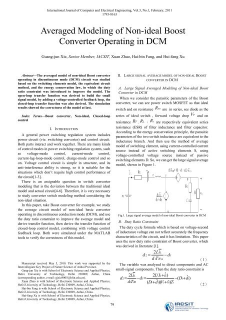
When we consider the parasitic parameters <strong>of</strong> the <strong>Boost</strong><br />
converter, we can see power switch MOSFET as that <strong>ideal</strong><br />
switch and on resistance R on<br />
are in series, see diode as the<br />
series <strong>of</strong> <strong>ideal</strong> switch , forward voltage drop V F and on<br />
resistance R F . R L 、 R c<br />
are respectively equivalent series<br />
resistance (ESR) <strong>of</strong> filter inductance and filter capacitor.<br />
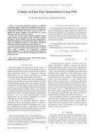
According to the energy conservation principle, the parasitic<br />
parameters <strong>of</strong> the two switch inductance are equivalent to the<br />
inductance branch. And then use the method <strong>of</strong> average<br />
model <strong>of</strong> switching element, using current-controlled current<br />
source instead <strong>of</strong> active switching elements S, using<br />
voltage-controlled voltage source instead <strong>of</strong> passive<br />
switching elements D. So, we can get the large signal average<br />
model, shown in Figure 1.<br />
Fig.1. Large signal average model <strong>of</strong> non-<strong>ideal</strong> <strong>Boost</strong> converter in DCM<br />
B. Duty Ratio Constraint<br />
The duty cycle formula which is based on voltage-second<br />
<strong>of</strong> inductance voltage can not reflect accurately the frequency<br />
characteristics <strong>of</strong> the circuit, and it has limitation. This paper<br />
uses the new duty ratio constraint <strong>of</strong> <strong>Boost</strong> converter, which<br />
was derived in literature [1].<br />
2LiL<br />
d2= −d1<br />
dTv 1 s in<br />
(1)<br />
The variable was analyzed to direct components and AC<br />
small-signal components. Then the duty ratio constraint is<br />
2LiL 2 L(<br />
IL+<br />
iˆ<br />
L) d ˆ<br />
2= − d1= − ( D1+<br />
d1)<br />
dTv 1 s i ( D ˆ<br />
1+ d1)( Vi+<br />
vˆ<br />
i)<br />
Ts<br />
(2)
International Journal <strong>of</strong> Computer and Electrical Engineering, Vol.3, No.1, February, 2011<br />
1793-8163<br />
di dTv ( D+ dˆ<br />
) ( V+<br />
vˆ<br />
) T<br />
d d 2L 2L<br />
d vap<br />
d d vap<br />
D dˆ<br />
Vap<br />
vˆ<br />
1<br />
+ 1−<br />
1<br />
−<br />
2<br />
=<br />
1<br />
+<br />
1<br />
+<br />
⎡ 2L( IL<br />
+ iˆ<br />
L<br />
) ⎤<br />
+ ⎢1<br />
−<br />
( Vzp<br />
+ vˆ<br />
zp)<br />
( D d )( Vi<br />
vˆ<br />
⎥<br />
⎣ 1<br />
+<br />
1<br />
+<br />
i<br />
) Ts<br />
⎦<br />
2 2<br />
1 L<br />
1<br />
s i 1 1 i i s<br />
= =<br />
1 2<br />
+ (3)<br />
( ) ( )( )<br />
ap<br />
(4)<br />
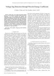
C. AC Small-Signal Model<br />
If we suppose that, the small-signal component is much<br />
less than the direct component, make the direct component is<br />
zero, and neglect the secondary small-signal product term.<br />
Then the (3) and (4) can be predigested to the (5) and (6). So<br />
we can get the small-signal linear equivalent model <strong>of</strong><br />
non-<strong>ideal</strong> <strong>Boost</strong> converter in discontinuous conduction<br />
model, shown in fig.2.<br />
( )<br />
2<br />
2<br />
d i d T v D + dˆ<br />
( V + vˆ<br />
)<br />
1<br />
1 L<br />
d + d<br />
1<br />
2<br />
2<br />
1<br />
= a vˆ<br />
+ a dˆ<br />
i<br />
=<br />
2L<br />
1<br />
s<br />
i<br />
=<br />
dv 1 ap + (1 −d1−d2)<br />
vzp<br />
= −<br />
⎡<br />
⎢1<br />
−<br />
⎢⎣<br />
( D + dˆ<br />
)( V + vˆ<br />
)<br />
1<br />
( I + iˆ<br />
)<br />
L L<br />
( D + dˆ<br />
)( V + vˆ<br />
)<br />
1<br />
2L<br />
[( V − V − V − I R ) + ( vˆ<br />
− vˆ<br />
− R iˆ<br />
)]<br />
i<br />
1<br />
1<br />
E<br />
1<br />
2 L<br />
1<br />
o<br />
o<br />
i<br />
L<br />
o<br />
i<br />
E<br />
+<br />
T<br />
∧ ∧ ∧ ∧<br />
= b vi<br />
+ b2<br />
d1+<br />
b3<br />
iL<br />
+ b4<br />
vo<br />
s<br />
⎤<br />
⎥<br />
⎥⎦<br />
1<br />
(6)<br />
Fig.2. small-signal model <strong>of</strong> <strong>Boost</strong> converter in DCM<br />
Form fig.2, we can calculate the input-to-output transfer<br />
function<br />
Gvi( s)<br />
and the control-to-output transfer function<br />
Gvd( s)<br />
are<br />
vˆ o( s)<br />
Gvi( s)<br />
=<br />
vˆ i( s )<br />
dˆ1( s ) = 0<br />
i<br />
i<br />
o<br />
i<br />
T<br />
s<br />
E<br />
L<br />
(5)<br />
1 −b1− a1( sL+ RE<br />
+ b3)<br />
E 3 C<br />
=<br />
( sL + R + b )( sR C + sRC + 1)<br />
1+ b4<br />
+<br />
RsRC ( C + 1)<br />
tt 1 4 (1 + swz1)(1 + swz2)<br />
= ⋅<br />
tt 2 3+<br />
tt 0 4 s s 2<br />
1 + + ( )<br />
Qw0 w0<br />
(7)<br />
G<br />
vd<br />
vˆ () s<br />
() s =<br />
o<br />
dˆ 1 ()ˆ s v i () s = 0<br />
b2+ a2( sL+ RE<br />
+ b3)<br />
=−<br />
( sL + RE+ b3)( sRCC + sRC + 1)<br />
1+ b4<br />
+<br />
RsRC ( C + 1)<br />
tt 4 5 (1 + swz2)(1 −swz3)<br />
= ⋅<br />
tt 2 3+<br />
tt 0 4 s s 2<br />
1 + + ( )<br />
Qw0 w0<br />
(8)<br />
The parameters <strong>of</strong> the actual <strong>Boost</strong> converter as following:<br />
input-voltage Vi<br />
= 5V<br />
, output-voltage Vo<br />
= 10V<br />
, Load<br />
current Io<br />
= 0.2A<br />
, R = 50Ω ,<br />
L=<br />
19.2μH<br />
,<br />
RL<br />
= 3.6mΩ ,<br />
C = 1000μF<br />
, RC<br />
= 2mΩ . The model<br />
number <strong>of</strong> the MOSFET which we used in this paper is<br />
2SK2690. Ron<br />
= 10mΩ , for Schottky diode RF<br />
= 1mΩ ,<br />
switching frequency<br />
fs<br />
= 50kHz<br />
, PWM outputs the Peak<br />
voltage is Vm<br />
= 1V<br />
. Then there parameters are put into the<br />
formulas as following<br />
R<br />
V<br />
E<br />
4 DR 1 on DR 2 F<br />
= ( RL+ + )<br />
3( D1+ D2)<br />
D1+ D2 D1+ D2<br />
,<br />
ap =− Vo<br />
,<br />
2LIL<br />
2= −D1<br />
1 s i<br />
IO<br />
D<br />
IL<br />
= ( D1+<br />
D2)<br />
DTV and D2<br />
R is the total equivalent resistance <strong>of</strong> the three parasitic<br />
E<br />
resistances which were calculated to branch <strong>of</strong> inductance.<br />
Then we can get<br />
D1 ≈ 0.35 , RE<br />
≈22.69mΩ , VE<br />
≈ 0.184V<br />
,<br />
IL<br />
≈ 0.43A<br />
.<br />
Put the four parameters into formula(7)and (8), then we<br />
can get formula (9) and (10).<br />
s s<br />
(1 + )(1 − )<br />
G ( ) 2.112 500000 913333<br />
vi s = ×<br />
2<br />
s ⎛ s ⎞<br />
1+ + ⎜ ⎟<br />
58.42 ⎝ 4502 ⎠ (9)<br />
s s<br />
(1 + )(1 − )<br />
G ( ) 23.696 500000 307433<br />
vd s = ×<br />
2<br />
s ⎛ s ⎞<br />
1+ + ⎜ ⎟<br />
58.42 ⎝ 4502 ⎠ (10)<br />
80
International Journal <strong>of</strong> Computer and Electrical Engineering, Vol.3, No.1, February, 2011<br />
1793-8163<br />
III. MODELLING OF BOOST CONVERTER WITH VOLTAGE<br />
FEEDBACK-LOOP CONTROL<br />
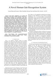
<strong>Non</strong>-<strong>ideal</strong> <strong>Boost</strong> converter with voltage-mode control is<br />
shown in fig.3. Control circuit is constituted by the controller,<br />
the PWM comparator, the clock circuit and the trigger. The<br />
circuit takes a sample <strong>of</strong> the output voltage, and then the<br />
sample signal as the feedback signal is put into the input, to<br />
make the input voltage stable.<br />
Fig.3. System structure <strong>of</strong> <strong>Boost</strong> converter with feedback-loop<br />
A. Sample Circuit and the Pulse Width Modulator<br />
( )<br />
The transfer function <strong>of</strong> the sample circuit is Hs ,<br />
and<br />
H() s vo≈<br />
vref<br />
, so<br />
Vref<br />
H() s = = 1<br />
Vo<br />
(11)<br />
The pulse width modulator is a voltage comparator<br />
actually. v c<br />
is the output signal <strong>of</strong> error amplifier and<br />
Compensation network.. It is compared with clock signal,<br />
then the comparator putout a pulse with the duty cycle is d,<br />
that control two main switch <strong>of</strong> the converter. The transfer<br />
function <strong>of</strong> the PWM comparator is<br />
ds ˆ<br />
( ) 1<br />
Fm( s)<br />
= =<br />
vˆ<br />
c( s)<br />
Vm<br />
(12)<br />
B. PID Compensator<br />
The most important component <strong>of</strong> the design is<br />
compensator in control circuit. Transfer function <strong>of</strong> the main<br />
circuit is<br />
Gvd( s ) , if there is no compensator, the transfer<br />
Gc( s ) = 1 , put it into formula (13), the open-loop<br />
function<br />
transfer function <strong>of</strong> the system. Then we can get the<br />
open-loop transfer function (14) <strong>of</strong> the system without<br />
compensator.<br />
T()<br />
s<br />
H() s Gc() s Gvd()<br />
s<br />
Vm<br />
= (13)<br />
81<br />
T<br />
() s<br />
Gvd<br />
=<br />
V<br />
() s<br />
m<br />
=<br />
⎛ s ⎞ ⎞<br />
1 ⎟⎜<br />
⎛ s<br />
⎜ + 1 − ⎟ (14)<br />
500000 307433<br />
23.7 ×<br />
⎝ ⎠⎝<br />
⎠<br />
2<br />
s ⎛ s ⎞<br />
1+<br />
+ ⎜ ⎟<br />
58.42 ⎝ 4502 ⎠<br />
And<br />
T(0) = 23.7 ⇒ 27.5dB<br />
. We can calculate out the<br />
crossover frequency wc1 = 1383 rad/<br />
s .<br />
wc<br />
1<br />
f<br />
c1 = = 220. 2Hz<br />
, and the phase margin is 92o . It<br />
2 π<br />
can be seen that, the crossover frequency is too low, response<br />
speed <strong>of</strong> the system is too slow, and the phase margin is too<br />
large. These are disadvantaged for else dynamic<br />
characteristics. So the compensation network is necessary.<br />
The PID compensator not only has the advantage that can<br />
improve the steady performance <strong>of</strong> system, but also has the<br />
more superiority to improve system dynamic performance.<br />
So we chose the PID compensation network, which is shown<br />
in fig.4.<br />
Fig.4. PID compensator in this paper<br />
Form the fig.4, we can get the transfer function <strong>of</strong> the PID<br />
compensator, which is formula (15). Then the system<br />
Open-loop transfer function after compensated is formula<br />
(16).<br />
s wL<br />
(1 + )(1 + )<br />
z<br />
Gc()<br />
s = G w s<br />
c0<br />
s s<br />
(1 + )(1 + )<br />
p1 p2<br />
.<br />
w w (15)<br />
T<br />
c<br />
() s = G ()() s T s<br />
Gc0Gvd<br />
0<br />
×<br />
V<br />
=⎛ +<br />
⎜1<br />
⎝<br />
⎛<br />
⎜1<br />
+<br />
⎝<br />
m<br />
s<br />
w<br />
s<br />
w<br />
z<br />
p1<br />
c<br />
⎞<br />
⎜<br />
⎛ w +<br />
L<br />
⎟ 1<br />
⎠⎝<br />
s<br />
⎞⎛ ⎟⎜<br />
s<br />
1 +<br />
⎠⎝<br />
w<br />
p<br />
2<br />
⎟ ⎜<br />
⎠⎛ ⎞ 1 +<br />
⎝<br />
⎞⎡<br />
⎟⎢1<br />
+<br />
⎠⎢<br />
⎣<br />
s<br />
w<br />
z2<br />
s<br />
Qw<br />
⎞<br />
⎟⎛<br />
⎟<br />
⎜1<br />
−<br />
⎠⎝<br />
⎛<br />
+<br />
⎜<br />
0 ⎝<br />
s<br />
w<br />
s<br />
w<br />
0<br />
⎟ ⎞<br />
3 ⎠ (16)<br />
2<br />
⎞ ⎤<br />
⎟ ⎥<br />
⎠ ⎥<br />
⎦<br />
The next step is to calculate parameters <strong>of</strong> the<br />
Compensation network. If we<br />
5<br />
1 2<br />
make wp<br />
= wz<br />
= 5× 10 rad /s, to cancel the zero point<br />
which was caused by output capacitance (ESR), then the<br />
z
International Journal <strong>of</strong> Computer and Electrical Engineering, Vol.3, No.1, February, 2011<br />
1793-8163<br />
open-loop transfer function is formula (17) now.<br />
s wL<br />
s<br />
(1 + )(1 + )(1 − )<br />
GG c0 vd0<br />
z<br />
z3<br />
Ts c() = GsTs c() () = w s w<br />
Vm<br />
s s s 2<br />
(1 + )[1 + + ( ) ]<br />
wp<br />
2 Qw0 w0<br />
(17)<br />
If we make crossover frequency fc<br />
<strong>of</strong> open-loop transfer<br />
function after compensation, to one fifth <strong>of</strong> the switching<br />
fs<br />
frequency , that is<br />
fc = fs 5= 50 5=<br />
10kHZ<br />
, and<br />
°<br />
45 ,<br />
ϕ m = 45<br />
suppose that phase margin is<br />
,then zero-point<br />
frequency and pole frequency respectively are<br />
o<br />
1−sinϕ<br />
m 1−sin 45<br />
fz<br />
= fc<br />
= 10× = 4.142kHz<br />
o<br />
1+ sinϕ<br />
m 1+<br />
sin45<br />
fp2<br />
= fc<br />
o<br />
1+ sinϕ<br />
m 1+<br />
sin45<br />
= 10× = 24.142kHz<br />
o<br />
1−sinϕ<br />
m 1−sin45<br />
fc<br />
fL<br />
= = 1kHz<br />
and make 10 .<br />
From<br />
T c( c) = T ( c) c( c) dB<br />
dB<br />
= 0 , we can<br />
get<br />
Gc( jwc) = 33dB⇒<br />
44.8<br />
Then<br />
dB<br />
2<br />
( f f ) 1+<br />
( f f )<br />
1+<br />
c p1<br />
c p2<br />
Gc0<br />
= Gc<br />
( jwc<br />
)<br />
2<br />
2<br />
1+<br />
( fc<br />
f<br />
z<br />
) 1+<br />
( f<br />
L<br />
fc<br />
)<br />
= 18.6<br />
s 6280<br />
18.6(1 + )(1 + )<br />
G () 26011<br />
c s =<br />
s<br />
s s<br />
(1 + )(1 + )<br />
500000 151611<br />
GG c0 vd0<br />
Tc0 = = 23.7× 18.6 = 439.1⇒52.8dB<br />
Vm<br />
s 6280 s<br />
439.1(1 + )(1 + )(1 − )<br />
T () 26011 307433<br />
c s =<br />
s<br />
2<br />
s s ⎛ s ⎞<br />
(1 + )[1 + + ⎜ ⎟ ]<br />
151611 58.42 4502<br />
o<br />
2<br />
(18)<br />
(19)<br />
⎝ ⎠ (20)<br />
1<br />
5<br />
From wp1<br />
= = 5× 10 rad /s ,<br />
RC 1 1<br />
1<br />
wL<br />
= = 6280 rad / s<br />
,<br />
RC 2 2<br />
C2+<br />
C3<br />
wp2<br />
= = 151611 rad / s<br />
RCC 2 2 3<br />
We can get R 1 = 100Ω , C1 = 20nF<br />
, R2 = 35.3kΩ ,<br />
C2 = 4.5nF<br />
, R3 = 1.82kΩ , and C3 = 0.195nF<br />
,<br />
respectively. And they meet the following formula.<br />
G<br />
c0<br />
= RC 2 2<br />
18.6<br />
R3( C2+<br />
C3)<br />
=<br />
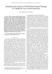
IV. SIMULATION AND EXPERIMENTAL RESULTS<br />
The small-signal <strong>of</strong> open-loop and close-loop <strong>Boost</strong><br />
converter is simulated by using MATLAB, to verify the<br />
accuracy <strong>of</strong> modeling which is proposed in this paper. The<br />
Bodes <strong>of</strong> open-loop transfer function and input-to-output<br />
transfer function are shown in fig. 5 (a), (b), respectively.<br />
Fig .6 shows the step response waveform <strong>of</strong> control-to-output<br />
in open-loop and close-loop circuit, respectively. Form the<br />
figure; we know that, crossover frequency and phase margin<br />
<strong>of</strong> open-loop transfer function in the system are more<br />
reasonable after compensation. And has decreased<br />
steady-state error in low frequency, decreased amplitude <strong>of</strong><br />
input-to-output transfer function and output impedance in<br />
low and medium frequency, strengthened the disturbance <strong>of</strong><br />
inhibitory ability, and improved the transient response speed<br />
and stability.<br />
Magnitude (dB)<br />
Phase (deg)<br />
150<br />
100<br />
50<br />
0<br />
-50<br />
360<br />
315<br />
270<br />
225<br />
180<br />
135<br />
90<br />
(a)<br />
Magnitude (dB)<br />
Phase (deg)<br />
20<br />
10<br />
0<br />
-10<br />
-20<br />
-30<br />
-40<br />
-50<br />
-60<br />
-70<br />
-80<br />
90<br />
45<br />
0<br />
-45<br />
-90<br />
Bode Diagram<br />
10 0 10 1 10 2 10 3 10 4 10 5 10 6<br />
Frequency (rad/sec)<br />
The open-loop transfer function(The broken line and real line<br />
stand for situations <strong>of</strong> before and after compensation,<br />
respectively.<br />
Bode Diagram<br />
10 2 10 3 10 4 10 5 10 6 10 7<br />
Frequency (rad/sec)<br />
(b) The input-to-output transfer function(The broken line and real<br />
line stand for situations <strong>of</strong> open-loop and close-loop circuits,<br />
respectively)<br />
Fig.5. The small-signal transfer function <strong>of</strong> <strong>Boost</strong> converter<br />
82
International Journal <strong>of</strong> Computer and Electrical Engineering, Vol.3, No.1, February, 2011<br />
1793-8163<br />
45<br />
Step Response<br />
40<br />
35<br />
30<br />
25<br />
Amplitude<br />
20<br />
15<br />
10<br />
5<br />
0<br />
0 0.2 0.4 0.6 0.8 1 1.2 1.4<br />
Time (sec)<br />
x 10 -3<br />
Fig.6. The step response waveform <strong>of</strong> control-to-output in open-loop and<br />
close-loop circuit.(The broken line and real line stand for situations <strong>of</strong> before<br />
and after compensation, respectively)<br />
V. CONCLUSION<br />
Based on the average model <strong>of</strong> switching elements method,<br />
an average <strong>of</strong> the equivalent circuit method, and the idea <strong>of</strong><br />
energy conservation law, we take <strong>Boost</strong> converter for<br />
example to study the average model <strong>of</strong> the basic non-<strong>ideal</strong><br />
converter, which is added voltage control feedback loop in<br />
DCM circuit. And we improve the model by using the duty<br />
ratio constraint; derive the open-loop transfer function and<br />
closed-loop transfer function <strong>of</strong> the model. Both to be<br />
verified the correctness <strong>of</strong> the model building, under the<br />
MATLAB simulation tools. In this paper, we have studied<br />
the modeling <strong>of</strong> voltage-control <strong>Boost</strong> converter considered<br />
parasitic parameters in DCM. The model is useful and<br />
intuitionistic, and its physical significance is clear.<br />
REFERENCES<br />
[1] Sun J, Mitchell D M, Greuel M F. <strong>Averaged</strong> modeling <strong>of</strong> PWM<br />
converters operating in discontinuous conduction mode[J]. IEEE Trans.<br />
Power Electron, 2001, 16(4): 482-492.<br />
[2] Czarkowski D, Kazimierczuk M K. Energy-conservation approach to<br />
modeling PWM dc-dc converters[J]. IEEE Trans Aerosp Electron Syst,<br />
1993, 29(3):1059–1063.<br />
[3] Davoudi A, Jatskevich J, Chapman P L. <strong>Averaged</strong> modelling <strong>of</strong><br />
switched-inductor cells considering conduction losses in discontinuous<br />
mode[J]. IET Electr. Power Appl, 2007, 1(3): 402–406.<br />
[4] Zhang Weiping. Model and Control <strong>of</strong> Switching <strong>Converter</strong> [M].<br />
Beijing: China Power Press, 2005.<br />
[5] Wang Zhenglin, Wang Kaisheng, Chen Guozheng.<br />
MATLAB/Simulink and Control System Simulation[M]. Beijing:<br />
Electronic Industry Press, 2005.<br />
[6] Sun J, Mitchell D M, Greuel M F. <strong>Averaged</strong> modeling <strong>of</strong> PWM<br />
converters operating in discontinuous conduction mode[J]. IEEE Trans.<br />
Power Electron, 2001, 16(4): 482–492.<br />
Guang-jun Xie received the B.S. degree and the M.S. degree from Hefei<br />
University <strong>of</strong> Technology, in 1992 and 1995, respectively. He received the<br />
Ph.D. degree from University <strong>of</strong> Science and Technology <strong>of</strong> China in 2002.<br />
He is now a Pr<strong>of</strong>essor <strong>of</strong> Hefei University <strong>of</strong> Technology, and his research<br />
interests include IC design, computational intelligence.<br />
83