


You also want an ePaper? Increase the reach of your titles
YUMPU automatically turns print PDFs into web optimized ePapers that Google loves.
IMS C012<br />
6 Electrical specifications<br />
6.1 DC electrical characteristics<br />
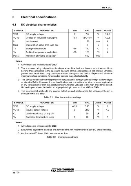
SYMBOL PARAMETER MIN MAX UNITS NOTES<br />
VDD DC supply voltage 0 7.0 V 1,2,3<br />
VI, VO Voltage on input and output pins –0.5 VDD+0.5 V 1,2,3<br />
II Input current 25 mA 4<br />
tOSC Output short circuit time (one pin) 1 s 2<br />
TS Storage temperature –65 150 o C 2<br />
TA Ambient temperature under bias –55 125 o C 2<br />
PDmax Maximum allowable dissipation 600 mW<br />
Notes<br />
1 All voltages are with respect to GND.<br />
2 This is a stress rating only and functional operation of the device at these or any other conditions<br />
beyond those indicated in the operating sections of this specification is not implied. Stresses<br />
greater than those listed may cause permanent damage to the device. Exposure to absolute<br />
maximum rating conditions for extended periods may affect reliability.<br />
3 This device contains circuitry to protect the inputs againstdamage caused by high static voltages<br />
or electrical fields. However, it is advised that normal precautions be taken to avoid application<br />
of any voltage higher than the absolute maximum rated voltages to this high impedance circuit.<br />
Unused inputs should be tied to an appropriate logic level such as VDD or GND.<br />
4 The input current applies to any input or output pin and applies when the voltage on the pin is<br />
between GND and VDD.<br />
Table 6.1 Absolute maximum ratings<br />
SYMBOL PARAMETER MIN MAX UNITS NOTES<br />
VDD DC supply voltage 4.75 5.25 V 1<br />
VI, VO Input or output voltage 0 VDD V 1,2<br />
CL Load capacitance on any pin 60 pF<br />
TA Operating temperature range 0 70 o C 3<br />
Notes<br />
1 All voltages are with respect to GND.<br />
2 Excursions beyond the supplies are permitted but not recommended; see DC characteristics.<br />
3 Air flow rate 400 linear ft/min transverse air flow.<br />
Table 6.2 Operating conditions<br />
16 /25


