


You also want an ePaper? Increase the reach of your titles
YUMPU automatically turns print PDFs into web optimized ePapers that Google loves.
IMS C012<br />
Symbol Parameter Min Nom Max Units Notes<br />
TDCLDCH ClockIn pulse width low 40 ns<br />
TDCHDCL ClockIn pulse width high 40 ns<br />
TDCLDCL ClockIn period 200 ns 1,3<br />
TDCerror ClockIn timing error 0.5 ns 2<br />
TDC1DC2 Difference in ClockIn for 2 linked devices 400 ppm 3<br />
TDCr ClockIn rise time 10 ns 4<br />
TDCf ClockIn fall time 8 ns 4<br />
Notes<br />
1 Measured between corresponding points on consecutive falling edges.<br />
2 Variation of individual falling edges from their nominal times.<br />
3 This value allows the use of 200ppm crystal oscillators for two devices connected together by<br />
a link.<br />
4 Clock transitions must be monotonic within the range VIH to VIL (table 6.3).<br />
Table 3.1 Input clock<br />
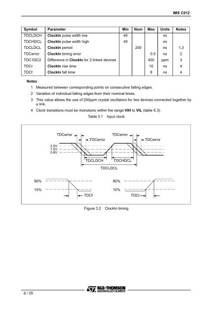
TDCerror<br />
TDCerror<br />
TDCerror<br />
TDCerror<br />
2.0V<br />
1.5V<br />
0.8V<br />
TDCLDCH<br />
TDCHDCL<br />
TDCLDCL<br />
90%<br />
90%<br />
10%<br />
TDCf<br />
10%<br />
TDCr<br />
Figure 3.2<br />
ClockIn timing<br />
6/25


