design and implementation of thyristor switched shunt capacitors a ...
design and implementation of thyristor switched shunt capacitors a ...
design and implementation of thyristor switched shunt capacitors a ...
You also want an ePaper? Increase the reach of your titles
YUMPU automatically turns print PDFs into web optimized ePapers that Google loves.
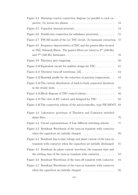
Figure 3.4 Discharge reactor connection diagram (a) parallel to each capacitor,<br />
(b) across two phases. . . . . . . . . . . . . . . . . . . . . . 53<br />
Figure 3.5 Capacitor internal structure. . . . . . . . . . . . . . . . . . . 54<br />
Figure 3.6 Double-star connection for unbalance protection. . . . . . . . 55<br />
Figure 3.7 PSCAD model <strong>of</strong> the (a) TSC circuit, (b) harmonic extraction. 57<br />
Figure 3.8 Frequency characteristics <strong>of</strong> TSC <strong>and</strong> the passive filter located<br />
in TKİ, Orhaneli/Bursa. The passive filters are tuned to 5th (240 Hz)<br />
<strong>and</strong> 7 th (340 Hz) harmonics. . . . . . . . . . . . . . . . . . . . . . . 58<br />
Figure 3.9 Thyristor gate triggering. . . . . . . . . . . . . . . . . . . . . 60<br />
Figure 3.10 Equivalent circuit for snubber <strong>design</strong> for TSC. . . . . . . . . 61<br />
Figure 3.11 Thyristor turn-<strong>of</strong>f waveforms, [43]. . . . . . . . . . . . . . . . 62<br />
Figure 3.12 Heatsink pr<strong>of</strong>ile for the reduction <strong>of</strong> junction temperature. . 64<br />
Figure 3.13 The current distribution <strong>of</strong> back-to-back connected <strong>thyristor</strong>s<br />
in the steady state. . . . . . . . . . . . . . . . . . . . . . . . . . . . 65<br />
Figure 3.14 Block diagram <strong>of</strong> TSC control scheme. . . . . . . . . . . . . . 66<br />
Figure 3.15 The view <strong>of</strong> EU control card <strong>design</strong>ed for TSC. . . . . . . . . 68<br />
Figure 3.16 The connection scheme <strong>of</strong> the microcontroller, type PIC16F877. 69<br />
Figure 4.1 Laboratory prototype <strong>of</strong> Thyristor <strong>and</strong> Contactor <strong>switched</strong><br />
<strong>shunt</strong> filter. . . . . . . . . . . . . . . . . . . . . . . . . . . . . . . . . 76<br />
Figure 4.2 Circuit representations <strong>of</strong> four different switching scheme. . . 77<br />
Figure 4.3 Resultant Waveforms <strong>of</strong> the turn-on transient with contactor<br />
when the <strong>capacitors</strong> are initially charged. . . . . . . . . . . . . . . . 80<br />
Figure 4.4 Resultant line-to-line voltage <strong>and</strong> phase current <strong>of</strong> the turn-on<br />
transient with contactor when the <strong>capacitors</strong> are initially discharged. 81<br />
Figure 4.5 Resultant 3φ phase current waveform, the response time <strong>and</strong><br />
the settling time <strong>of</strong> the turn-on transient with contactor. . . . . . . 83<br />
Figure 4.6 Resultant Waveforms <strong>of</strong> the turn-<strong>of</strong>f transient with contactor. 84<br />
Figure 4.7 Resultant Waveforms <strong>of</strong> the turn-on transient with contactor<br />
when the <strong>capacitors</strong> are initially charged. . . . . . . . . . . . . . . . 86<br />
xiv


