- Page 1 and 2: DESIGN AND IMPLEMENTATION OF THYRIS
- Page 3 and 4: I hereby declare that all informati
- Page 5 and 6: ÖZ TRİSTÖR ANAHTARLAMALI ŞÖNT
- Page 7 and 8: ACKNOWLEDGMENTS I would like to exp
- Page 9 and 10: 2.3 Switching Performance of TSC .
- Page 11 and 12: LIST OF TABLES TABLES Table 1.1 Cur
- Page 13 and 14: Figure 2.9 (a) Equivalent circuit r
- Page 15 and 16: Figure 4.8 Resultant line-to-line v
- Page 17 and 18: Figure 4.38 3 Phase current wavefor
- Page 19 and 20: CHAPTER 1 INTRODUCTION 1.1 Power Qu
- Page 21 and 22: this disturbance since they do not
- Page 23 and 24: driving algorithm and it has to wit
- Page 25 and 26: how to improve the transient respon
- Page 27 and 28: From the practical view, the less t
- Page 29 and 30: CHAPTER 2 PROBLEM DEFINITION AND PR
- Page 31 and 32: as switching devices instead of ant
- Page 33 and 34: Directly Connected Clients 35 33 30
- Page 35 and 36: 2.2.2 Harmonic Filtration A pure si
- Page 37 and 38: components dramatically. The follow
- Page 39 and 40: 20A 20A 15A 15A Line Current 10A Li
- Page 41 and 42: VS RS XS VL Source Load IL Ic Compe
- Page 43 and 44: a couple of cycles. However, at lea
- Page 45 and 46: i + + VT - T1 T2 V + VC - L C Figur
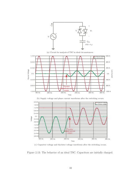
- Page 47 and 48: 2.15 shows that there are some comp
- Page 49: waveform directly follows the sourc
- Page 53 and 54: components parallel to the thyristo
- Page 55 and 56: Ls Coupling Transformer V TCR TSC L
- Page 57 and 58: +1.0 Reactive Power, Q (pu) Inducti
- Page 59 and 60: V V max V max = voltage limit I Cma
- Page 61 and 62: power system. Voltage source conver
- Page 63 and 64: timing of switching must be when th
- Page 65 and 66: Table 3.1: Type of the excavators a
- Page 67 and 68: 3.3 Selection Criterion of Capacito
- Page 69 and 70: minutes should be given to self-dis
- Page 71 and 72: possible in order to achieve a tran
- Page 73 and 74: advantage. It is not affected by th
- Page 75 and 76: (a) (b) Figure 3.7: PSCAD model of
- Page 77 and 78: this value is at least twice of the
- Page 79 and 80: of the reverse recovery current and
- Page 81 and 82: curve in its datasheet should be ta
- Page 83 and 84: Figure 3.13: The current distributi
- Page 85 and 86: stays in inductive or capacitive re
- Page 87 and 88: ”ENB A, ENB B and ENB C” are co
- Page 89 and 90: 3.7 Key Points in Design of TSC Cab
- Page 91 and 92: chapter, some basic calculations to
- Page 93 and 94: CHAPTER 4 EXPERIMENTAL RESULTS 4.1
- Page 95 and 96: (a) Contactor Switched Plain Capaci
- Page 97 and 98: ated capacitor current. This inrush
- Page 99 and 100: current. Line-to-line voltage is al
- Page 101 and 102:
(a) Three phase current waveform at
- Page 103 and 104:
4.2.2 Contactor Switched Shunt Filt
- Page 105 and 106:
to high inrush current causes a con
- Page 107 and 108:
(a) Voltage Waveform across the cap
- Page 109 and 110:
(a) Voltage Waveform across the cap
- Page 111 and 112:
This transient has also negligible
- Page 113 and 114:
(a) Three phase current waveform at
- Page 115 and 116:
Figure 4.17: Resultant 3φ Capacito
- Page 117 and 118:
(a) Voltage Waveform across the cap
- Page 119 and 120:
Figure 4.21: Resultant line-to-line
- Page 121 and 122:
Figure 4.24: Firing pulses, voltage
- Page 123 and 124:
566 uF 2x6.0 MVA TM 34.5 kV 500 / 5
- Page 125 and 126:
Experimental results will be presen
- Page 127 and 128:
+1.6 +0.66 Thyristor Voltage (kV) -
- Page 129 and 130:
+1.5 +1.0 Capacitor Voltage (kV) +0
- Page 131 and 132:
+1.5 +1.0 Capacitor Voltage (kV) +0
- Page 133 and 134:
increase in current can be approxim
- Page 135 and 136:
would be given to the supply voltag
- Page 137 and 138:
250 1 cycle transient fft 200 I Pha
- Page 139 and 140:
4.4 TSC Cabinet Interior Equipment
- Page 141 and 142:
4.5 Discussion In contactor or thyr
- Page 143 and 144:
• Delta-connected TSC topology is
- Page 145 and 146:
[13] Tabandeh, M., Alavi, M.H., Mar
- Page 147 and 148:
[38] Bilgin, H.F., “Design and Im
- Page 149 and 150:
Since the roots of this equation ar
- Page 151 and 152:
APPENDIX B DISTINCTIVE CURVES OF TH
- Page 153 and 154:
135 Figure B.2: Stored charge and r
- Page 155 and 156:
APPENDIX C DETAILS OF THE CONTROL C
- Page 157 and 158:
139 Figure C.2: P-CAD 2002 Schemati
- Page 159 and 160:
141 Figure C.4: P-CAD 2002 Schemati
- Page 161 and 162:
143 Figure C.6: P-CAD 2002 Schemati
- Page 163 and 164:
145 Figure C.8: P-CAD 2002 Schemati
- Page 165 and 166:
147 Figure C.10: P-CAD 2002 Schemat
- Page 167 and 168:
149 Figure D.1: General view of the
- Page 169 and 170:
APPENDIX E APPLICATION MODEL OF THE
- Page 171 and 172:
153 Figure E.2: 3 dimensional plot
- Page 173 and 174:
155 Figure F.1: Installed SVC syste
- Page 175 and 176:
157 Figure F.3: Installed SVC syste


