design and implementation of thyristor switched shunt capacitors a ...
design and implementation of thyristor switched shunt capacitors a ...
design and implementation of thyristor switched shunt capacitors a ...

You also want an ePaper? Increase the reach of your titles
YUMPU automatically turns print PDFs into web optimized ePapers that Google loves.
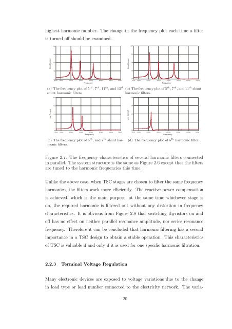
highest harmonic number. The change in the frequency plot each time a filter<br />
is turned <strong>of</strong>f should be examined.<br />
20A<br />
20A<br />
15A<br />
15A<br />
Line Current<br />
10A<br />
Line Current<br />
10A<br />
5A<br />
5A<br />
0A<br />
50Hz<br />
100Hz 200Hz 300Hz 400Hz 500Hz 600Hz 700Hz<br />
0A<br />
50Hz<br />
100Hz 200Hz 300Hz 400Hz 500Hz 600Hz 700Hz<br />
Frequency<br />
Frequency<br />
(a) The frequency plot <strong>of</strong> 5 th , 7 th , 11 th , <strong>and</strong> 13 th<br />
<strong>shunt</strong> harmonic filters.<br />
(b) The frequency plot <strong>of</strong> 5 th , 7 th , <strong>and</strong> 11 th <strong>shunt</strong><br />
harmonic filters.<br />
20A<br />
20A<br />
15A<br />
15A<br />
Line Current<br />
10A<br />
Line Current<br />
10A<br />
5A<br />
5A<br />
0A<br />
50Hz 100Hz 200Hz 300Hz 400Hz 500Hz 600Hz 700Hz<br />
Frequency<br />
0A<br />
50Hz<br />
100Hz 200Hz 300Hz 400Hz 500Hz 600Hz 700Hz<br />
Frequency<br />
(c) The frequency plot <strong>of</strong> 5 th , <strong>and</strong> 7 th <strong>shunt</strong> harmonic<br />
filters.<br />
(d) The frequency plot <strong>of</strong> 5 th harmonic filter.<br />
Figure 2.7: The frequency characteristics <strong>of</strong> several harmonic filters connected<br />
in parallel. The system structure is the same as Figure 2.6 except that the filters<br />
are tuned to the harmonic frequencies this time.<br />
Unlike the above case, when TSC stages are chosen to filter the same frequency<br />
harmonics, the filters work more efficiently. The reactive power compensation<br />
is achieved, which is the main purpose, at the same time whichever stage is<br />
on, the required harmonic is filtered out without any distortion in frequency<br />
characteristics. It is obvious from Figure 2.8 that switching <strong>thyristor</strong>s on <strong>and</strong><br />
<strong>of</strong>f has no effect on neither parallel resonance amplitude, nor series resonance<br />
frequency. Therefore it can be concluded that harmonic filtering has a second<br />
importance in a TSC <strong>design</strong> to obtain a stable operation. This characteristics<br />
<strong>of</strong> TSC is valuable if <strong>and</strong> only if it is used for one specific harmonic filtration.<br />
2.2.3 Terminal Voltage Regulation<br />
Many electronic devices are exposed to voltage variations due to the change<br />
in load type or load number connected to the electricity network. The varia-<br />
20