MASTER BOOK – SECTION 1 Rev. 2007 - EKA Group
MASTER BOOK – SECTION 1 Rev. 2007 - EKA Group
MASTER BOOK – SECTION 1 Rev. 2007 - EKA Group

You also want an ePaper? Increase the reach of your titles
YUMPU automatically turns print PDFs into web optimized ePapers that Google loves.
4.3 <strong>–</strong> INSTALLATION OF RAISED<br />
FLOOR WITH MPS<br />
1) The adoption of an MPS substructure requires that the slab is laid as flat as possible; the more this<br />
recommendation is followed, the better the final result and stability of the raised floor and the easier the<br />
installation.<br />
2) Start from 2 walls that are as much as possible right-angled; fasten two tight wires, at a distance of not more<br />
than 58 cm from the wall, and at about 2-3 cm above the finished floor. Calculate their perpendicularity by<br />
means of the 3-4-5 method (Pythagoras’ Theorem). Check that there will be no panel crop-ends against the<br />
wall which are shorter than 15 cm.<br />
3) Assemble the MPS pedestals (base + column + gaskets) approximately adapting them to the height<br />
required in the design measurement.<br />
4) Start the installation by laying the first panel on four pedestals, placing it with two sides exactly along the<br />
right-angled wires. Make sure that the mentioned wires do not meet any obstacles and have not been<br />
diverted.<br />
5) Proceeding by placing two parallel rows of panels and pedestals, carefully following the longer wire.<br />
6) Glue the bases of the pedestals to the floor with a suitable glue. Apply the glue under the base of the<br />
pedestal.<br />
7) The complete pedestal is then positioned and settled in its place by pressing it vertically until the glue<br />
squirts out from under the base perimeter.<br />
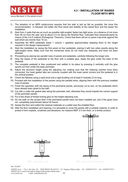
8) Adjust the structure height using the adjusting nut, making sure that the indexing notches have been<br />
connected, the head gasket tabs are correctly coupled with the lower panel corners and the pedestal is in<br />
the vertical position.<br />
9) Check the flatness using a spirit level and a rigid levelling rod at least 5 modules (3 m) long.<br />
10) Proceed with the installation of the panels using the parallel wires, aligning them with the previous installed<br />
rows of panels.<br />
11) Finish the operation with the laying of the perimetral panels, previously cut to size, on the pedestals which<br />
have already been glued to the slab.<br />
12) Cut with a cutter the gasket tabs along the perimeter wall, otherwise they would impede the correct support<br />
of the perimeter panels.<br />
13) Put a few drops of thread locking glue on the height adjusting nuts.<br />
14) Do not walk on the access floor if the perimetral panels have not been installed yet, and if the glues have<br />
not completely polymerized (about 24 hours).<br />
15) Sweep the floor and collect the residual materials on a pallet near the installed floor.<br />
16) After the floor installation and cleaning, it is advisable to cover the panels with a suitable material, in order to<br />
protect it from impacts, scratches and abrasions, for instance MDF 2-3 mm thick, or a similar product.<br />
MPS structure low<br />
MPS structure standard<br />
<strong>Rev</strong>. 01.08.07<br />
NESITE S.p.A. <strong>–</strong> Via L. Da Vinci, 20 <strong>–</strong> 35028 PIOVE DI SACCO <strong>–</strong> Z.I. Tognana (Padova) Italy <strong>–</strong> Tel. +39.049.9713311 <strong>–</strong> Fax +39.049.9713313<br />
NESITE S.p.A. reserves the right to change technical data without notice<br />
www.nesite.com e-mail : nesite@nesite.com<br />
43