GE SitePro Brochure.pdf - Gruber Power
GE SitePro Brochure.pdf - Gruber Power
GE SitePro Brochure.pdf - Gruber Power
Create successful ePaper yourself
Turn your PDF publications into a flip-book with our unique Google optimized e-Paper software.
g<br />
<strong>GE</strong> Digital Energy<br />
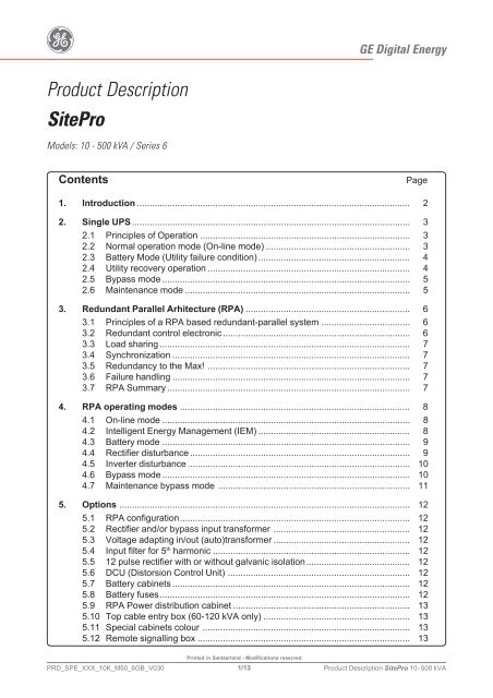
Product Description<br />
<strong>SitePro</strong><br />
Models: 10 - 500 kVA / Series 6<br />
Contents<br />
Page<br />
1. Introduction ............................................................................................................ 2<br />
2. Single UPS .............................................................................................................. 3<br />
2.1 Principles of Operation ................................................................................... 3<br />
2.2 Normal operation mode (On-line mode) ......................................................... 3<br />
2.3 Battery Mode (Utility failure condition) ............................................................ 4<br />
2.4 Utility recovery operation ................................................................................ 4<br />
2.5 Bypass mode .................................................................................................. 5<br />
2.6 Maintenance mode ......................................................................................... 5<br />
3. Redundant Parallel Arhitecture (RPA) ................................................................. 6<br />
3.1 Principles of a RPA based redundant-parallel system ................................... 6<br />
3.2 Redundant control electronic .......................................................................... 6<br />
3.3 Load sharing ................................................................................................... 7<br />
3.4 Synchronization .............................................................................................. 7<br />
3.5 Redundancy to the Max! ................................................................................ 7<br />
3.6 Failure handling .............................................................................................. 7<br />
3.7 RPA Summary ................................................................................................ 7<br />
4. RPA operating modes ........................................................................................... 8<br />
4.1 On-line mode .................................................................................................. 8<br />
4.2 Intelligent Energy Management (IEM) ............................................................ 8<br />
4.3 Battery mode .................................................................................................. 9<br />
4.4 Rectifier disturbance ....................................................................................... 9<br />
4.5 Inverter disturbance ........................................................................................ 10<br />
4.6 Bypass mode .................................................................................................. 10<br />
4.7 Maintenance bypass mode ............................................................................ 11<br />
TEMPORARY<br />
5. Options ................................................................................................................... 12<br />
5.1 RPA configuration........................................................................................... 12<br />
5.2 Rectifier and/or bypass input transformer ...................................................... 12<br />
5.3 Voltage adapting in/out (auto)transformer ...................................................... 12<br />
5.4 Input filter for 5 th harmonic .............................................................................. 12<br />
5.5 12 pulse rectifier with or without galvanic isolation......................................... 12<br />
5.6 DCU (Distorsion Control Unit) ........................................................................ 12<br />
5.7 Battery cabinets .............................................................................................. 12<br />
5.8 Battery fuses................................................................................................... 12<br />
5.9 RPA <strong>Power</strong> distribution cabinet ...................................................................... 13<br />
5.10 Top cable entry box (60-120 kVA only) .......................................................... 13<br />
5.11 Special cabinets colour .................................................................................. 13<br />
5.12 Remote signalling box .................................................................................... 13<br />
PRD_SPE_XXX_10K_M50_6GB_V030<br />
Printed in Switzerland - Modifications reserved<br />
1/13<br />
Product Description <strong>SitePro</strong> 10-500 kVA
g<br />
<strong>GE</strong> Digital Energy<br />
1. INTRODUCTION<br />
<strong>SitePro</strong> family is an Uninterruptible <strong>Power</strong> Supply (UPS) designed to meet highest requirements<br />
concerning reliability and quality of electrical energy supply even in the most demanding applications.<br />
The <strong>SitePro</strong> UPS are based on double conversion technology and are ”true On-line” or “continuous<br />
operation” UPS with integrated output transformer for galvanic isolation.<br />
The new term “VFI” (Voltage & Frequency Independent) applies for this concept, where the AC<br />
input voltage is first converted to DC voltage, also used to charge the battery, and then re-converted<br />
to AC voltage to supply the load.<br />
This design and product topology is recognized as the only one able to reach the highest requirements<br />
of power reliability for critical applications.<br />
High output power quality, excellent behavior with dynamic load variations, “zero” interruption<br />
transfer time, adequate overvoltage protection and filtering are some of the most important features<br />
of this kind of UPS.<br />
Thanks to RPA (Redundant Parallel Architecture) the system power can be expanded by paralleling<br />
units or the system reliability can be increased by adding redundant units.<br />
The double conversion static UPS system <strong>SitePro</strong> consists of the following main building blocks:<br />
K6<br />
Q4 Rectifier Inverter<br />
F8-F9<br />
Automatic Bypass<br />
Manual Bypass<br />
SSM<br />
K7<br />
<strong>SitePro</strong> 10 - 40 kVA<br />
Q2<br />
Q1<br />
LOAD<br />
SP_010-040_S6_block diagram_01GB<br />
Q4<br />
Automatic Bypass<br />
K3<br />
Rectifier<br />
Manual Bypass<br />
K6<br />
Inverter<br />
SP_060-120_S6_block diagram_02GB<br />
Rectifier/Charger<br />
The rectifier converts the 3-phase mains input voltage into a controlled and regulated DC-voltage<br />
in order to supply the inverter and charge the battery.<br />
The standard version employs software control to limit rectifier start-up current and voltage (soft<br />
start procedure).<br />
TEMPORARY<br />
Inverter<br />
Converts the DC-voltage into 3-phase alternating voltage with constant amplitude and stable<br />
frequency.<br />
Thanks to the inverter and its output transformer, the output voltage is unaffected by mains<br />
disturbances or mains failure. The <strong>SitePro</strong> uses an IGBT based inverter with SVM (Space Vector<br />
Modulation) regulation to achieve extremely high efficiency even at partial load conditions and<br />
extremely low distortion in case of non-linear load conditions.<br />
SSM<br />
K7<br />
<strong>SitePro</strong> 60 - 120 kVA<br />
Q2<br />
Q1<br />
LOAD<br />
Q4<br />
Q3a<br />
Automatic Bypass<br />
Rectifier<br />
Manual Bypass<br />
K6<br />
Inverter<br />
SSM<br />
K7<br />
<strong>SitePro</strong> 150 - 500 kVA<br />
Q2<br />
Q1<br />
LOAD<br />
SP_150-500_S6_block diagram_01GB<br />
Electronic bypass<br />
Serves to temporarily transfer the load automatically and interruption-free to mains in case of overload<br />
or inverter failures conditions. In the case of an overload, the load will automatically be re-transferred<br />
to the inverter after an adjustable time interval.<br />
Maintenance bypass<br />
Serves to transfer the load interruption-free to mains for maintenance purposes.<br />
Battery<br />
The battery is used to supply the inverter with energy in case of mains failures.<br />
It is normally selected to supply the inverter at rated load during the required back-up time.<br />
PRD_SPE_XXX_10K_M50_6GB_V030<br />
Printed in Switzerland - Modifications reserved<br />
2/13<br />
Product Description <strong>SitePro</strong> 10-500 kVA
g<br />
<strong>GE</strong> Digital Energy<br />
2. SINGLE UPS<br />
2.1 Principles of Operation<br />
To ensure an uninterrupted supply of the load under all operating conditions, the standard <strong>SitePro</strong><br />
UPS already offers four different operating modes!<br />
Additionally to the primary AC / DC / AC energy supply, connected batteries and a static bypass<br />
offer two more possibilities to assure energy to the critical load.<br />
The fact of having multiple energy sources for the load greatly increases the Ioad’s reliability and<br />
introduces also the concept of redundancy.<br />
This, for the S (single) model internal, redundancy concept, will be emphasized when the Redundant<br />
Parallel Architecture (RPA) configuration is discussed.<br />
Transfer from one operating mode to another takes place interruption-free for the load.<br />
<strong>SitePro</strong> offers all the following operating modes as a standard:<br />
• Normal mode (On-line mode)<br />
• Battery mode<br />
• Bypass mode<br />
• Maintenance bypass mode<br />
2.2 Normal operation mode (On-line mode)<br />
During normal in operation, the rectifier converts input AC power to DC.<br />
The DC power provides input power for the inverter and charging power for the battery.<br />
The inverter converts the DC power to continuous and regulated AC power, which supplies the<br />
critical load.<br />
The control panel reports the battery charge status and the expected backup time with the actual<br />
load.<br />
TEMPORARY<br />
MANUAL<br />
BYPASS<br />
MAINS/UTILITY<br />
INPUT<br />
AUTOMATIC<br />
BYPASS<br />
LOAD<br />
RECTIFIER<br />
INVERTER<br />
BATTERY<br />
SP_150-500_S6_bd-normal_01GB<br />
PRD_SPE_XXX_10K_M50_6GB_V030<br />
Printed in Switzerland - Modifications reserved<br />
3/13<br />
Product Description <strong>SitePro</strong> 10-500 kVA
g<br />
<strong>GE</strong> Digital Energy<br />
2.3 Battery Mode (Utility failure condition)<br />
In the event of a utility failure, the DC power to the inverter will be provided by the battery in order<br />
to maintain a continuous AC power to the load for the specified time at the rated load (or longer at<br />
a reduced load), until the battery voltage reaches the lower limit of the inverter operation capability.<br />
During the discharge, the LCD screen displays the estimated time the battery can support the<br />
critical load.<br />
Prior to the battery completely discharging, the alarm “Stop operation” (load shutdown imminent)<br />
warns the operator that the battery is almost discharged and the UPS is about to shut down.<br />
“Stop Operation” time activation is settable.<br />
MANUAL<br />
BYPASS<br />
MAINS/UTILITY<br />
INPUT<br />
RECTIFIER<br />
2.4 Utility recovery operation<br />
AUTOMATIC<br />
BYPASS<br />
BATTERY<br />
INVERTER<br />
TEMPORARY<br />
LOAD<br />
SP_150-500_S6_bd-battery_01GB<br />
The load is powered from the battery if the utility power does not conform to the specified parameters.<br />
As soon as the AC input power recovers, the rectifier starts up automatically (soft-start) supplying<br />
the DC power and recharging the battery.<br />
During utility mains recovery, in case a utility power failure is major than the back-up time, the<br />
battery is recharged enough to ensure a minimum time of operation with the present load, the<br />
inverter starts automatically and the load will be transferred from the static bypass back to the<br />
inverter (normal mode).<br />
No additional operations are necessary.<br />
MANUAL<br />
BYPASS<br />
MAINS/UTILITY<br />
INPUT<br />
AUTOMATIC<br />
BYPASS<br />
LOAD<br />
RECTIFIER<br />
INVERTER<br />
BATTERY<br />
SP_150-500_S6_bd-normal_01GB<br />
PRD_SPE_XXX_10K_M50_6GB_V030<br />
Printed in Switzerland - Modifications reserved<br />
4/13<br />
Product Description <strong>SitePro</strong> 10-500 kVA
g<br />
<strong>GE</strong> Digital Energy<br />
2.5 Bypass mode<br />
In normal operation, the load is permanently supplied by the inverter.<br />
When the control system detects a fault in the inverter, an overload , overtemperature or a shortcircuit<br />
condition, the static switch transfers the critical load to the utility without interruption.<br />
When the inverter recovers, or the overload, overtemperature or short-circuit condition is corrected,<br />
the load will be transferred automatically back to the inverter interruption-free.<br />
If the UPS is transferred to bypass mode for maintenance purpose, any an alarm condition is<br />
notified, however, if the UPS is unable to return to normal mode following an automatic transfer to<br />
bypass mode, an alarm is activated.<br />
The admissible transfer time is settable.<br />
MAINS/UTILITY<br />
INPUT<br />
2.6 Maintenance mode<br />
RECTIFIER<br />
AUTOMATIC<br />
BYPASS<br />
BATTERY<br />
INVERTER<br />
MANUAL<br />
BYPASS<br />
TEMPORARY<br />
LOAD<br />
SP_150-500_S6_bd-automatic bypass_01GB<br />
The maintenance bypass circuit consist of two manual Switches, which permits, for maintenance<br />
purposes, to transfer of the load directly to the unconditioned AC power without interruption.<br />
MANUAL<br />
BYPASS<br />
MAINS/UTILITY<br />
INPUT<br />
AUTOMATIC<br />
BYPASS<br />
LOAD<br />
RECTIFIER<br />
INVERTER<br />
BATTERY<br />
SP_150-500_S6_bd-manual bypass_01GB<br />
PRD_SPE_XXX_10K_M50_6GB_V030<br />
Printed in Switzerland - Modifications reserved<br />
5/13<br />
Product Description <strong>SitePro</strong> 10-500 kVA
g<br />
<strong>GE</strong> Digital Energy<br />
3. REDUNDANT PARALLEL ARCHITECTURE (RPA)<br />
Whenever <strong>SitePro</strong> UPS are applied in Mission Critical Applications, a single unit protection is no<br />
longer sufficient.<br />
To respond to this requirement for the highest level of reliability, <strong>GE</strong> developed a redundant-parallel<br />
system, known as RPA (Redundant Parallel Architecture), an <strong>GE</strong> exclusivity.<br />
To achieve highest levels of reliability, two or more <strong>SitePro</strong> are linked in a peer-to-peer configuration,<br />
concurrently supplying the load.<br />
Thanks to the total modularity of RPA, the system can be easily expanded to higher power or<br />
higher redundancy levels at any time under full working conditions.<br />
3.1 Principles of a RPA based redundant-parallel system<br />
RPA (Redundant Parallel Architecture) is a unique system to provide highest power reliability,<br />
respecting the reflections, patterns and standards as defined by the relevant industries for mission<br />
critical applications for the technical term “redundancy”.<br />
Fundamental elements to the term “redundancy” are:<br />
• No single failure point<br />
• Fault tolerance - means the system can accept any type of one single failure without any influence<br />
to the critical function – in UPS applications this means to accept any event from a simple<br />
fuse failure to the failure of an entire inverter without any influence to the load.<br />
• Error masking – error isolation and error removal under active load conditions.<br />
• Restore full operating condition without by-pass operation for the critical load.<br />
To comply with term “redundancy”, a UPS system generally needs to be designed as follows:<br />
• Decentralized by-pass concept.<br />
• Decentralized control electronics.<br />
• Redundant (n+1) operation and control for critical functions as “Synchronization” and “Bypass<br />
operation”.<br />
• Redundant communication link between individual units.<br />
TEMPORARY<br />
Note:<br />
not every parallel UPS is a redundant UPS; some UPS manufacturers honestly<br />
disclose this difference, some promote parallel UPS as “redundant”, without<br />
respecting the above rules!<br />
3.2 Redundant control electronic<br />
Each individual unit has its own operation controller (Microprocessor) for redundant-parallel operation.<br />
When active, all controllers continuously intercommunicate in order to manage the entire<br />
system in a democratic way.<br />
Example:<br />
If, in a RPA system of 3 UPS “A”, “B”, “C”, unit “A” detects a utility failure and “B” and “C” cannot “see” this<br />
failure, “A” will be isolated and it’s functions will be managed by the two remaining units as long as there<br />
is no immediate risk for the critical load RPA does not have any “Master-Slave” condition.<br />
PRD_SPE_XXX_10K_M50_6GB_V030<br />
Printed in Switzerland - Modifications reserved<br />
6/13<br />
Product Description <strong>SitePro</strong> 10-500 kVA
g<br />
<strong>GE</strong> Digital Energy<br />
3.3 Load sharing<br />
The RPA operation controller is the supervisor to monitor the equal load distribution on each UPS.<br />
It does this by separately regulating the power exchange (which must be as near as possible to<br />
zero) between each single installation.<br />
To achieve this, the RPA operation circuitry engages in continuous calculation of an index value, defined<br />
by the sum of the measured values of all the single installations divided by the number of units<br />
active. This index value is then passed to the individual units as a reference parameter for the<br />
regulation of the inverter.<br />
Due to the extremely precise synchronization (see below), the load sharing follows physical rules in a<br />
natural (and dynamic) way, the need to intercept for the controller is therefor almost not existent.<br />
3.4 Synchronization<br />
The most important feature of the RPA operation is to ensure the synchronization of the entire<br />
system – on one hand between all RPA UPS’s and on the other hand via the bypass’s to utility.<br />
With advanced signal elaboration and enhanced high precision tracking, RPA reaches the highest<br />
precision in synchronization in the industry.<br />
The unique precision of 0.05 milliseconds between units allows a high speed, voltage based, load sharing.<br />
3.5 Redundancy to the Max!<br />
With RPA, principally all modules as rectifier, inverter, bypass, controllers and communications are<br />
redundant. There are no single failure points, centralized elements or Master-Slave situations.<br />
3.6 Failure handling<br />
RPA is able to keep a single unit isolated in the event of disturbances in the redundant-parallel system.<br />
In this case, the RPA logic of the affected unit will communicate the “problem” to the shared system<br />
information. If necessary, RPA will automatically “isolate” the affected unit until the problem is solved.<br />
The level of isolation is defined by system parameters, the goal to keep the load UPS protected as<br />
long as possible, has the highest importance.<br />
As a consequence, an affected unit may be managed by the system and continue to work in RPA<br />
or it may be totally excluded from the process.<br />
For example: the measured values received from a “isolated” UPS are not taken into account when<br />
the index value for the load sharing is calculated.<br />
As long as the output of the remaining UPS’s is enough to supply the load, RPA will remain active<br />
and feed the load via the inverters. It may be, the remaining inverters are no longer able to provide<br />
“redundancy”, in this case RPA acts as “parallel” system. In case the available power is insufficient<br />
(overload condition), RPA will switch all units to bypass mode.<br />
TEMPORARY<br />
3.7 RPA Summary<br />
Redundant Inverters: RPA sustains the load as long as possible via the paralleled inverters of the<br />
true On-line individual units. If one or more single units suffer a disturbance, the then parallel<br />
system only switches to ”bypass” mode when the total power of all the available inverters is no<br />
longer sufficient to sustain the load in ”On-line” mode.<br />
Decentralized Bypass and redundant control: Even at full load the static bypass of a single<br />
installation can fail without jeopardizing the power supply of the load.<br />
Redundant Microprocessors: Due to multiple redundancy and shared tasks there is no common<br />
point of failure or bottleneck.<br />
PRD_SPE_XXX_10K_M50_6GB_V030<br />
Printed in Switzerland - Modifications reserved<br />
7/13<br />
Product Description <strong>SitePro</strong> 10-500 kVA
g<br />
<strong>GE</strong> Digital Energy<br />
4. RPA operating modes<br />
In order to ensure no-break power supply under all operating conditions, the RPA system has<br />
several operating modes.<br />
Transfers from one mode to the other are performed without interruption for the load.<br />
4.1 On-line mode<br />
Mains<br />
Load<br />
Q2<br />
K6<br />
Q4<br />
K3<br />
SSM<br />
K7<br />
Q1<br />
When the system is in On-line mode, all the rectifiers<br />
as well as all the inverters of the installation are<br />
operating.<br />
4.2 Intelligent Energy Management (IEM)<br />
Mains<br />
Q2<br />
K6<br />
Q4<br />
Q2<br />
K6<br />
Q4<br />
Q2<br />
K6<br />
Q4<br />
Q2<br />
K6<br />
Q4<br />
Q2<br />
K6<br />
Q4<br />
K3<br />
K3<br />
K3<br />
K3<br />
K3<br />
SSM<br />
SSM<br />
SSM<br />
SSM<br />
SSM<br />
K7<br />
K7<br />
K7<br />
K7<br />
K7<br />
Q1<br />
Q1<br />
Load<br />
The utility supplies the parallel-connected rectifiers.<br />
Each rectifier supply both battery and inverter by<br />
converting the utility AC voltage into a DC voltage.<br />
The load is equally shared by all the inverters.<br />
IEM is a award winning software package, which<br />
allows RPA systems to save energy during low load<br />
conditions.<br />
Individual inverters, which are not required to sustain<br />
the load, can automatically be switched off to<br />
save energy.<br />
Depending on load level, inverters are switched off<br />
cyclically, so that every UPS has the same amount<br />
of operating hours over a period of time.<br />
The load is sustained by the remaining inverters.<br />
Furthermore, the customer can define if the rectifiers<br />
remain operational to charge the batteries on those installations<br />
that have their inverters switched off or if the<br />
rectifiers are switched off.<br />
Customer set-up will define, after how long or at what<br />
battery voltage level the rectifier will be switched on<br />
again.<br />
The IEM mode can be freely programmed and the<br />
customer defines the degree of redundancy (i.e.<br />
security) required in a given situation.<br />
The reaction of the system in case of problems can<br />
also be selected (what must the system do in case<br />
for ex. of utility failure?)<br />
TEMPORARY<br />
Q1<br />
Q1<br />
Q1<br />
PRD_SPE_XXX_10K_M50_6GB_V030<br />
Printed in Switzerland - Modifications reserved<br />
8/13<br />
Product Description <strong>SitePro</strong> 10-500 kVA
g<br />
<strong>GE</strong> Digital Energy<br />
4.3 Battery mode<br />
Mains<br />
Load<br />
Q2<br />
K6<br />
Q4<br />
K3<br />
SSM<br />
K7<br />
Q1<br />
A utility failure will trigger “Battery Mode”.<br />
The rectifiers do not supply any energy.<br />
The batteries supply the inverters with the required<br />
energy.<br />
Q2<br />
K6<br />
Q4<br />
SSM<br />
K7<br />
Q1<br />
If the utility does not recover and the batteries are<br />
used up, the load will be cut off.<br />
Q2<br />
K3<br />
In this situation, when the utility recovers, the load<br />
will be supplied by the parallel bypass.,<br />
4.4 Rectifier failure<br />
Mains<br />
K6<br />
Q4<br />
K3<br />
SSM<br />
K7<br />
Q1<br />
For security reasons, the inverters will have to be<br />
switched on manually.<br />
TEMPORARY<br />
Load<br />
Q2<br />
K6<br />
SSM<br />
Q4<br />
K3<br />
K7<br />
Q1<br />
In case the rectifier fails the batteries supply the inverter<br />
with the required energy.<br />
Q2<br />
K6<br />
Q4<br />
Q2<br />
K3<br />
SSM<br />
K7<br />
Q1<br />
In case the utility is not available and the batteries<br />
are used up, the inverter will be switched off.<br />
In a redundant parallel system the other units will<br />
continue to supply the load.<br />
K6<br />
SSM<br />
Q1<br />
Q4<br />
K7<br />
K3<br />
PRD_SPE_XXX_10K_M50_6GB_V030<br />
Printed in Switzerland - Modifications reserved<br />
9/13<br />
Product Description <strong>SitePro</strong> 10-500 kVA
g<br />
<strong>GE</strong> Digital Energy<br />
4.5 Inverter disturbance<br />
Mains<br />
Load<br />
“Inverter disturbance mode” is triggered by a disturbance<br />
in one or more inverters.<br />
Q2<br />
K6<br />
Q4<br />
K3<br />
SSM<br />
K7<br />
Q1<br />
As long as the output of the remaining single units<br />
is sufficient to sustain the load, RPA remains in online<br />
mode – but the system may become “parallel”<br />
and is no longer “redundant”.<br />
Q2<br />
K6<br />
Q4<br />
SSM<br />
K7<br />
Q1<br />
The inverter output contactor (K7) of the disturbed<br />
unit opens automatically to isolate the disturbed<br />
unit from the load.<br />
Q2<br />
K6<br />
Q4<br />
4.6 Bypass mode<br />
Mains<br />
Q2<br />
K6<br />
Q4<br />
Q2<br />
K6<br />
Q4<br />
Q2<br />
K3<br />
K3<br />
K3<br />
K3<br />
SSM<br />
SSM<br />
SSM<br />
K7<br />
K7<br />
K7<br />
Q1<br />
The rectifiers of the disturbed units, depending on<br />
the nature of the disturbance, will continue to<br />
charge the batteries.<br />
The disturbed units can also be completely separated<br />
from the utility and from the load, as illustrated,<br />
to enable repair work to be carried out.<br />
TEMPORARY<br />
Q1<br />
Q1<br />
Load<br />
“Bypass mode” is triggered when all the available<br />
inverters are unable to sustain the load (e.g. in the<br />
case of disturbance of several inverters or severe<br />
overload).<br />
If the load exceeds 110% of the sum of the rated<br />
outputs of all inverters, the load will be sustained<br />
directly from the utility via the static bypasses.<br />
All inverter output contactors (K7) are opened automatically<br />
and the inverters, depending on the<br />
type of disturbance, continue to operate and the<br />
rectifiers continue to charge the batteries.<br />
K6<br />
Q4<br />
K3<br />
SSM<br />
K7<br />
Q1<br />
If the load level once again returns below 100% of<br />
the sum of the outputs of all the available inverters,<br />
RPA will close all K7 and automatically switches<br />
back to “On-line mode”.<br />
PRD_SPE_XXX_10K_M50_6GB_V030<br />
Printed in Switzerland - Modifications reserved<br />
10/13<br />
Product Description <strong>SitePro</strong> 10-500 kVA
g<br />
<strong>GE</strong> Digital Energy<br />
4.7 Maintenance bypass mode<br />
Mains<br />
Load<br />
Q2<br />
K6<br />
Q4<br />
K3<br />
SSM<br />
K7<br />
Q1<br />
The “maintenance bypass mode” is used in case, all<br />
units are switched off and the system output has to<br />
remain powered.<br />
Q2<br />
K6<br />
SSM<br />
One maintenance bypass for each UPS<br />
Q4<br />
K3<br />
K7<br />
Q1<br />
The subcomponents of each UPS can be made vol<br />
age free.<br />
Q2<br />
K6<br />
Q4<br />
K3<br />
SSM<br />
K7<br />
Q1<br />
During this mode of operation the load is not protected.<br />
TEMPORARY<br />
PRD_SPE_XXX_10K_M50_6GB_V030<br />
Printed in Switzerland - Modifications reserved<br />
11/13<br />
Product Description <strong>SitePro</strong> 10-500 kVA
g<br />
<strong>GE</strong> Digital Energy<br />
5. OPTIONS<br />
A wide range of options, makes <strong>SitePro</strong> model ready to fullfil all kind of needs.<br />
5.1 RPA configuration<br />
This option allows to connect up to 8 units in parallel operation.<br />
For each unit to be connected in parallel with an other unit, a RPA kit is required.<br />
The RPA option provides high reliability by creating a redundant system; even the bypass circuit is<br />
redundant. Another reason to parallel two or more UPSs can be the need for higher output power.<br />
5.2 Rectifier and/or bypass input transformer<br />
Input ransformer for galvanic isolation of the mains, the DC circuit and/or the bypass.<br />
5.3 Voltage adapting in/out (auto)transformer<br />
Transformer to adapt the input/output voltage to customer utility/load requests.<br />
5.4 Input filter for 5 th harmonic<br />
The Input filter 5 th harmonic is used for reducing the 5 th harmonic generated by the rectifier.<br />
Thanks to this filter the totale amount of THD (current) is less than 10%, in addition the input power<br />
factor is 0.9.<br />
The input filter 5 th harmonic is activated when the UPS load achieve 50% (adjustable depending of<br />
the customer needs/configuration).<br />
(Not available for <strong>SitePro</strong> 400-500 kVA because this units are equipped already with 12 pulse<br />
rectifier as standard).<br />
5.5 12 pulse rectifier with or without galvanic isolation<br />
12 pulse rectifier (with or without galvanic isolation) in order to reduce the input THD
g<br />
<strong>GE</strong> Digital Energy<br />
5.9 RPA <strong>Power</strong> distribution cabinet<br />
Output centralized maintenance bypass and parallel cabinets for RPA configuration.<br />
5.10 Top cable entry box (<strong>SitePro</strong> 60 - 120 kVA only)<br />
When a cable entry from top is required this additional box allowed this possiblity.<br />
5.11 Special cabinets colour<br />
All colours are at your disposal to satisfy your requests.<br />
5.12 Remote signalling box<br />
Remote signalling box equipped with: synoptic diagram, alarm reset ans lamp test keys.<br />
Cable connection to UPS not included.<br />
TEMPORARY<br />
PRD_SPE_XXX_10K_M50_6GB_V030<br />
Printed in Switzerland - Modifications reserved<br />
13/13<br />
Product Description <strong>SitePro</strong> 10-500 kVA


