5.1 Amplifier Owner's Manual - Harman Kardon
5.1 Amplifier Owner's Manual - Harman Kardon
5.1 Amplifier Owner's Manual - Harman Kardon

You also want an ePaper? Increase the reach of your titles
YUMPU automatically turns print PDFs into web optimized ePapers that Google loves.
TO PROCESSOR<br />
NORMAL<br />
MANUAL<br />
MODE<br />
TURN ON<br />
BRIDGED<br />
REMOTE<br />
CH 1 INPUT<br />
MODE<br />
CH 2 INPUT TURN ON<br />
(BRIDGED INPUT) (NOT USED IN<br />
BRIDGED MODE)<br />
OFF<br />
ON<br />
DC DC<br />
IN OUT<br />
REMOTE<br />
NORMAL<br />
MODE<br />
BRIDGED<br />
CH 3 INPUT<br />
MODE<br />
CH 4 INPUT<br />
(BRIDGED INPUT) (NOT USED IN<br />
BRIDGED MODE)<br />
+<br />
+ –<br />
BRIDGED<br />
+<br />
+<br />
+ –<br />
BRIDGED<br />
+<br />
–<br />
BRIDGED<br />
–<br />
–<br />
BRIDGED<br />
–<br />
CH 1 OUTPUT<br />
CH 2 OUTPUT<br />
CH 3 OUTPUT<br />
CH 4 OUTPUT<br />
Speakers<br />
– + – + – +<br />
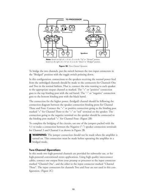
Note: Switch on left (ch. 1 & ch. 2) is in the “Up” or “Normal” position.<br />
Switch on the right (ch. 3 & ch. 4) is in the “Down” or “Bridged” position.<br />
Figure 2B Three-Channel Operation<br />
To bridge the two channels, put the switch between the two input connectors in<br />
the “Bridged” position with the toggle switch pointing down.<br />
In this configuration, connections to the speakers receiving the normal power feed<br />
from the unbridged channels should be made to the connectors for Channels One<br />
and Two in the normal fashion. That is, connect the wire running to each speaker<br />
to the appropriate output channel as marked. The “+” or “positive” connection<br />
goes to the top binding post with the red barrel. The “-” or “negative” connection<br />
goes to the bottom binding post with the black barrel.<br />
The connection for the higher power, (bridged) channel should be following the<br />
connection diagram between the speaker connection binding posts for Channel<br />
Three and Four. Connect the “+” or positive connection going to the binding post<br />
marked “+” for Channel Three to the “+” or “red” terminal on the speaker. The<br />
connection going to the negative terminal on the speaker should be connected to<br />
the binding post marked “+” for Channel Four. (Figure 2B)<br />
To complete the bridging of the circuits, use one of the jumpers packed with the<br />
<strong>5.1</strong> to make a connection between the Negative (“-”) speaker connection terminals<br />
for Channel 3 and Channel 4 as shown in Figure 2B.<br />
WARNING: The jumper connection should not be made when the amplifier is<br />
turned on. This connection must be made before operating the amplifier in a<br />
bridged mode.<br />
Two-Channel Operation:<br />
In this mode two high-powered channels are provided for subwoofer use, or for<br />
high-powered conventional stereo applications. Using high quality interconnect<br />
cables, connect one output from your preamp or processor to the input connector<br />
marked “Channel One”, and the other to the input connector marked “Channel<br />
Three”. The input connectors for channels Two and Four are not used in this configuration.<br />
(Figure 2C)<br />
15