5.1 Amplifier Owner's Manual - Harman Kardon
5.1 Amplifier Owner's Manual - Harman Kardon
5.1 Amplifier Owner's Manual - Harman Kardon

Create successful ePaper yourself
Turn your PDF publications into a flip-book with our unique Google optimized e-Paper software.
<strong>5.1</strong> <strong>Amplifier</strong> <strong>Owner's</strong> <strong>Manual</strong>
Table of Contents<br />
Important Safety Information ...............................................................................4<br />
Introduction..........................................................................................................6<br />
Description ...........................................................................................................6<br />
Unpacking and Installation ...................................................................................7<br />
Rear Panel Connections ........................................................................................8<br />
Power Control Connections ..................................................................................9<br />
Channel Configurations ......................................................................................11<br />
System Connections ............................................................................................12<br />
Input and Bridging Connections.........................................................................13<br />
Speaker Wire Preparation and Connection..........................................................17<br />
Operation............................................................................................................19<br />
Service Information.............................................................................................20<br />
Troubleshooting Guide........................................................................................21<br />
Specifications.......................................................................................................22<br />
Madrigal Audio Laboratories<br />
2081 South Main Street, P.O. Box 781<br />
Middletown, CT 06457 USA<br />
Made in USA<br />
©1995 <strong>Harman</strong> <strong>Kardon</strong>, Incorporated<br />
3
Important Safety Information<br />
Verify Line Voltage Before Use<br />
Your new Citation <strong>5.1</strong> amplifier has been factory configured for a specific line voltage:<br />
110-120 volts for North America or 220-240 volts in most other countries.<br />
Connecting the amplifier to a line voltage other than that for which it is intended<br />
can create a safety and fire hazard, and may damage the amplifier.<br />
If you have any questions about the voltage requirements for your specific model,<br />
or about the line voltage in your area, contact your Citation dealer before plugging<br />
the unit into an AC wall outlet.<br />
Verify AC Circuit Capacity Before Use<br />
High power output of your Citation amplifier requires heavy current draw under<br />
full load conditions. To insure proper performance, and to avoid potential safety<br />
hazards, we recommend that it be connected to a circuit with 20 ampere capacity.<br />
Connecting multiple amplifiers to the same circuit, or connecting it to a circuit<br />
used by other heavy power devices such as high wattage lights may cause circuit<br />
breakers to trip. It is always a good idea to avoid using any audio equipment on the<br />
same AC circuit as equipment with motors, such as air conditioners or refrigerators.<br />
This will lessen the possibility of power variation and electrical start-up noise<br />
affecting your sound system.<br />
Do Not Use Extension Cords<br />
To avoid safety hazards, use only the power cord supplied with your unit. If a replacement<br />
cord is used, make certain that it is of similar gauge. We do not recommend that<br />
extension cords be used with this product. As with all electrical devices, do not run<br />
power cords under rugs or carpets or place heavy objects on them. Damaged power<br />
cords should be replaced immediately with cords meeting factory specifications.<br />
Handle the AC Power Cord Gently<br />
When disconnecting the power cord from an AC outlet, always pull the plug, never<br />
pull the cord. If you do not intend to use the amplifier for any considerable length<br />
of time, disconnect the plug from the AC outlet.<br />
Do Not Open the Cabinet<br />
There are no user serviceable components inside this product. Opening the cabinet<br />
may present a shock hazard, and any modification to the product will void your<br />
guarantee. If water or any metal object such as a paper clip, wire or a staple accidentally<br />
falls inside the unit, disconnect it from the AC power source immediately,<br />
and consult an authorized service station.<br />
4
Installation Location<br />
• To assure proper operation, and to avoid the potential for safety hazards, place the<br />
unit on a firm and level surface. When placing the unit on a shelf, be certain that<br />
the shelf and any mounting hardware can support the amplifier. Remember, the<br />
Citation <strong>5.1</strong> weighs over 60 pounds.<br />
• High powered audio amplifiers such as the Citation <strong>5.1</strong> may develop moderate<br />
amounts of heat. Therefore, if the unit is installed in a cabinet it is recommended<br />
that the rear of the cabinet be left open to permit air circulation. If that is not<br />
possible, ventilation holes should be placed at both the top and bottom of the<br />
cabinet or enclosure, or at the sides, bottom and top. A minimum of six (6)<br />
inches should be provided between each side of the unit and the cabinet, and at<br />
least twelve (12) inches above and two (2) inches below the unit. In some cases a<br />
fan may be required to provide for air movement within a cabinet. Please consult<br />
your dealer or installer for more information.<br />
• Do not place the unit directly on a carpeted surface.<br />
• Avoid installation in extremely hot or cold locations, or in an area that is exposed<br />
to direct sunlight or heating equipment.<br />
• Avoid moist or humid locations.<br />
• Do not obstruct the ventilation slots on the top of the unit, or place objects<br />
directly over them.<br />
• Speaker wiring, input cables and power cords should be carefully placed so that<br />
they do not come in contact with, or intefere with the external heat sinks.<br />
Cleaning<br />
When the unit gets dirty, wipe it with a clean, soft, dry cloth. If necessary, first wipe<br />
the surface with a soft cloth slightly dampened with mild soapy water, then a fresh<br />
cloth with clean water. Wipe dry immediately with a dry cloth. NEVER use benzene,<br />
thinner, alcohol or any other volatile cleaning agent. Do not use abrasive cleaners, as<br />
they may damage the finish of metal parts. Avoid spraying insecticide near the unit.<br />
Moving the Unit<br />
Before moving the unit, remove any interconnect cords, and unplug it from the<br />
AC outlet.<br />
CAUTION<br />
RISK OF ELECTRIC SHOCK<br />
DO NOT OPEN<br />
CAUTION: To prevent electric shock, do not remove the grounding plug on the power cord, or use any<br />
plug or extension cord that does not have a grounding plug provided. Make certain that the AC outlet is<br />
properly grounded. Do not use an adapter plug with this product.<br />
The lightning flash with arrowhead symbol,<br />
within an equilateral triangle, is intended to<br />
alert the user to the presence of uninsulated<br />
“dangerous voltage” within the product's<br />
enclosure that may be of sufficient magnitude to constitute<br />
a risk of electric shock to persons.<br />
The exclamation point within an equilateral<br />
triangle is intended to alert the user to the<br />
presence of important operating and maintenance<br />
(servicing) instructions in the literature<br />
accompanying the appliance.<br />
5
Introduction<br />
Congratulations! As the owner of a Citation <strong>5.1</strong> Multi Channel Power<br />
<strong>Amplifier</strong>, you have at your command a unique product. The Citation <strong>5.1</strong> has been<br />
carefully designed to deliver the best possible sonic performance, along with outstanding<br />
industrial design to match the rest of the Citation series, or to complement<br />
any interior design. Combining sculpted metal panels, the latest state of the<br />
art circuit design, and <strong>Harman</strong> <strong>Kardon</strong>’s forty-year heritage of audio excellence, the<br />
Citation <strong>5.1</strong> will bring many years of enjoyable listening to your music or home<br />
theater system.<br />
In order to fully enjoy the performance of your new amplifier, please take a few<br />
minutes to read this manual. It contains important information that will help you<br />
to properly configure the amplifier for use with the rest of your audio system. The<br />
brief investment of time spent in reading this manual will yield major dividends in<br />
the form of listening enjoyment.<br />
If you have any questions about this product, its installation or operation, please<br />
contact your retailer or custom installer. They are your best source of product information.<br />
Should you need additional information or assistance, the toll-free number<br />
for the Citation Center is 800-787-6766.<br />
Welcome to the Citation family. We wish you many years of listening pleasure!<br />
<strong>5.1</strong> <strong>Amplifier</strong><br />
Description<br />
The Citation <strong>5.1</strong> is a flexible, state of the art audio power amplifier designed to<br />
deliver high performance in a variety of applications. Each of the four amplification<br />
channels has a separate power supply, which means that it delivers audiophile performance<br />
no matter which configuration is selected. You may operate the <strong>5.1</strong> in a<br />
two, three or four-channel mode, and benefit from the following array of sophisticated<br />
features:<br />
• Ultrawide bandwidth design<br />
• Low negative feedback<br />
• Fully complementary bipolar circuitry with over-designed output stage for<br />
high reliability<br />
• Low harmonic and intermodulation distortion<br />
6
• Massive heat sinks for silent convection cooling<br />
• High current power supply design with massive torrodial transformer<br />
• Quad mono power supply<br />
• New, linearized pre-driver stage circuit<br />
• Remote turn on/turn off circuitry with automatic sequencing<br />
Unpacking and Installation<br />
The carton and shipping materials used in protecting your new amplifier were specially<br />
designed to cushion it from the shocks and vibration of shipping. We suggest<br />
that you save the carton and packing materials for use in shipping if you move or<br />
should the unit ever need repair.<br />
To minimize the size of the carton in storage, you may wish to flatten it. This is<br />
done by carefully slitting the tape seams on the bottom and collapsing the carton<br />
down to a more two-dimensional appearance. Other cardboard inserts may be<br />
stored in the same manner. Packing materials that cannot be collapsed should be<br />
saved along with the carton in a plastic bag.<br />
In order to assure a high level of performance and long life, the Citation <strong>5.1</strong> has<br />
been engineered from robust materials. This weight, however, requires, that you<br />
pay special attention to unpacking and installation of the unit. First, you may wish<br />
to have someone help you remove the unit from its carton and place it in the proper<br />
location. In addition, when moving the amplifier, be careful not to set it down<br />
on the heat sink edges to avoid damage to their surface or finish. Similarly, be careful<br />
to avoid scratching any contact surface with the heat sinks, as their edges may<br />
be sharp.<br />
Make certain that any shelf or stand is capable of supporting the weight of the<br />
amplifier. This is particularly true if you will be stacking multiple amplifiers on the<br />
same shelf.<br />
When positioning the amplifier in its final location, make certain that it has adequate<br />
ventilation on all sides, as well as on the top and bottom. Do not place CDs,<br />
record jackets, owner’s manuals, or other paper, on top of, or beneath the unit, or<br />
between multiple amplifiers in a stack. This will block air flow, causing degraded<br />
performance and a possible fire hazard. If the unit is to be enclosed in a cabinet or<br />
rack, make certain that there is adequate air circulation, with a means provided for<br />
hot air to exit, and for cool air to be brought in. In some instances, a fan may be<br />
required for this purpose. If you are in doubt as to the ventilation requirements,<br />
please consult with your dealer or installer.<br />
When stacking multiple Citation <strong>5.1</strong> amplifiers in a rack or cabinet, place the unit<br />
which will power front and/or center channel speakers at the bottom of the stack.<br />
Next, place the amplifier used for surround speakers in the center. The unit which<br />
will be used to power subwoofers should be at the top of the stack.<br />
7
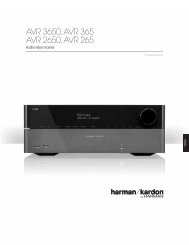
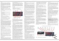
Rear Panel Connections<br />
Bridged/Normal Switches: These switches control the output configuration of a pair of channels.<br />
Switch them down for normal use. Switch them down to “bridged” to combine amplifier channels for<br />
higher power output. See page 13 for more information on channel configuration and bridging.<br />
<strong>Manual</strong>/Remote Switch: The switch controls<br />
the power turn on of the <strong>5.1</strong>. When switched up<br />
and in the “manual” position, power is turned<br />
on or off by the rear panel switch. When<br />
switched down to the “remote” position, power<br />
is controlled by signals from the Citation 7.0<br />
controller or some other device. See page 9<br />
for more information.<br />
Power Switch: This is the master AC power<br />
switch for the unit. See page 19 for more<br />
information.<br />
Remote In: This is the input jack for remote<br />
turn on control of the <strong>5.1</strong>. Connect it to a<br />
Citation Controller, and another Citation<br />
amplifier or other approved devices.<br />
See page 9 for more information.<br />
Remote Out: This is the output jack used<br />
to carry control signals for remote turn on<br />
of additional Citation amplifiers in your<br />
system. See page 9 for more information.<br />
NORMAL<br />
MODE<br />
MANUAL<br />
TURN ON<br />
NORMAL<br />
MODE<br />
OFF<br />
<strong>5.1</strong> Multi-Channel<br />
Power <strong>Amplifier</strong><br />
DESIGNED & MANUFACTURED<br />
IN THE USA.<br />
Citation,a division of<br />
<strong>Harman</strong> <strong>Kardon</strong>,<br />
Hayward, CA.<br />
+<br />
CH 1 INPUT<br />
(BRIDGED INPUT)<br />
BRIDGED<br />
MODE<br />
+ –<br />
BRIDGED<br />
CH 2 INPUT<br />
(NOT USED IN<br />
BRIDGED MODE)<br />
REMOTE<br />
TURN ON<br />
+<br />
ON<br />
DC<br />
IN<br />
DC<br />
OUT<br />
REMOTE<br />
+<br />
CH 3 INPUT<br />
(BRIDGED INPUT)<br />
BRIDGED<br />
MODE<br />
+ –<br />
BRIDGED<br />
CH 4 INPUT<br />
(NOT USED IN<br />
BRIDGED MODE)<br />
+<br />
SERIAL NUMBER<br />
–<br />
BRIDGED<br />
–<br />
120V ~ 50/60Hz<br />
1200 WATTS<br />
–<br />
BRIDGED<br />
–<br />
CH 1 OUTPUT CH 2 OUTPUT CH 3 OUTPUT CH 4 OUTPUT<br />
WHEN USING THESE CHANNELS IN BRIDGED MODE,<br />
USE THE CH 1 INPUT AND CONNECT THE SPEAKER TO<br />
THE RED TERMINALS AS DIAGRAMMED ABOVE.<br />
WHEN USING THESE CHANNELS IN BRIDGED MODE,<br />
USE THE CH 3 INPUT AND CONNECT THE SPEAKER TO<br />
THE RED TERMINALS AS DIAGRAMMED ABOVE.<br />
CAUTION<br />
RISK OF ELECTRIC SHOCK<br />
DO NOT OPEN<br />
AVIS: RISQUE DE CHOC ELECTRIQUE - NE PAS OUVRIR<br />
WARNING: TO REDUCE THE RISK OF FIRE OR<br />
ELECTRIC SHOCK DO NOT EXPOSE THIS EQUIPMENT TO<br />
RAIN OR MOISTURE. DO NOT REMOVE COVER. NO USER-<br />
SERVICEABLE PARTS INSIDE. REFER SERVICING TO<br />
QUALIFIED SERVICE PERSONNEL.<br />
Power Cord Connector:<br />
Connect the AC power cord here.<br />
Audio Input Connections: See page 13<br />
for information on proper connections<br />
and input configurations.<br />
Speaker Connection Binding Posts: Connect the<br />
wire running to your speakers to these binding posts.<br />
See page 11 for information on channel configurations<br />
connections. See page 17 for information on connecting<br />
speaker wire to the terminals.<br />
8
A division of<br />
Hayward, CA.<br />
Designed and Manufactured in the USA.<br />
L<br />
R<br />
L<br />
R<br />
AUX<br />
OUT<br />
OUT<br />
L<br />
R<br />
MAIN<br />
OUT<br />
OUT<br />
OUT<br />
OUT<br />
Manufactured under license from Dolby Laboratories Licensing Corporation. Additionally licensed under Canadian patent number 1,037,877. "Dolby", "Pro Logic" and the<br />
Double-D symbol are trademarks of Dolby Laboratories Licensing Corporation.<br />
Manufactured under license from Lucasfilm Ltd. U.S. patent numbers 5,043,970; 5,189,703; abd 5,222,059. Foreign patents pending. Lucasfilm and THX are registered<br />
trademarks of Lucasfilm Ltd.<br />
Additionally licensed under U.S. patent numbers 5,172,415; 5,263,087; 5,199,075; 5,307,415; 5,280,528; 5,339,363; 5,295,189; 4,932,059; and patents pending.<br />
IN 1 IN 2 IN 3 IN 4 AUX AUX<br />
OUT OUT OUT OUT<br />
FRONT<br />
CENTER<br />
FRONT<br />
MONO<br />
SUB<br />
SURROUNDS<br />
SIDE BACK<br />
STEREO<br />
SUB<br />
L<br />
R<br />
CALIBRATION<br />
MICROPHONE<br />
QUALIFIED SERVICE PERSONNEL.<br />
IR<br />
IN<br />
CITATION BUS<br />
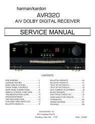
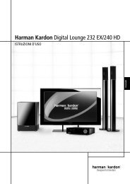
Power Control Connections<br />
The Citation <strong>5.1</strong> amplifier features a built-in system that will automatically turn<br />
on the amplifier when another device in the system is switched on. To activate this<br />
system, the <strong>5.1</strong> must be used in conjunction with a Citation Surround Controller<br />
or Processor, other Citation Power <strong>Amplifier</strong>s, and other approved devices.<br />
Remote Turn On With a Citation Controller or<br />
External Trigger Control Device<br />
The first connection is to link your amplifier to the controlling device. Connect the<br />
“PWR” Trigger output at the rear of a Citation Processor or an approved control<br />
device to the “Remote DC IN” connection on the rear panel of your <strong>5.1</strong>. Make<br />
certain that the controlling device sends a 4.5 VDC to 12 VDC signal whenever it<br />
is turned on. If you are using a Citation 7.0 Controller, be certain to use the<br />
“PWR” control trigger, not one of the numbered programmable trigger outputs.<br />
Citation 7.0 Controller<br />
7.0 AV Controller<br />
IN 1 IN 2 IN 3 IN 4<br />
POWER<br />
SERIAL<br />
NUMBER<br />
AUDIO INPUTS<br />
IN 5 IN 6 IN 7 IN 8 REC A<br />
COMPOSITE VIDEO<br />
1 2 3 4 5 6 7 8<br />
Citation <strong>5.1</strong> <strong>Amplifier</strong><br />
REC B<br />
REC A<br />
REC B<br />
AUDIO OUTPUTS<br />
REC A<br />
S – VIDEO<br />
REC B<br />
1 2 PWR<br />
TRIGGERS<br />
CAUTION<br />
RISK OF ELECTRIC SHOCK<br />
DO NOT OPEN<br />
AVIS: RISQUE DE CHOC ELECTRIQUE - NE PAS OUVRIR<br />
WARNING: TO REDUCE THE RISK OF FIRE OR<br />
ELECTRIC SHOCK DO NOT EXPOSE THIS EQUIPMENT TO<br />
RAIN OR MOISTURE. DO NOT REMOVE COVER. NO USER-<br />
SERVICEABLE PARTS INSIDE. REFER SERVICING TO<br />
120V~ 50/60Hz 50 WATTS<br />
Optional<br />
Accessory<br />
Switch<br />
Control<br />
NORMAL<br />
MANUAL<br />
MODE<br />
TURN ON<br />
BRIDGED<br />
REMOTE<br />
CH 1 INPUT<br />
MODE<br />
CH 2 INPUT TURN ON<br />
(BRIDGED INPUT) (NOT USED IN<br />
BRIDGED MODE)<br />
+ –<br />
+<br />
BRIDGED +<br />
OFF<br />
ON<br />
DC DC<br />
IN OUT<br />
REMOTE<br />
NORMAL<br />
MODE<br />
BRIDGED<br />
CH 3 INPUT<br />
MODE<br />
CH 4 INPUT<br />
(BRIDGED INPUT) (NOT USED IN<br />
BRIDGED MODE)<br />
+ –<br />
+<br />
BRIDGED +<br />
AC/DC<br />
Converter<br />
–<br />
BRIDGED<br />
–<br />
–<br />
BRIDGED<br />
–<br />
CH 1 OUTPUT<br />
CH 2 OUTPUT<br />
CH 3 OUTPUT<br />
CH 4 OUTPUT<br />
Optional Remote Trigger Devices<br />
Citation <strong>5.1</strong> <strong>Amplifier</strong><br />
NORMAL<br />
MANUAL<br />
MODE<br />
TURN ON<br />
REMOTE<br />
CH 1 INPUT BRIDGED CH 2 INPUT TURN ON<br />
(BRIDGED INPUT) MODE (NOT USED IN<br />
BRIDGED MODE)<br />
+ –<br />
+<br />
BRIDGED +<br />
–<br />
–<br />
BRIDGED<br />
CH 1 OUTPUT CH 2 OUTPUT<br />
OFF<br />
ON<br />
DC DC<br />
IN OUT<br />
REMOTE<br />
NORMAL<br />
MODE<br />
BRIDGED<br />
CH 3 INPUT<br />
MODE<br />
CH 4 INPUT<br />
(BRIDGED INPUT) (NOT USED IN<br />
BRIDGED MODE)<br />
+ –<br />
+<br />
BRIDGED +<br />
–<br />
–<br />
BRIDGED<br />
CH 3 OUTPUT CH 4 OUTPUT<br />
MANUAL<br />
TURN ON<br />
REMOTE<br />
TURN ON<br />
OFF<br />
ON<br />
DC<br />
IN<br />
DC<br />
OUT<br />
REMOTE<br />
Citation <strong>5.1</strong> <strong>Amplifier</strong><br />
NORMAL<br />
MANUAL<br />
MODE<br />
TURN ON<br />
BRIDGED<br />
REMOTE<br />
CH 1 INPUT<br />
MODE<br />
CH 2 INPUT TURN ON<br />
(BRIDGED INPUT) (NOT USED IN<br />
BRIDGED MODE)<br />
OFF<br />
ON<br />
DC DC<br />
IN OUT<br />
REMOTE<br />
NORMAL<br />
MODE<br />
BRIDGED<br />
CH 3 INPUT<br />
MODE<br />
CH 4 INPUT<br />
(BRIDGED INPUT) (NOT USED IN<br />
BRIDGED MODE)<br />
Figure 1a<br />
Exploded View of Critical<br />
Rear Panel Area<br />
+<br />
+ –<br />
BRIDGED<br />
+<br />
+<br />
+ –<br />
BRIDGED<br />
+<br />
–<br />
BRIDGED<br />
–<br />
–<br />
BRIDGED<br />
–<br />
CH 1 OUTPUT<br />
CH 2 OUTPUT<br />
CH 3 OUTPUT<br />
CH 4 OUTPUT<br />
Figure 1 Remote Turn On Connections<br />
9
If this is the only remote controlled amplifier in the system, no further connections<br />
are needed. If multiple remote controlled amplifiers are used, connect the “Remote<br />
DC OUT” jack on one amplifier to the “Remote DC IN” on the next unit in the<br />
system.<br />
Finally, make certain that the “manual/remote” switch on the rear panel is in the<br />
“remote” position to activate the remote control circuits.<br />
If the amplifier is to be controlled manually, the toggle switch should be in the<br />
“manual” position, and power will be switched on and off using the master power<br />
switch on the rear panel.<br />
Remote Turn On Using External AC to DC Power Converter<br />
If the <strong>5.1</strong> is not used with a compatible Citation Controller/Processor or other<br />
approved external device that is capable of generating turn on control voltages,<br />
it is still possible to activate the unit for automatic turn on.<br />
To control the amplifier in this fashion you will need a small AC to DC power<br />
converter, capable of delivering a 4.5 to 12 volts DC signal at 100 milliamperes.<br />
The DC voltage should terminate in a standard mini plug with the positive voltage<br />
going to the tip and the negative voltage going to the ring. This type of converter<br />
may be obtained at Radio Shack stores as catalog #273-11454.<br />
Plug the AC adapter into a switched outlet that will be activated when you wish to<br />
have the amplifier(s) turn on. This may be the switched outlet at the rear of an AC<br />
receiver or other audio equipment, an AC outlet that is part of a current sensing<br />
control unit that is activated by a preamp or surround processor, or a switched AC<br />
wall outlet.<br />
The DC output jack should be connected to the “DC IN” jack on the rear of<br />
the <strong>5.1</strong> amplifier. If there are additional amplifiers in the system, they may be<br />
connected by running a cable from the “DC OUT” jack on the first amplifier<br />
to the “DC IN” jack on the second, and so on.<br />
Before turning on the amplifiers, be certain that the “manual/remote” switch on<br />
the rear panel is in the “remote” position.<br />
The amplifiers will now turn on in sequence when power is applied to the AC outlet<br />
where the converter is plugged in. The first unit will turn on, and then each successive<br />
unit will come on following a short pause.<br />
10
Channel Configurations<br />
The Citation <strong>5.1</strong> may be used in a variety of configurations. Consult your<br />
dealer or installer for advice on which may be best for your system and listening<br />
requirements.<br />
Four-Channel Operation<br />
In multi-channel use such as a home theater system, the four channels may be<br />
allocated in a variety of ways. In some applications, they will be used to drive the<br />
left, center and right channel front speakers, with the fourth channel devoted to<br />
a subwoofer. Although you may wish to power each subwoofer with a separate,<br />
or even bridged amplifier channel, the exceptional power supply capability of<br />
the <strong>5.1</strong> will also permit you to power the three front speakers as well as a pair<br />
of subwoofers, provided that they are no less than 6 ohms each and they are<br />
connected in parallel.<br />
For systems using Citation or Fosgate•Audionics brand Dual Drive surround<br />
dipole speakers, the <strong>5.1</strong> may be used to power all four rear channels with a single<br />
amplifier.<br />
Three-Channel Operation<br />
For installations where higher power is desired for a center channel speaker, the<br />
<strong>5.1</strong> may be operated in a three-channel mode. Left and right front channel feeds<br />
are run through two unbridged channels, while the center channel is operated in<br />
a bridged mode. This allows the greater output demands of a center channel to<br />
be met, while still delivering power with headroom to spare for the left and right<br />
channels.<br />
In systems with conventional surround speakers, a three-channel application may<br />
be to feed the two rear channels in an unbridged mode, while the remaining two<br />
amplifier channels are bridged together to power a subwoofer.<br />
Two-Channel Operation<br />
The immense power capability of the Citation <strong>5.1</strong> allows it to be used in a dual<br />
bridged mode as a conventional stereo amplifier. For critical music listening, this<br />
will permit you to drive virtually any full range speaker in the largest home acoustical<br />
and physical space, delivering classic two-channel stereo sound at its finest.<br />
For home theater applications, the Citation <strong>5.1</strong> may be operated in a dual-bridged<br />
mode to power two subwoofers in large room-size installations.<br />
Caution: When used in the dual-bridged mode, the Citation <strong>5.1</strong> is capable of<br />
very high peak current outputs. Please make certain that your speakers are capable<br />
of handling this level of power before using the amplifier in this mode.<br />
11
System Connections<br />
Note: When making connections between any source components or processors<br />
or preamplifiers and the Citation <strong>5.1</strong>, or when making any connections to<br />
speakers, be certain that both the input device and the amplifier are turned off.<br />
To assure that there will be no unwanted signal transients that can damage<br />
equipment or speakers, it is always best to unplug all equipment before making<br />
any connections. Modern electronic products often have a “standby” mode that<br />
may be activated even though the product may appear to be turned off.<br />
As a general rule, avoid running any input signal or speaker wire connections in<br />
parallel with each other, or with AC power cords. This can result in undesired hum<br />
or other interference that will greatly degrade signal performance.<br />
When making connections with “RCA” type plugs on interconnect cables, make<br />
certain to gently, but firmly insert the plug into the jack on the back of the Citation<br />
<strong>5.1</strong>. Loose connections can cause intermittent sound and may damage your speakers.<br />
The barrel assembly of some high quality RCA plugs may be very tight, and it<br />
is important to assure a proper connection between the interconnection cable and<br />
the input jack.<br />
12
A division of<br />
Hayward, CA.<br />
Designed and Manufactured in the USA.<br />
L<br />
R<br />
Single Drive<br />
Dipole<br />
4Ω<br />
Dual Drive<br />
8Ω /ch.<br />
Single Drive<br />
Point Source<br />
4Ω<br />
CAUTION: Please refer to owner's manual<br />
before making any electrical connection<br />
to this speaker.<br />
L<br />
R<br />
AUX<br />
OUT<br />
OUT<br />
L<br />
R<br />
MAIN<br />
OUT<br />
OUT<br />
OUT<br />
OUT<br />
Manufactured under license from Dolby Laboratories Licensing Corporation. Additionally licensed under Canadian patent number 1,037,877. "Dolby", "Pro Logic" and the<br />
Double-D symbol are trademarks of Dolby Laboratories Licensing Corporation.<br />
Manufactured under license from Lucasfilm Ltd. U.S. patent numbers 5,043,970; 5,189,703; abd 5,222,059. Foreign patents pending. Lucasfilm and THX are registered<br />
trademarks of Lucasfilm Ltd.<br />
Additionally licensed under U.S. patent numbers 5,172,415; 5,263,087; 5,199,075; 5,307,415; 5,280,528; 5,339,363; 5,295,189; 4,932,059; and patents pending.<br />
IN 1 IN 2 IN 3 IN 4 AUX AUX<br />
OUT OUT OUT OUT<br />
FRONT<br />
CENTER<br />
FRONT<br />
MONO<br />
SUB<br />
SURROUNDS<br />
SIDE BACK<br />
STEREO<br />
SUB<br />
L<br />
R<br />
CALIBRATION<br />
MICROPHONE<br />
Single Drive<br />
Dipole<br />
4Ω<br />
QUALIFIED SERVICE PERSONNEL.<br />
IR<br />
IN<br />
Dual Drive<br />
8Ω /ch.<br />
CITATION BUS<br />
Single Drive<br />
Point Source<br />
4Ω<br />
CAUTION: Please refer to owner's manual<br />
before making any electrical connection<br />
to this speaker.<br />
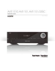
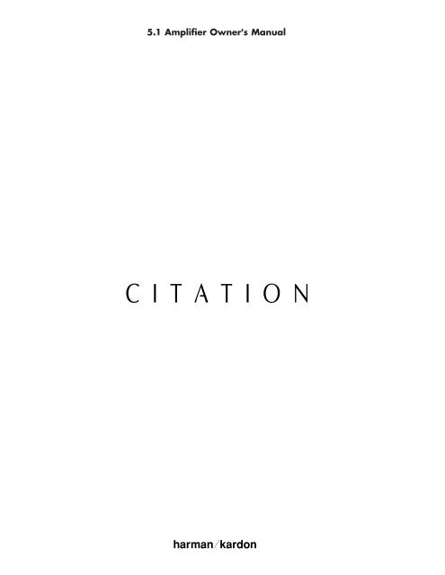
Input and Bridging Connections<br />
The RCA jacks and bridging switches on the unit’s rear panel are used to connect<br />
your surround processor or preamplifier to the amplifier, as well as to select the<br />
channel configuration. Once you have determined what the channel configuration<br />
will be, connect the output of your system to the amplifier as follows:<br />
Citation 7.0 Controller<br />
7.0 AV Controller<br />
IN 1 IN 2 IN 3 IN 4<br />
POWER<br />
SERIAL<br />
NUMBER<br />
AUDIO INPUTS<br />
IN 5 IN 6 IN 7 IN 8 REC A<br />
COMPOSITE VIDEO<br />
1 2 3 4 5 6 7 8<br />
REC B<br />
REC A<br />
REC B<br />
AUDIO OUTPUTS<br />
REC A<br />
S – VIDEO<br />
REC B<br />
CAUTION<br />
RISK OF ELECTRIC SHOCK<br />
DO NOT OPEN<br />
AVIS: RISQUE DE CHOC ELECTRIQUE - NE PAS OUVRIR<br />
WARNING: TO REDUCE THE RISK OF FIRE OR<br />
ELECTRIC SHOCK DO NOT EXPOSE THIS EQUIPMENT TO<br />
RAIN OR MOISTURE. DO NOT REMOVE COVER. NO USER-<br />
SERVICEABLE PARTS INSIDE. REFER SERVICING TO<br />
120V~ 50/60Hz 50 WATTS<br />
1 2 PWR<br />
TRIGGERS<br />
Citation <strong>5.1</strong><br />
<strong>Amplifier</strong><br />
BRIDGED<br />
REMOTE<br />
CH 1 INPUT<br />
MODE<br />
CH 2 INPUT TURN ON<br />
(BRIDGED INPUT) (NOT USED IN<br />
BRIDGED MODE)<br />
+<br />
–<br />
CH 1 OUTPUT<br />
NORMAL<br />
MODE<br />
+ –<br />
BRIDGED<br />
BRIDGED<br />
CH 2 OUTPUT<br />
+<br />
–<br />
MANUAL<br />
TURN ON<br />
OFF<br />
ON<br />
DC DC<br />
IN OUT<br />
REMOTE<br />
NORMAL<br />
MODE<br />
BRIDGED<br />
CH 3 INPUT<br />
MODE<br />
CH 4 INPUT<br />
(BRIDGED INPUT) (NOT USED IN<br />
BRIDGED MODE)<br />
+ –<br />
+<br />
BRIDGED +<br />
–<br />
–<br />
BRIDGED<br />
CH 3 OUTPUT CH 4 OUTPUT<br />
Note: Both switches<br />
should be in “Bridged”<br />
position – this is Twochannel<br />
operation mode.<br />
A jumper is used to<br />
connect both pairs of<br />
negative (“-”) terminals.<br />
Subwoofer<br />
Speakers<br />
– + – +<br />
Citation <strong>5.1</strong><br />
<strong>Amplifier</strong><br />
BRIDGED<br />
REMOTE<br />
CH 1 INPUT<br />
MODE<br />
CH 2 INPUT TURN ON<br />
(BRIDGED INPUT) (NOT USED IN<br />
BRIDGED MODE)<br />
+<br />
–<br />
CH 1 OUTPUT<br />
NORMAL<br />
MODE<br />
+ –<br />
BRIDGED<br />
BRIDGED<br />
CH 2 OUTPUT<br />
+<br />
–<br />
MANUAL<br />
TURN ON<br />
OFF<br />
ON<br />
DC DC<br />
IN OUT<br />
REMOTE<br />
NORMAL<br />
MODE<br />
BRIDGED<br />
CH 3 INPUT<br />
MODE<br />
CH 4 INPUT<br />
(BRIDGED INPUT) (NOT USED IN<br />
BRIDGED MODE)<br />
+ –<br />
+<br />
BRIDGED +<br />
–<br />
–<br />
BRIDGED<br />
CH 3 OUTPUT CH 4 OUTPUT<br />
Note: Switch between<br />
Ch. 1 & Ch. 2 should<br />
be in “Normal” position .<br />
Switch between Ch. 3<br />
& Ch. 4 is in “Bridged”<br />
position – this is Threechannel<br />
mode. A jumper<br />
is used to connect the<br />
Ch. 3 & Ch. 4 speaker<br />
negative (“-”) terminals.<br />
Front Channel<br />
Speakers<br />
– + – + – +<br />
NORMAL<br />
MANUAL<br />
MODE<br />
TURN ON<br />
BRIDGED<br />
REMOTE<br />
CH 1 INPUT<br />
MODE<br />
CH 2 INPUT TURN ON<br />
(BRIDGED INPUT) (NOT USED IN<br />
BRIDGED MODE)<br />
+ –<br />
+<br />
BRIDGED +<br />
OFF<br />
ON<br />
DC DC<br />
IN OUT<br />
REMOTE<br />
NORMAL<br />
MODE<br />
BRIDGED<br />
CH 3 INPUT<br />
MODE<br />
CH 4 INPUT<br />
(BRIDGED INPUT) (NOT USED IN<br />
BRIDGED MODE)<br />
+ –<br />
+<br />
BRIDGED +<br />
Note: Both switches<br />
should be in the “Normal”<br />
position – this is Fourchannel<br />
operation.<br />
Citation <strong>5.1</strong><br />
<strong>Amplifier</strong><br />
–<br />
CH 1 OUTPUT<br />
BRIDGED<br />
CH 2 OUTPUT<br />
–<br />
–<br />
–<br />
BRIDGED<br />
CH 3 OUTPUT CH 4 OUTPUT<br />
Single Drive/Side Input<br />
Back Input<br />
Citation<br />
Dual Drive <br />
Dipoles<br />
Single Drive/Side Input<br />
Back Input<br />
Figure 2 System Connections<br />
13
Four-Channel Operation:<br />
Using high quality interconnect cables, connect one output of your processor to an<br />
amplifier input channel. There is no special priority as to which specific channel<br />
(i.e. left, right, center, etc.) is connected to which amplifier channel when all four<br />
channels are used individually. You need only remember what the channel is, so<br />
that the proper speaker may be connected to the correct output.<br />
Make certain that both bridging switches are in the “normal” position. The toggle<br />
switches should be pointing up for both inputs.<br />
Connect the wire running to each speaker to the appropriate output channel as<br />
shown on the speaker icons to the right or left of the speaker connection binding<br />
posts. (Figure 2A) The “+” or “positive” connection goes to the top binding post<br />
with the red barrel. The “-” or “negative” connection goes to the bottom binding<br />
post with the black barrel.<br />
TO PROCESSOR<br />
NORMAL<br />
MANUAL<br />
MODE<br />
TURN ON<br />
BRIDGED<br />
REMOTE<br />
CH 1 INPUT<br />
MODE<br />
CH 2 INPUT TURN ON<br />
(BRIDGED INPUT) (NOT USED IN<br />
BRIDGED MODE)<br />
OFF<br />
ON<br />
DC DC<br />
IN OUT<br />
REMOTE<br />
NORMAL<br />
MODE<br />
BRIDGED<br />
CH 3 INPUT<br />
MODE<br />
CH 4 INPUT<br />
(BRIDGED INPUT) (NOT USED IN<br />
BRIDGED MODE)<br />
+<br />
+ –<br />
BRIDGED<br />
+<br />
+<br />
+ –<br />
BRIDGED<br />
+<br />
–<br />
BRIDGED<br />
–<br />
–<br />
BRIDGED<br />
–<br />
CH 1 OUTPUT<br />
CH 2 OUTPUT<br />
CH 3 OUTPUT<br />
CH 4 OUTPUT<br />
Single Drive/Side Input<br />
— +<br />
Back Input<br />
Note: Both<br />
Bridge/Normal<br />
switches should point<br />
Up to the “Normal”<br />
position.<br />
Single Drive/Side Input<br />
— +<br />
Back Input<br />
Figure 2A Four-Channel Operation with Dual Drive Dipoles<br />
Three-Channel Operation:<br />
When one high-powered channel and two medium-powered channels are required,<br />
the three-channel mode is used. Using high quality interconnect cables, link the<br />
output of your processor or preamplifier for the moderate powered channels<br />
(left/right front or surround channels) to the input connectors marked “Channel<br />
One” and “Channel Two”. Be certain that the bridging switch on the left side of<br />
the rear panel, above the inputs for Channel One and Channel Two, is in the<br />
“Normal” position with the toggle switch pointing up.<br />
Connect the output from your processor or preamp which is to be connected to<br />
the higher powered amplification channel (center or subwoofer channels) to the<br />
input connector marked “Channel Three” on the rear of the Citation <strong>5.1</strong>. The<br />
input connection for “Channel Four” is not used in this configuration. (Figure 2B)<br />
14
TO PROCESSOR<br />
NORMAL<br />
MANUAL<br />
MODE<br />
TURN ON<br />
BRIDGED<br />
REMOTE<br />
CH 1 INPUT<br />
MODE<br />
CH 2 INPUT TURN ON<br />
(BRIDGED INPUT) (NOT USED IN<br />
BRIDGED MODE)<br />
OFF<br />
ON<br />
DC DC<br />
IN OUT<br />
REMOTE<br />
NORMAL<br />
MODE<br />
BRIDGED<br />
CH 3 INPUT<br />
MODE<br />
CH 4 INPUT<br />
(BRIDGED INPUT) (NOT USED IN<br />
BRIDGED MODE)<br />
+<br />
+ –<br />
BRIDGED<br />
+<br />
+<br />
+ –<br />
BRIDGED<br />
+<br />
–<br />
BRIDGED<br />
–<br />
–<br />
BRIDGED<br />
–<br />
CH 1 OUTPUT<br />
CH 2 OUTPUT<br />
CH 3 OUTPUT<br />
CH 4 OUTPUT<br />
Speakers<br />
– + – + – +<br />
Note: Switch on left (ch. 1 & ch. 2) is in the “Up” or “Normal” position.<br />
Switch on the right (ch. 3 & ch. 4) is in the “Down” or “Bridged” position.<br />
Figure 2B Three-Channel Operation<br />
To bridge the two channels, put the switch between the two input connectors in<br />
the “Bridged” position with the toggle switch pointing down.<br />
In this configuration, connections to the speakers receiving the normal power feed<br />
from the unbridged channels should be made to the connectors for Channels One<br />
and Two in the normal fashion. That is, connect the wire running to each speaker<br />
to the appropriate output channel as marked. The “+” or “positive” connection<br />
goes to the top binding post with the red barrel. The “-” or “negative” connection<br />
goes to the bottom binding post with the black barrel.<br />
The connection for the higher power, (bridged) channel should be following the<br />
connection diagram between the speaker connection binding posts for Channel<br />
Three and Four. Connect the “+” or positive connection going to the binding post<br />
marked “+” for Channel Three to the “+” or “red” terminal on the speaker. The<br />
connection going to the negative terminal on the speaker should be connected to<br />
the binding post marked “+” for Channel Four. (Figure 2B)<br />
To complete the bridging of the circuits, use one of the jumpers packed with the<br />
<strong>5.1</strong> to make a connection between the Negative (“-”) speaker connection terminals<br />
for Channel 3 and Channel 4 as shown in Figure 2B.<br />
WARNING: The jumper connection should not be made when the amplifier is<br />
turned on. This connection must be made before operating the amplifier in a<br />
bridged mode.<br />
Two-Channel Operation:<br />
In this mode two high-powered channels are provided for subwoofer use, or for<br />
high-powered conventional stereo applications. Using high quality interconnect<br />
cables, connect one output from your preamp or processor to the input connector<br />
marked “Channel One”, and the other to the input connector marked “Channel<br />
Three”. The input connectors for channels Two and Four are not used in this configuration.<br />
(Figure 2C)<br />
15
TO PROCESSOR<br />
NORMAL<br />
MANUAL<br />
MODE<br />
TURN ON<br />
BRIDGED<br />
REMOTE<br />
CH 1 INPUT<br />
MODE<br />
CH 2 INPUT TURN ON<br />
(BRIDGED INPUT) (NOT USED IN<br />
BRIDGED MODE)<br />
OFF<br />
ON<br />
DC DC<br />
IN OUT<br />
REMOTE<br />
NORMAL<br />
MODE<br />
BRIDGED<br />
CH 3 INPUT<br />
MODE<br />
CH 4 INPUT<br />
(BRIDGED INPUT) (NOT USED IN<br />
BRIDGED MODE)<br />
+<br />
+ –<br />
BRIDGED<br />
+<br />
+<br />
+ –<br />
BRIDGED<br />
+<br />
–<br />
BRIDGED<br />
–<br />
–<br />
BRIDGED<br />
–<br />
CH 1 OUTPUT<br />
CH 2 OUTPUT<br />
CH 3 OUTPUT<br />
CH 4 OUTPUT<br />
– +<br />
Speakers<br />
– +<br />
Note: Both switches should point Down to the “Bridged” position.<br />
Figure 2C Two-Channel Operation<br />
For two-channel use, make certain that BOTH bridging switches are engaged by<br />
switching them down, to the “bridged” position.<br />
In the bridged mode, the connections to your speakers should be made using only<br />
the top row of binding post connections. Follow the connection diagram that is<br />
between the speaker connections. For the speaker connected to the Channel One<br />
input, connect the “+” terminal of the Channel One output to the wire going<br />
to the “+” or red colored connection on your speaker. Connect the “+” terminal<br />
of the Channel Two output to the wire going to the “-” or black terminal of<br />
your speaker.<br />
Repeat this procedure so that the input signal connected to the Channel Three<br />
input connector is connected to your speaker using the “+” speaker output connector<br />
of Channel Three as the “+” or “red” wire, and the “+” speaker output<br />
connector of Channel Four as the “-” or “black” wire.<br />
To complete the bridging of the circuits, use the jumpers packed with the <strong>5.1</strong> to<br />
make a connection between the Negative (“-”) speaker connection terminals for<br />
Channel 1/Channel 2, and Channel 3/Channel 4 as shown in Figure 2C.<br />
WARNING: The jumper connections should not be made when the amplifier<br />
is turned on. This connection must be made before operating the amplifier in<br />
a bridged mode.<br />
Note: When using the <strong>5.1</strong> in a dual-bridged configuration, particularly with<br />
4 ohm speaker loads, it will probably be necessary to provide additional cooling<br />
using a small fan. This cooling will also be needed in the dual-bridged mode if<br />
the amplifier is enclosed in a cabinet. Consult your dealer or custom installer for<br />
more information.<br />
16
Speaker Wire Preparation and Connection<br />
Once the proper hookup has been selected using the previous section, make the<br />
physical connection using the following instructions.<br />
Cables or Connecting Wire<br />
To assure that the high quality signals produced by your Citation amplifier are carried<br />
to your speakers without loss of clarity or resolution, we recommend that you<br />
use high quality speaker cable. Many brands of cable are available, and the choice<br />
of cable may be influenced by the distance between your speakers and the amplifier,<br />
the type of speakers you use, personal preferences, and other factors. Your dealer<br />
or installer is a valuable resource to consult in selecting the proper cable for<br />
connections between your amplifier and speakers.<br />
Regardless of the brand or type of cable selected, we recommend that you use a<br />
cable constructed of fine, multi-strand copper with a AWG of 14 or larger.<br />
Remember, that in specifying cable, the lower the number, the thicker the cable.<br />
Cable with an AWG of 16 may be used for short runs of less than ten feet. We do<br />
not recommend that you use any cables with an AWG equivalent of 18 or higher<br />
due to the power loss and degradation in performance that will occur.<br />
One way to insure that cables will deliver a predictable level of performance is to<br />
use cables that are Home THX ® certified. This certification assures that the cables<br />
have met a rigorous set of specifications designed for home theater applications.<br />
Cables that are run inside walls should have the appropriate markings to indicate<br />
listing with UL, CSA or other testing agency standards. Questions about cables<br />
inside walls should be referred to your installer or a licensed electrical contractor<br />
who is familiar with the NEC and/or the applicable local building codes in<br />
your area.<br />
Connections to Speakers<br />
Regardless of the channel configuration used, the final step of the installation<br />
process is to connect the amplifier to your speakers, using high quality cable, as<br />
outlined above. A pair of binding posts is provided for each channel output. These<br />
posts will accept bare wire, spade lugs or banana-type plugs where permitted by<br />
local safety agencies.<br />
If bare wire is used for the connections, strip approximately 1/2 inch to 3/4 inch<br />
(20mm) of insulation from the end of each wire and carefully twist the strands of<br />
each conductor together. Be careful not to cut the individual strands or twist them<br />
off; for optimal performance, all strands must be used.<br />
Then, loosen the knobs of the speaker output terminals, far enough so that the<br />
pass-through hole is revealed. Note that one conductor of the speaker cable may<br />
have no markings, and the other will have a red line, brand name markings, a black<br />
thread, or some other positive indication. Follow the proper connection instructions<br />
for your system with regard to which terminals are used. The small speaker<br />
17
icons next to each pair of terminal posts will guide you to the correct connections.<br />
When the connections are made, twist the cap back so that the connection is<br />
secured, but do not overtighten or use tools, as this may break the delicate wire<br />
strands and decrease system performance. Also, make certain that the wire strands<br />
connected to one terminal do not contact the other terminal or wires. This will<br />
result in a short circuit.<br />
If you are using spade lugs, connect them to the wire using the manufacturer’s<br />
instructions, and then loosen the caps on the speaker terminals. Place lugs between<br />
the plastic cap and the back of the terminal, as if it were a horseshoe on the game’s<br />
post. Be sure to observe proper polarity, using the appropriate speaker hookup<br />
icons for your system’s configuration. Tighten with your fingers to obtain a<br />
positive contact.<br />
When banana plugs are permitted, connections may be made by simply inserting<br />
the jack affixed to your speaker wire into the hole provided on the rear of the colored<br />
screw caps on the binding posts. Before using banana-type jacks, make certain<br />
that the plastic screw caps are firmly tightened down by turning them in a counterclockwise<br />
direction until they are snug against the chassis. This will insure that the<br />
maximum surface area of the plug is in contact with the jack. Be certain to observe<br />
proper polarity.<br />
Finally, run the cables to the speaker locations. It is highly recommended that the<br />
length of cable connecting any pair of speakers is identical. For example, make certain<br />
that the cable length connecting left and right front, or left and right rear (surround)<br />
speakers are identical, even though one speaker may be physically closer to<br />
the amplifier than the other. Do not coil any excess cable, as this may become an<br />
inductor that creates frequency response variations in your system.<br />
Finally, connect the wires to the speakers, again being certain to observe proper<br />
polarity. Remember to connect your “negative” or “black” wire to the matching terminal<br />
on the speaker. Similarly, the “positive” or “Red” wire should be connected<br />
to the like terminal on the speaker.<br />
Note: While most speaker manufacturers adhere to an industry convention of<br />
using black terminals for negative and red ones for positive, some manufacturers<br />
may vary from this configuration. To assure proper phase connections, and optimal<br />
performance, consult the identification plate on your speaker terminals, or<br />
the speaker’s manual to verify polarity. If you do not know the polarity of your<br />
speaker, ask your dealer or installer for advice before proceeding, or consult the<br />
speaker’s manufacturer.<br />
18
Operation<br />
Operation of the Citation <strong>5.1</strong> is simple. There are no controls to adjust once the<br />
installation is complete.<br />
After all connections have been made to the amplifier’s inputs and speaker terminals,<br />
connect the AC power cord to the socket on the rear panel. Make certain that<br />
the master power switch on the rear panel is in the OFF position. Connect the<br />
power cord to an AC outlet.<br />
Note that it is not recommended that you connect multiple <strong>5.1</strong> <strong>Amplifier</strong>s to the<br />
same AC power circuit unless they are used with the remote power turn on and<br />
sequencing system. The simultaneous turn on of multiple amplifiers on the same<br />
circuit may cause circuit breakers to trip.<br />
Note: Do not attempt to defeat the grounding plug on the power cord. This<br />
will cause a safety hazard. It will also increase the chance of unwanted hum<br />
appearing in your system. If a properly grounded AC outlet is not available,<br />
contact your installer or a licensed electrician for assistance.<br />
At this point you are ready for listening: First, turn on the source components and<br />
processor in your system. It is always a good idea to turn on your amplifier LAST.<br />
This avoids the possibility of any turn on pops or transients from other equipment<br />
being amplified and sent to your speakers where they may cause damage. Always<br />
start with a low volume level on your controller or preamp to avoid damage to your<br />
speakers.<br />
For <strong>Manual</strong> Operation:<br />
If the unit is not being used with the automatic, remote turn on system, place the<br />
“manual/remote” toggle switch in the “manual” position. Switch the rear panel<br />
master power switch to the ON position. The LED below the Citation name on<br />
the front panel will illuminate and turn blue to let you know that power is applied.<br />
There will be a short pause between the time the power is turned on until power<br />
is applied to the speakers. This is intentional, and it protects your speakers from<br />
damage as the amplifier stabilizes. You may also hear a relay click as during<br />
start-up. This is also normal.<br />
You are now ready to enjoy the finest sonic performance available. All volume and<br />
level adjustments are made at your preamp, controller or surround processor.<br />
To turn the unit off, switch the rear panel master power switch to the OFF<br />
position.<br />
19
For Automatic Operation:<br />
Make certain that all connections to the Citation Controller or Processor, and to<br />
any other Citation power amplifiers in the system have been correctly made as<br />
shown on pages 13 through 16. Switch the “manual/remote” toggle switch on the<br />
rear panel to the “remote” position. Turn the master power switch ON, position.<br />
The LED below the Citation name will turn amber to indicate that the unit is in<br />
the “standby” mode with AC power applied.<br />
Your Citation <strong>5.1</strong> amplifier will now turn on automatically whenever the processor or<br />
controller is switched on. You may verify that your amplifier has been turned on in<br />
response to the control signal by noting that the LED below the Citation name will<br />
change from amber to blue. There will be a short second pause between the time the<br />
signal is applied and the indicator changes color until power is applied to the speakers.<br />
This pause is intentional, and it protects your speakers from damage as the amplifier<br />
stabilizes. You may also hear a relay click as during start-up. This is also normal.<br />
Once your system is turned on, you are ready to enjoy the finest sonic performance<br />
available. There are no controls to adjust on the Citation <strong>5.1</strong> amplifier. All volume<br />
and level adjustments are made by your preamp, controller or surround processor.<br />
There is no need to turn the amplifiers off manually. Simply turn off the Citation<br />
Controller or Processor, or the device providing the automatic control voltages and<br />
the <strong>5.1</strong> amplifier will go into a standby mode. Turn off and return to a standby<br />
mode may be confirmed by noting that the LED indicator under the Citation<br />
name on the front panel turns from blue to amber.<br />
Important Note: If you will not be using your audio system for an extended<br />
period of time, such as a vacation, it is always a good idea to turn the unit off<br />
using the rear panel power switch. This will prevent the automatic turn on circuits<br />
from accidentally turning the system on during your absence.<br />
Service Information<br />
If your installation has followed the suggestions in this manual you should enjoy<br />
many years of trouble-free operation and high quality listening enjoyment. If you<br />
suspect a problem that may require service assistance, contact your dealer, installer<br />
or an authorized Citation Service Depot. The Citation <strong>5.1</strong> does not contain any<br />
user serviceable parts. In the event of a problem, contact your dealer, custom<br />
installer or Madrigal Technical Services at 888-691-4171 (USA Only).<br />
It is important that any repairs be carried out only by an authorized Citation service<br />
agent to assure proper service and to preserve the protection of your Limited<br />
Warranty. It is a good idea to keep your sales slip or receipt in a safe place with this<br />
manual so that it will be available to verify the purchase date for warranty claims.<br />
Fuse<br />
The Citation <strong>5.1</strong> uses internal fuses to protect both it and your speakers from damage.<br />
In the event that a fuse replacement is required, make certain that a fuse of the<br />
original rating is used. Contact an authorized Citation service agent for assistance<br />
with fuse replacement.<br />
20
Input/Output Protection<br />
Under some conditions, such as a shorted speaker wire, DC voltage on an input<br />
connection or thermal overload, the Citation <strong>5.1</strong> will place itself in a “protect”<br />
mode to prevent damage to your speakers. When this happens the power indicator<br />
will turn red and no signal will be heard. You may hear a relay “click” on as the<br />
unit goes into its protection mode.<br />
When this occurs, turn the unit off using the rear panel switch, and correct the<br />
problem. Turn the unit back on. If the unit continues to go into a protect mode,<br />
contact your dealer or installer for assistance.<br />
Troubleshooting Guide<br />
The Citation <strong>5.1</strong> is designed for trouble free operation. In normal use, most users<br />
will not encounter any problems with the unit. However, as with any sophisticated<br />
electronic device, there may be occasional problems on initial installation, or<br />
during the life of the unit. The items on this list are a brief guide to the minor<br />
problems that you may be able to correct yourself. If these solutions do not rectify<br />
a problem, or if the problem persists, contact your dealer, installer or an authorized<br />
Citation service center for assistance.<br />
Problem Diagnosis Troubleshooting Hints Page<br />
<strong>Amplifier</strong> will not turn on. Master Power Switch Turned Turn on Master Power 8, 19<br />
Off. (No Power Light LED) Switch.<br />
Make certain power cord 8<br />
is firmly inserted into<br />
receptacle.<br />
Remote turn-on system not Check all connections and 8, 9<br />
properly configured. switch settings for remote<br />
(Power Light LED is amber) system.<br />
Check External Trigger 9<br />
Device.<br />
<strong>Amplifier</strong> turns on, but Inputs not connected to Check Input Connections. 11-16<br />
no audio from one or proper jack.<br />
more channels.<br />
Speakers not connected Check Speaker Connections. 13-18<br />
properly.<br />
Improper settings or output Check the settings on your Consult the<br />
levels from the processor or preamp, processor or manual for<br />
controller. controller. the source<br />
device.<br />
Audio plays, then cuts off. <strong>Amplifier</strong> Shorted Check Speaker connections 13-18<br />
(LED is red)<br />
for short circuit.<br />
21
Specifications<br />
Power Output:<br />
HCC:<br />
Frequency Response:<br />
THD/IMD:<br />
Power Bandwidth:<br />
Input Impedance:<br />
Input Sensitivity:<br />
Control Trigger Voltage:<br />
Dimensions (HxWxD):<br />
Weight:<br />
Power Requirements:<br />
4 x 100 watts @ 8 ohms, 4 x 175 watts @ 4 ohms<br />
2 x 100 watts + 1 x 300 watts @ 8 ohms,<br />
2 x 300 watts @ 8 ohms bridged<br />
FTC: 20 - 20 kHz, .03% THD, All channels driven<br />
100 Amps/channel in dual mono mode<br />
Staple or clip original invoice here. ▼
Madrigal Audio Laboratories<br />
2081 South Main Street, P.O. Box 871<br />
Middletown, CT 06457 USA<br />
Telephone: 860.346.0896<br />
Fax: 860.346.1540<br />
Part No. CIT<strong>5.1</strong>OM