tec.News - Harting
tec.News - Harting
tec.News - Harting

You also want an ePaper? Increase the reach of your titles
YUMPU automatically turns print PDFs into web optimized ePapers that Google loves.
PHYSICAL LAYER SPECIFICA-<br />
TION PICMG 2.5<br />
Since the PICMG is responsible for<br />
all CPCI-relevant specifications,<br />
the H.110 recommendations of the<br />
ECTF were integrated into the<br />
Computer Telephony Specification<br />
PICMG 2.5.<br />
The 6SU standard board for computer<br />
telephony on the Compact-<br />
PCI bus contains the following<br />
connectors:<br />
• P1/J1 carries the 32-bit PCI bus<br />
(the connector is Type A in compliance<br />
with IEC 61076-101)<br />
• P2/J2 contains the other connections<br />
for the 64-bit PCI bus<br />
(the connector is based on IEC<br />
Type B, but in a shorter version)<br />
• P3/J3 is not defined for CPCI-CT<br />
but can be used for additional<br />
input and output signals<br />
• P4/J4 carries the CT bus to H.110<br />
(the connector is IEC Type A)<br />
• P5/J5 is reserved for input and<br />
output signals to other equipment<br />
in the network, which are<br />
fed from the rear of the equipment<br />
to the bus (the connector<br />
is based on IEC Type B, but in a<br />
shorter version)<br />
SPECIAL CHARACTERISTICS<br />
OF CONNECTORS AND<br />
MODULAR SYSTEM<br />
CT rack cards can be positioned directly<br />
next to other rack cards in<br />
the modular system. Coding elements<br />
at P4/J4 ensure correct positioning.<br />
For easier recognition, a colour coding<br />
has been introduced in addition<br />
to the physical contour: strawberry<br />
red is defined for CT rack cards.<br />
The input and output signals at position<br />
P5/J5 can be fed via 80 millimetre<br />
deep rear I/O transition boards<br />
in compliance with IEEE P1101.11.<br />
This permits a very compact housing<br />
design with continuous screening of<br />
the housing. With the aid of the I/O<br />
transition boards, line terminations<br />
and circuits can, for example, be integrated<br />
for preparation of the incoming<br />
and outgoing signals, or the<br />
cable connectors can be simply<br />
adapted to customer requirements.<br />
The signal connection from the I/O<br />
transition boards to the CT backplane<br />
is via har-bus ® HM female<br />
connectors and a guide shroud,<br />
which is pushed onto the rear long<br />
connection posts of the J5 connector.<br />
To guide and centre the male<br />
and female connectors in relation to<br />
each other, a type complementary<br />
to the standard, bearing the type<br />
designation AB, is used at this point.<br />
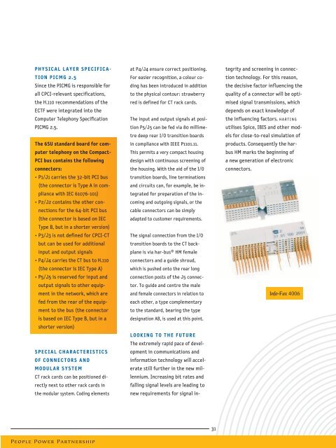
LOOKING TO THE FUTURE<br />
The extremely rapid pace of development<br />
in communications and<br />
information <strong>tec</strong>hnology will accelerate<br />
still further in the new millennium.<br />
Increasing bit rates and<br />
falling signal levels are leading to<br />
new requirements for signal integrity<br />
and screening in connection<br />
<strong>tec</strong>hnology. For this reason,<br />
the decisive factor influencing the<br />
quality of a connector will be optimised<br />
signal transmissions, which<br />
depends on exact knowledge of<br />
the influencing factors. HARTING<br />
utilises Spice, IBIS and other models<br />
for close-to-real simulation of<br />
products. Consequently the harbus<br />
HM marks the beginning of<br />
a new generation of electronic<br />
connectors.<br />
Info-Fax 4006<br />
31<br />
People Power Partnership