

STR-W6753
STR-W6753
STR-W6753

You also want an ePaper? Increase the reach of your titles
YUMPU automatically turns print PDFs into web optimized ePapers that Google loves.
Switching<br />
Regulators<br />
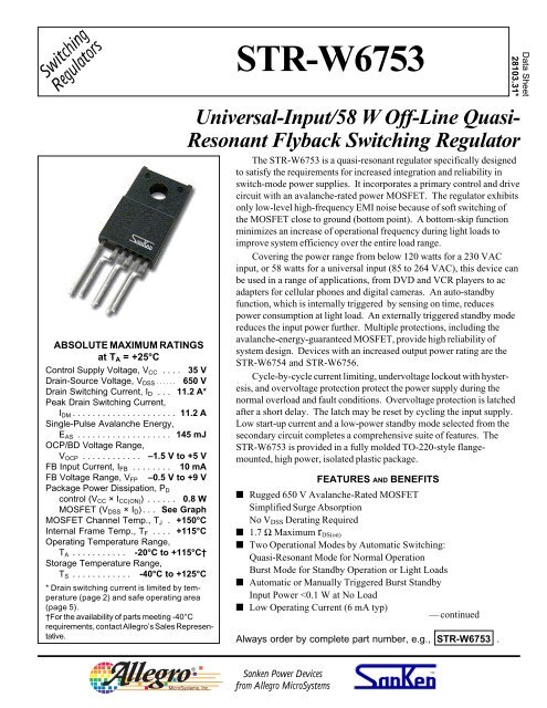
ABSOLUTE MAXIMUM RATINGS<br />
at T A = +25°C<br />
Control Supply Voltage, V CC . . . . 35 V<br />
Drain-Source Voltage, V DSS . . . . . . 650 V<br />
Drain Switching Current, I D . . . 11.2 A*<br />
Peak Drain Switching Current,<br />
I DM . . . . . . . . . . . . . . . . . . . . . 11.2 A<br />
Single-Pulse Avalanche Energy,<br />
E AS . . . . . . . . . . . . . . . . . . . 145 mJ<br />
OCP/BD Voltage Range,<br />
V OCP . . . . . . . . . . . . –1.5 V to +5 V<br />
FB Input Current, I FB . . . . . . . . 10 mA<br />
FB Voltage Range, V FP –0.5 V to +9 V<br />
Package Power Dissipation, P D<br />
control (V CC × I CC(ON) ) . . . . . . 0.8 W<br />
MOSFET (V DSS × I D ). . . See Graph<br />
MOSFET Channel Temp., T J . +150°C<br />
Internal Frame Temp., T F . . . . +115°C<br />
Operating Temperature Range,<br />
T A . . . . . . . . . . . -20°C to +115°C†<br />
Storage Temperature Range,<br />
T S . . . . . . . . . . . . -40°C to +125°C<br />
* Drain switching current is limited by temperature<br />
(page 2) and safe operating area<br />
(page 5).<br />
†For the availability of parts meeting -40°C<br />
requirements, contact Allegro’s Sales Representative.<br />
<strong>STR</strong>-<strong>W6753</strong><br />
Universal-Input/58 W Off-Line Quasi-<br />
Resonant Flyback Switching Regulator<br />
The <strong>STR</strong>-<strong>W6753</strong> is a quasi-resonant regulator specifically designed<br />
to satisfy the requirements for increased integration and reliability in<br />
switch-mode power supplies. It incorporates a primary control and drive<br />
circuit with an avalanche-rated power MOSFET. The regulator exhibits<br />
only low-level high-frequency EMI noise because of soft switching of<br />
the MOSFET close to ground (bottom point). A bottom-skip function<br />
minimizes an increase of operational frequency during light loads to<br />
improve system efficiency over the entire load range.<br />
Covering the power range from below 120 watts for a 230 VAC<br />
input, or 58 watts for a universal input (85 to 264 VAC), this device can<br />
be used in a range of applications, from DVD and VCR players to ac<br />
adapters for cellular phones and digital cameras. An auto-standby<br />
function, which is internally triggered by sensing on time, reduces<br />
power consumption at light load. An externally triggered standby mode<br />
reduces the input power further. Multiple protections, including the<br />
avalanche-energy-guaranteed MOSFET, provide high reliability of<br />
system design. Devices with an increased output power rating are the<br />
<strong>STR</strong>-W6754 and <strong>STR</strong>-W6756.<br />
Cycle-by-cycle current limiting, undervoltage lockout with hysteresis,<br />
and overvoltage protection protect the power supply during the<br />
normal overload and fault conditions. Overvoltage protection is latched<br />
after a short delay. The latch may be reset by cycling the input supply.<br />
Low start-up current and a low-power standby mode selected from the<br />
secondary circuit completes a comprehensive suite of features. The<br />
<strong>STR</strong>-<strong>W6753</strong> is provided in a fully molded TO-220-style flangemounted,<br />
high power, isolated plastic package.<br />
FEATURES AND BENEFITS<br />
■ Rugged 650 V Avalanche-Rated MOSFET<br />
Simplified Surge Absorption<br />
No V DSS Derating Required<br />
■ 1.7 Ω Maximum r DS(on)<br />
■ Two Operational Modes by Automatic Switching:<br />
Quasi-Resonant Mode for Normal Operation<br />
Burst Mode for Standby Operation or Light Loads<br />
■ Automatic or Manually Triggered Burst Standby<br />
Input Power
<strong>STR</strong>-<strong>W6753</strong><br />
Universal-Input/58 W Off-Line Quasi-<br />
Resonant Flyback Switching Regulator<br />
Switching<br />
Regulators<br />
FUNCTIONAL BLOCK DIAGRAM<br />
FEATURES AND BENEFITS (cont’d)<br />
■ Auto-Bias Function<br />
Stable Burst Operation Without Generating Interference<br />
■ Internal Off-Timer Circuit<br />
■ Built-In Constant-Voltage Drive<br />
■ Multiple Protections:<br />
Pulse-by-Pulse Overcurrent Protection<br />
Overload Protection with Auto Recovery<br />
Latching Overvoltage Protection<br />
Undervoltage Lockout with Hysteresis<br />
■ RoHS Compliant<br />
2<br />
115 Northeast Cutoff, Box 15036<br />
Worcester, Massachusetts 01615-0036<br />
Copyright © 2005 Allegro MicroSystems, Inc.
Switching<br />
Regulators<br />
<strong>STR</strong>-<strong>W6753</strong><br />
Universal-Input/58 W Off-Line Quasi-<br />
Resonant Flyback Switching Regulator<br />
ELECTRICAL CHARACTERISTICS at T A = +25°C, V CC = 20 V, voltage measurements are referenced to S/GND terminal<br />
(unless otherwise specified).<br />
Limits<br />
Characteristic Symbol Test Conditions Min. Typ. Max. Units<br />
Start-Up Operation<br />
Operation Start Voltage V CC(ON) Turn-on, V CC = 0 19.9 V 16.3 18.2 19.9 V<br />
Soft-Start Operation Stop Voltage V SS/OLP 1.1 1.2 1.4 V<br />
Soft-Start Oper. Charging Current I SS/OLP -390 -550 -710 µA<br />
Operation Stop Voltage V CC(OFF) Turn-off, V CC = 19.9 8.8 V 8.8 9.7 10.6 V<br />
Circuit Current in Non-Operation I CC(OFF) V CC = 15 V – – 100 µA<br />
Normal Operation<br />
Drain-Source Breakdown Voltage V (BR)DSS I D = 300 µA 650 – – V<br />
Drain Leakage Current I DSS V DS = 650 V – – 300 µA<br />
On-State Resistance r DS(on) I D = 1.4 A, T J = +25°C – – 1.7 Ω<br />
Switching Time t f – – 400 ns<br />
Circuit Current I CC(ON) – – 6.0 mA<br />
Oscillation Frequency f osc 19 22 25 kHz<br />
Bottom-Skip Oper. Threshold Volt. V OCPBD(BS1) -605 -665 -720 mV<br />
V OCPBD(BS2) -385 -435 -485 mV<br />
Quasi-Resonant Oper. Threshold V OCPBD(TH1) 280 400 520 mV<br />
V OCPBD(TH2) 670 800 930 mV<br />
Feedback-Pin Threshold Voltage V FB(OFF) 1.32 1.45 1.58 V<br />
Feedback-Pin Current I FB(ON) 600 1000 1400 µA<br />
Standby Operation<br />
Standby Operation Start Voltage V CC(S) V CC = 0 12.2 V 10.3 11.1 12.1 V<br />
Standby Oper. Start Volt. Interval V CC 1.10 1.35 1.65 V<br />
Standby Non-Operation Current I CC(S) V CC = 10.2 V – 20 56 µA<br />
Feedback-Pin Current I FB(ON) V CC = 10.2 V – 4.0 14 µA<br />
Feedback-Pin Threshold Voltage V FB(S) V CC = 12.2 V 0.55 1.10 1.50 V<br />
Minimum ON Time t on(min) 0.5 0.8 1.2 µs<br />
continued next page ...<br />
www.allegromicro.com 3
<strong>STR</strong>-<strong>W6753</strong><br />
Universal-Input/58 W Off-Line Quasi-<br />
Resonant Flyback Switching Regulator<br />
Switching<br />
Regulators<br />
ELECTRICAL CHARACTERISTICS at T A = +25°C, V CC = 20 V, voltage measurements are referenced to S/GND terminal<br />
(unless otherwise specified).<br />
Protection Operation<br />
OVP Operation Voltage V CC(OVP) Turn-off, V CC = 0 29.9 V 25.5 27.7 29.9 V<br />
Maximum ON Time t on(max) 27.5 32.5 39.0 µs<br />
OLP Operation Voltage V SSOLP 4.0 4.9 5.8 V<br />
OLP Operation Current I SSOLP -6.0 -11 -16 µA<br />
Overcurrent Detect. Threshold Volt. V OCPBD(LIM) -0.895 -0.940 -0.995 V<br />
OCP/BD-Pin Current I OCPBD -40 -100 -250 µA<br />
Latch Holding Current I CC(H) V CC = 29.9 V CC(OFF) – 0.3 V – 45 140 mA<br />
Latch Release Voltage V CC(L) V CC = 29.9 6 V 6.0 7.2 8.5 V<br />
Other<br />
Thermal Resistance R θJF Output junction-to-frame – – 2.0 °C/W<br />
NOTES: 1. Typical Data is for design information only.<br />
2. Negative current is defined as coming out of (sourcing) the specified device termninal.<br />
Limits<br />
Characteristic Symbol Test Conditions Min. Typ. Max. Units<br />
4<br />
115 Northeast Cutoff, Box 15036<br />
Worcester, Massachusetts 01615-0036
Switching<br />
Regulators<br />
<strong>STR</strong>-<strong>W6753</strong><br />
Universal-Input/58 W Off-Line Quasi-<br />
Resonant Flyback Switching Regulator<br />
MOSFET TYPICAL CHARACTERISTICS<br />
Avalanche energy is measured at V DD = 99 V,<br />
L = 20 mH, I L = 3.6 A.<br />
www.allegromicro.com 5
<strong>STR</strong>-<strong>W6753</strong><br />
Universal-Input/58 W Off-Line Quasi-<br />
Resonant Flyback Switching Regulator<br />
Switching<br />
Regulators<br />
MOSFET TYPICAL CHARACTERISTICS (cont’d)<br />
WARNING — These devices are designed to be operated at lethal voltages and energy levels. Circuit designs<br />
that embody these components must conform with applicable safety requirements. Precautions must<br />
be taken to prevent accidental contact with power-line potentials. Do not connect grounded test<br />
equipment.<br />
The use of an isolation transformer is recommended during circuit development and breadboarding.<br />
6<br />
115 Northeast Cutoff, Box 15036<br />
Worcester, Massachusetts 01615-0036
Switching<br />
Regulators<br />
<strong>STR</strong>-<strong>W6753</strong><br />
Universal-Input/58 W Off-Line Quasi-<br />
Resonant Flyback Switching Regulator<br />
APPLICATIONS INFORMATION<br />
Typical Application<br />
Complete product description and applications information<br />
is provided in Application Note 28103.30, Series <strong>STR</strong>-<br />
W6750 Off-Line Quasi-Resonant Flyback Switching<br />
Regulators.<br />
The products described herein are manufactured in Japan by Sanken<br />
Electric Co., Ltd. for sale by Allegro MicroSystems, Inc.<br />
Sanken and Allegro reserve the right to make, from time to time, such<br />
departures from the detail specifications as may be required to permit<br />
improvements in the performance, reliability, or manufacturability of its<br />
products. Therefore, the user is cautioned to verify that the information<br />
in this publication is current before placing any order.<br />
When using the products described herein, the applicability and<br />
suitability of such products for the intended purpose shall be reviewed at<br />
the users responsibility.<br />
Although Sanken undertakes to enhance the quality and reliability of<br />
its products, the occurrence of failure and defect of semiconductor<br />
products at a certain rate is inevitable.<br />
Users of Sanken products are requested to take, at their own risk,<br />
preventative measures including safety design of the equipment or<br />
systems against any possible injury, death, fires or damages to society<br />
due to device failure or malfunction.<br />
Sanken products listed in this publication are designed and intended<br />
for use as components in general-purpose electronic equipment or<br />
apparatus (home appliances, office equipment, telecommunication<br />
equipment, measuring equipment, etc.). Their use in any application<br />
requiring radiation hardness assurance (e.g., aerospace equipment) is<br />
not supported.<br />
When considering the use of Sanken products in applications where<br />
higher reliability is required (transportation equipment and its control<br />
systems or equipment, fire- or burglar-alarm systems, various safety<br />
devices, etc.), contact a company sales representative to discuss and<br />
obtain written confirmation of your specifications.<br />
The use of Sanken products without the written consent of Sanken in<br />
applications where extremely high reliability is required (aerospace<br />
equipment, nuclear power-control stations, life-support systems, etc.) is<br />
strictly prohibited.<br />
The information included herein is believed to be accurate and<br />
reliable. Application and operation examples described in this publication<br />
are given for reference only and Sanken and Allegro assume no<br />
responsibility for any infringement of industrial property rights,<br />
intellectual property rights, or any other rights of Sanken or Allegro or<br />
any third party that may result from its use.<br />
EI16EI<br />
www.allegromicro.com 7
<strong>STR</strong>-<strong>W6753</strong><br />
Universal-Input/58 W Off-Line Quasi-<br />
Resonant Flyback Switching Regulator<br />
Switching<br />
Regulators<br />
PACKAGE DIMENSIONS<br />
in Millimeters<br />
Product weight: approx. 2.3 g.<br />
Recommended mounting hardware torque: 0.588 ~ 0.785 Nm, 6 ~ 8 kgf × cm.<br />
Recommended silicon grease: Dow Corning SC102, Toshiba YG6260, Shin-Etsu G746, or equivalent.<br />
8<br />
115 Northeast Cutoff, Box 15036<br />
Worcester, Massachusetts 01615-0036


