Finding the Lumped Element Varactor Diode Model
Finding the Lumped Element Varactor Diode Model
Finding the Lumped Element Varactor Diode Model

You also want an ePaper? Increase the reach of your titles
YUMPU automatically turns print PDFs into web optimized ePapers that Google loves.
High Frequency Design<br />
VARACTOR MODEL<br />
From November 2003 High Frequency Electronics<br />
Copyright © 2003 Summit Technical Media, LLC<br />
<strong>Finding</strong> <strong>the</strong> <strong>Lumped</strong> <strong>Element</strong><br />
<strong>Varactor</strong> <strong>Diode</strong> <strong>Model</strong><br />
By George H. Stauffer<br />
Rockwell Collins<br />
Here is a method for<br />
using measured data to<br />
accurately describe <strong>the</strong><br />
behavior of a varactor<br />
diode, providing <strong>the</strong> CAD<br />
simulator with a model that<br />
corresponds to actual<br />
device performance<br />
An accurate model<br />
for <strong>the</strong> varactor<br />
diode is necessary<br />
when designing a voltage<br />
controlled oscillator<br />
(VCO) using CAD simulation.<br />
In order to predict<br />
tuning range, start up<br />
gain, and phase noise, <strong>the</strong><br />
resonator must be accurately<br />
modeled over <strong>the</strong> frequency range of <strong>the</strong><br />
oscillations. The varactor diode used for tuning<br />
has a predominant effect on <strong>the</strong> Q, phase<br />
noise and tuning range of <strong>the</strong> resonator. If <strong>the</strong><br />
varactor model is inaccurate, <strong>the</strong> results of <strong>the</strong><br />
most elaborate computer simulation will be<br />
misleading and <strong>the</strong> oscillator, when built, may<br />
have disappointing performance.<br />
<strong>Varactor</strong> <strong>Diode</strong> <strong>Model</strong><br />
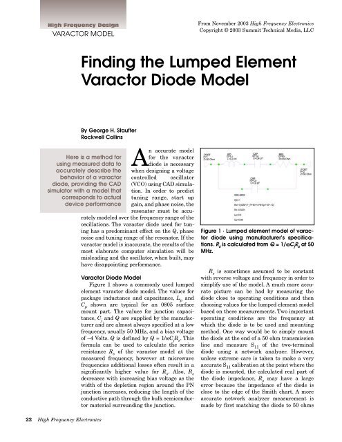
Figure 1 shows a commonly used lumped<br />
element varactor diode model. The values for<br />
package inductance and capacitance, L p<br />
and<br />
C p<br />
shown are typical for an 0805 surface<br />
mount part. The values for junction capacitance,<br />
C j<br />
and Q are supplied by <strong>the</strong> manufacturer<br />
and are almost always specified at a low<br />
frequency, usually 50 MHz, and a bias voltage<br />
of –4 Volts. Q is defined by Q = 1/ωC j<br />
R s<br />
. This<br />
formula can be used to calculate <strong>the</strong> series<br />
resistance R s<br />
of <strong>the</strong> varactor model at <strong>the</strong><br />
measured frequency, however at microwave<br />
frequencies additional losses often result in a<br />
significantly higher value for R s<br />
. Also, R s<br />
decreases with increasing bias voltage as <strong>the</strong><br />
width of <strong>the</strong> depletion region around <strong>the</strong> PN<br />
junction increases, reducing <strong>the</strong> length of <strong>the</strong><br />
conductive path through <strong>the</strong> bulk semiconductor<br />
material surrounding <strong>the</strong> junction.<br />
Figure 1 · <strong>Lumped</strong> element model of varactor<br />
diode using manufacturer’s specifications.<br />
R s<br />
is calculated from Q = 1/ωC j<br />
R s<br />
at 50<br />
MHz.<br />
R s<br />
is sometimes assumed to be constant<br />
with reverse voltage and frequency in order to<br />
simplify use of <strong>the</strong> model. A much more accurate<br />
picture can be had by measuring <strong>the</strong><br />
diode close to operating conditions and <strong>the</strong>n<br />
choosing values for <strong>the</strong> lumped element model<br />
based on <strong>the</strong>se measurements. Two important<br />
operating conditions are <strong>the</strong> frequency at<br />
which <strong>the</strong> diode is to be used and mounting<br />
method. One way would be to simply mount<br />
<strong>the</strong> diode at <strong>the</strong> end of a 50 ohm transmission<br />
line and measure S 11<br />
of <strong>the</strong> two-terminal<br />
diode using a network analyzer. However,<br />
unless extreme care is taken to make a very<br />
accurate S 11<br />
calibration at <strong>the</strong> point where <strong>the</strong><br />
diode is mounted, <strong>the</strong> calculated real part of<br />
<strong>the</strong> diode impedance, R s<br />
may have a large<br />
error because <strong>the</strong> impedance of <strong>the</strong> diode is<br />
close to <strong>the</strong> edge of <strong>the</strong> Smith chart. A more<br />
accurate network analyzer measurement is<br />
made by first matching <strong>the</strong> diode to 50 ohms<br />
22 High Frequency Electronics
High Frequency Design<br />
VARACTOR MODEL<br />
(a)<br />
Figure 3 · Microstrip test fixture with tapped line and<br />
bias circuit.<br />
(b)<br />
Figure 2 · <strong>Varactor</strong> diode model matched to 50 ohms<br />
using microstrip tapped line (a); S 11<br />
from 2 to 4 GHz (b).<br />
Figure 4 · Tapped line and bias network models from EM<br />
simulation connected to diode model.<br />
at <strong>the</strong> frequency of interest. A matching<br />
structure which uses only<br />
microstrip elements is preferable<br />
because it can be analyzed quite<br />
accurately using an EM simulator<br />
and its effect in <strong>the</strong> circuit can <strong>the</strong>n<br />
be accounted for when calculating <strong>the</strong><br />
model parameters.<br />
An Accurate <strong>Model</strong> is Required<br />
for VCO Design<br />
A recent 3 GHz VCO design<br />
required that <strong>the</strong> resonator circuit be<br />
optimized for best phase noise and<br />
tuning range, yet also allow for adequate<br />
production margin. A suitable<br />
varactor diode was selected based on<br />
<strong>the</strong> required range of capacitance<br />
variation. In order to begin to accurately<br />
characterize <strong>the</strong> diode, <strong>the</strong><br />
model with values supplied by <strong>the</strong><br />
manufacturer was matched at 3 GHz<br />
using a microstrip network as shown<br />
in Figure 2a. The swept frequency<br />
response from 2 to 4 GHz describes a<br />
loop on <strong>the</strong> Smith chart as shown in<br />
Figure 2b. At 3 GHz <strong>the</strong> resonance<br />
loop passes through <strong>the</strong> center of <strong>the</strong><br />
Smith chart indicating critical coupling.<br />
From this point it is a simple matter<br />
to add microstrip elements to produce<br />
a practical circuit to be used as<br />
a test fixture. The layout is shown in<br />
Figure 3 and includes a biasing network<br />
consisting of a radial stub and a<br />
high impedance quarter wave line. At<br />
3 GHz <strong>the</strong> bias network is an RF<br />
short at <strong>the</strong> cathode terminal.<br />
The S-parameters of <strong>the</strong> bias network<br />
and <strong>the</strong> tapped line are calculated<br />
individually using an EM simulation<br />
program and <strong>the</strong> results are<br />
used in <strong>the</strong> measurement fixture<br />
schematic in Figure 4.<br />
This layout was reproduced on 20<br />
mil Rogers 4003 board, and this 2 x 2<br />
inch board was mounted on a test fixture<br />
block, shown in Figure 5. The<br />
network analyzer was calibrated at<br />
<strong>the</strong> coax connector, with <strong>the</strong> reference<br />
plane brought to <strong>the</strong> edge of <strong>the</strong><br />
board using a 16.7 ps port extension.<br />
The S 11<br />
measurements were <strong>the</strong>n<br />
made at bias voltages over a 0-20 V<br />
range while sweeping from 2 to 4<br />
GHz.<br />
The S 11<br />
measurements were<br />
saved and imported into <strong>the</strong> CAD<br />
program. After <strong>the</strong>se measurements,<br />
all that remains to be done is to<br />
adjust C j<br />
and R s<br />
of <strong>the</strong> model of<br />
Figure 4 so that <strong>the</strong> measured S 11<br />
agrees with S 11<br />
calculated from<br />
Figure 4 over <strong>the</strong> entire 2 to 4 GHz<br />
frequency range for each value of bias<br />
24 High Frequency Electronics
High Frequency Design<br />
VARACTOR MODEL<br />
Figure 5 · Test fixture with diode mounted for S 11<br />
measurement.<br />
Figure 6 · Measured and modeled response at V = –4 V.<br />
voltage. The CAD program employs a<br />
built in optimizer to accomplish this<br />
task. The results of one such optimization<br />
for a bias voltage of –4 V are<br />
shown in Figure 6 where <strong>the</strong> measured<br />
and modeled values are seen to<br />
match closely.<br />
A graph of <strong>the</strong> results after optimizing<br />
<strong>the</strong> model to <strong>the</strong> measured<br />
data at all bias voltages is shown in<br />
Figure 7. Here C j<br />
and R s<br />
are plotted<br />
versus bias voltage. Also shown is <strong>the</strong><br />
capacitance variation computed using<br />
<strong>the</strong> equation for <strong>the</strong> junction capacitance<br />
of an abrupt junction diode :<br />
( )<br />
C<br />
j<br />
0<br />
Cj<br />
( V) =<br />
⎛ V ⎞<br />
+<br />
⎝<br />
⎜1<br />
⎠<br />
⎟<br />
. 75<br />
05 .<br />
(1)<br />
Q of <strong>the</strong> varactor at 3 GHz calculated<br />
from measured values of R s<br />
and<br />
C j<br />
using Q = 1/ωC j<br />
R s<br />
is shown plotted<br />
versus bias voltage in Figure 8.<br />
Figure 9 shows <strong>the</strong> model derived<br />
from <strong>the</strong> measured data. C j<br />
is determined<br />
from equation (1) and R s<br />
calculated<br />
from equation (2), a polynomial<br />
with coefficients chosen to fit <strong>the</strong> R s<br />
vs. bias voltage curve in Figure 7:<br />
−5 4 −3 3<br />
Rs = 4. 025 × 10 v − 1.<br />
84 × 10 v<br />
2<br />
+ . 029v<br />
− . 205v+<br />
2.<br />
056<br />
(2)<br />
Resonator Design with <strong>the</strong><br />
Accurate <strong>Diode</strong> <strong>Model</strong><br />
The actual resonator used in <strong>the</strong><br />
3 GHz VCO is a shorted microstrip<br />
line shunted at <strong>the</strong> input by <strong>the</strong> var-<br />
Figure 7 · C j<br />
and R s<br />
computed from model and <strong>the</strong> calculated<br />
value of C(v).<br />
Figure 8 · <strong>Varactor</strong> Q versus bias voltage at 3 GHz.<br />
26 High Frequency Electronics
High Frequency Design<br />
VARACTOR MODEL<br />
(a)<br />
Figure 9 · Derived model at 3 GHz with equations for C j<br />
and R s<br />
as functions of V.<br />
actor diode and coupled to <strong>the</strong> active device of <strong>the</strong> VCO<br />
by a small value series capacitor, as diagrammed in<br />
Figure 10a. As shown in Figure 10b, <strong>the</strong> calculated resonator<br />
loss using <strong>the</strong> derived model from Figure 9 is low<br />
enough at resonance for oscillations to start when connected<br />
to one port of an unstable active device having a<br />
reflection gain of 6 dB or more over <strong>the</strong> frequency range<br />
from 2.8 to 3.2 GHz.<br />
Conclusion<br />
At a bias voltage of –4 VDC, R s<br />
first calculated from Q<br />
= 1/ωC j<br />
R s<br />
using <strong>the</strong> manufacturer’s value of Q at 50 MHz<br />
was 0.67 ohms. Compare this optimistic value to <strong>the</strong> more<br />
realistic value of R s<br />
= 1.64 ohms derived from <strong>the</strong> measurements<br />
described at 3 GHz. The first value would have<br />
resulted in an overly optimistic design and <strong>the</strong> engineer<br />
would have been left wondering where it had all gone<br />
wrong. A model that accurately behaves like <strong>the</strong> actual<br />
device gives much more confidence in <strong>the</strong> simulated<br />
results and may avoid disappointment when <strong>the</strong> hardware<br />
is built and tested.<br />
References<br />
1. D. Johnson, “Tuning <strong>Diode</strong> Design Techniques,”<br />
Motorola Application Note AN551.<br />
2. “<strong>Varactor</strong> SPICE <strong>Model</strong>s for RF VCO Applications,”<br />
Application Note APN1004, Alpha Industries.<br />
Author Information<br />
George Stauffer is a Principal Engineer at Rockwell<br />
Collins Government Systems, Germantown, MD. His primary<br />
interest is microwave syn<strong>the</strong>sizer design. He can be<br />
reached by e-mail at: ghstauff@rockwellcollins.com<br />
(b)<br />
Figure 10 · Layout of 2.8-3.2 GHz resonator with requirements<br />
for start-up and steady state oscillations (a), and<br />
<strong>the</strong> resonance loops at 0 and 20 VDC tuning voltages<br />
calculated from <strong>the</strong> improved diode model (b).<br />
CALL FOR TUTORIAL ARTICLES<br />
High Frequency Electronics includes a tutorial<br />
article in each issue. These are targeted to both<br />
new engineers and those who have been working<br />
in o<strong>the</strong>r areas of specialization. We are<br />
accepting proposals for articles on following<br />
topics for publication in <strong>the</strong>se 2004 issues:<br />
March:<br />
April:<br />
May:<br />
September:<br />
October:<br />
Personal Area Networks (PANs)<br />
Power Amplifier Linearization<br />
Filter Specifications<br />
Balanced Circuits<br />
Optical Detectors and Preamps<br />
Send an abstract or outline by e-mail to: editor@<br />
highfrequencyelectronics.com. If you have<br />
questions, send <strong>the</strong>m by e-mail or telephone to<br />
Gary Breed, Editorial Director, at 608-845-3965.<br />
28 High Frequency Electronics