Inside the Microwave Connector - High Frequency Electronics
Inside the Microwave Connector - High Frequency Electronics
Inside the Microwave Connector - High Frequency Electronics

You also want an ePaper? Increase the reach of your titles
YUMPU automatically turns print PDFs into web optimized ePapers that Google loves.
<strong>High</strong> <strong>Frequency</strong> Design<br />
CONNECTORS<br />
From December 2010 <strong>High</strong> <strong>Frequency</strong> <strong>Electronics</strong><br />
Copyright © 2010 Summit Technical Media, LLC<br />
<strong>Inside</strong> <strong>the</strong> <strong>Microwave</strong><br />
<strong>Connector</strong>: Materials<br />
and Construction<br />
By Gary Breed<br />
Editorial Director<br />
At first glance, <strong>the</strong><br />
This month’s tutorial is an<br />
construction of<br />
overview of RF/microwave<br />
RF/microwave<br />
connector specifications for<br />
materials and dimensional<br />
manufacturing tolerances,<br />
intended to familiarize<br />
engineers with important<br />
non-electrical parameters<br />
connectors seems quite<br />
straightforward. Physical<br />
dimensions are dictated<br />
largely by <strong>the</strong> desired<br />
combination of RF characteristics—characteristic<br />
impedance, power<br />
handling (current capacity and voltage breakdown),<br />
and compatibility with typical cables.<br />
The choice of body metal, plating, and dielectric<br />
material will depend on environmental<br />
requirements—water, corrosion, temperature,<br />
air pressure (altitude), mating-unmating<br />
cycles, shock and vibration. Of course, construction<br />
must be compatible with interface<br />
standards for <strong>the</strong> mating methods: threaded,<br />
bayonet, friction fit, etc.<br />
For non-critical, general-purpose use, <strong>the</strong><br />
specifications might stop at this point, but<br />
<strong>the</strong>re are many additional requirements and<br />
refinements to basic specs that must be considered<br />
for specific applications.<br />
Example: MIL-STD-348B Type N <strong>Connector</strong><br />
The most comprehensive set of mechanical<br />
specifications for RF/microwave connectors is<br />
MIL-STD-348B [1]. I’ve chosen <strong>the</strong> common<br />
“series N” connector to illustrate <strong>the</strong> requirements<br />
called out in this important document.<br />
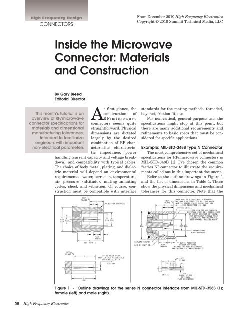
Refer to <strong>the</strong> outline drawings in Figure 1<br />
and <strong>the</strong> list of dimensions in Table 1. These<br />
show <strong>the</strong> physical dimensions and mechanical<br />
tolerances for this connector. Note that <strong>the</strong><br />
Figure 1 · Outline drawings for <strong>the</strong> series N connector interface from MIL-STD-358B [1];<br />
female (left) and male (right).<br />
50 <strong>High</strong> <strong>Frequency</strong> <strong>Electronics</strong>
<strong>High</strong> <strong>Frequency</strong> Design<br />
CONNECTORS<br />
interface between <strong>the</strong> connectors is<br />
defined, not <strong>the</strong> body of <strong>the</strong> connector<br />
behind <strong>the</strong> mating section, which can<br />
vary considerably to accommodate<br />
various types of cables and mounting<br />
methods. The connectors may also be<br />
configured with straight or angled<br />
bodies, and as adapters between<br />
series N and o<strong>the</strong>r connector types.<br />
<strong>Connector</strong> Materials<br />
MIL standards for RF/microwave<br />
connectors (MIL-PRF-39012, MIL-<br />
DTL-3655D, and o<strong>the</strong>rs) include <strong>the</strong><br />
following requirements for materials:<br />
· <strong>Connector</strong> bodies are mainly brass,<br />
with some types specified as beryllium<br />
copper.<br />
· Brass bodied connectors must be<br />
silver plated over a copper underplate.<br />
· Beryllium copper bodied connectors<br />
must be gold plated to a minimum<br />
of 50 microinches (1.27 µm) over a<br />
copper flash plating.<br />
· Standard connectors must be made<br />
with materials classified as nonmagnetic.<br />
· Nickel plating is not to to be used<br />
on connector bodies, due to passive<br />
intermodulation (PIM) potential.<br />
· Dissimilar metals are not allowed<br />
to be in contact with each o<strong>the</strong>r.<br />
· Center contact springs must be<br />
made from beryllium copper.<br />
· Critical contacts—male pins and<br />
socket contacts—must be gold plated<br />
to a minimum of 50 microinches<br />
(1.27 µm) over a nickel underplating<br />
of 50 microinches (1.27 µm).<br />
· Non-critical portions of <strong>the</strong> mating<br />
surfaces must be plated as needed<br />
to meet performance specs, but may<br />
not be silver plated.<br />
· Insulation in standard connectors<br />
is specified as FEP fluorocarbon or<br />
polytetrafluoroethylene (PTFE).<br />
PTFE parts may be molded from<br />
resins, and ei<strong>the</strong>r type may be used<br />
for extruded/molded parts.<br />
· For connectors with a sealed interface,<br />
<strong>the</strong> gasket material is typically<br />
silicone rubber.<br />
Table 1 · Guide to dimensions and manufacturing tolerances of series N<br />
connector interfaces of Figure 1; female (left) and male (right).<br />
Notes: The above list includes standard<br />
connectors only. Special applications<br />
may require o<strong>the</strong>r materials,<br />
such as stainless steel for connector<br />
bodies (not electrical mating surfaces),<br />
neoprene gasketing, higherperformance<br />
dielectric materials, and<br />
different plating materials and/or<br />
thicknesses.<br />
<strong>Connector</strong> Testing<br />
The most extensive part of all<br />
MIL specifications is testing to verify<br />
compliance with <strong>the</strong> performance<br />
specifications. Although this tutorial<br />
concerns <strong>the</strong> construction of connectors,<br />
readers are advised to review<br />
<strong>the</strong> specified test methods. They provide<br />
valuable insight into <strong>the</strong> reasons<br />
for <strong>the</strong> various specifications, and<br />
provide a basis for testing of non-military<br />
connectors as well.<br />
Commercial <strong>Connector</strong>s<br />
Many high performance commercial<br />
microwave applications use connectors<br />
with <strong>the</strong> same specifications<br />
as MIL types. However, connectors<br />
for general-purpose applications use<br />
a wide range of materials to achieve<br />
lower cost and more more efficient<br />
high-volume manufacturing.<br />
Among o<strong>the</strong>r materials found in<br />
lower-cost connectors are metal<br />
alloys suitable for casting, including<br />
zinc-based metals. Machined connectors<br />
mainly use brass, but plating<br />
selections vary widely.<br />
Dielectric materials in low-cost<br />
commercial connectors may include<br />
polyethylene and polystyrene, possibly<br />
glass-filled for high voltage<br />
breakdown performance.<br />
For almost all non-military applications<br />
designated as “microwave”<br />
(as opposed to “RF” or “general purpose”)<br />
a connector based on MIL<br />
specifications is <strong>the</strong> best choice.<br />
These connectors will provide consistent<br />
electrical performance and<br />
mechanical reliability. Using a common<br />
specification also assures uniform<br />
performance among products<br />
from different vendors.<br />
Summary<br />
This tutorial is a brief overview of<br />
<strong>the</strong> dimensional and materials specifications<br />
for microwave connectors.<br />
RF/microwave engineers will be<br />
familiar with electrical specifications<br />
such as VSWR, power handling and<br />
voltage breakdown. This article also<br />
provides a look at additional requirements<br />
for manufacturing tolerances<br />
and selection of materials for connector<br />
bodies and mating contacts.<br />
Reference<br />
1. MIL-STD-348B, Dept. of<br />
Defense Interface Standard, Feb.<br />
2009 draft.<br />
52 <strong>High</strong> <strong>Frequency</strong> <strong>Electronics</strong>