Multiband Monopole Antenna for Wireless Communication
Multiband Monopole Antenna for Wireless Communication
Multiband Monopole Antenna for Wireless Communication

Create successful ePaper yourself
Turn your PDF publications into a flip-book with our unique Google optimized e-Paper software.
High Frequency Design<br />
MULTIBAND ANTENNA<br />
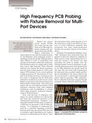
Figure 2 · Return loss versus σ at f = 1.5 GHz and f =<br />
5 GHz.<br />
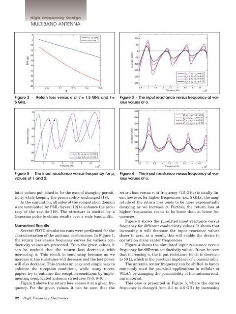
Figure 3 · The input reactance versus frequency at various<br />
values of σ.<br />
Figure 5 · The input reactance versus frequency <strong>for</strong> µ r<br />
values of 1 and 2.<br />
Figure 4 · The input resistance versus frequency at various<br />
values of σ.<br />
lated values published in <strong>for</strong> the case of changing permittivity<br />
while keeping the permeability unchanged [18].<br />
In the simulation, all sides of the computation domain<br />
were terminated by PML layers [19] to enhance the accuracy<br />
of the results [19]. The structure is excited by a<br />
Gaussian pulse to obtain results over a wide bandwidth.<br />
Numerical Results<br />
Several FDTD simulation runs were per<strong>for</strong>med <strong>for</strong> the<br />
characterization of the antenna per<strong>for</strong>mance. In Figure 1,<br />
the return loss versus frequency curves <strong>for</strong> various conductivity<br />
values are presented. From the given values, it<br />
can be noticed that the return loss decreases with<br />
increasing σ. This result is convincing because as we<br />
increase σ, the resistance will decrease and the lost power<br />
will also decrease. This creates an easy and simple way to<br />
enhance the reception conditions, while many recent<br />
papers try to enhance the reception conditions by implementing<br />
complicated antenna structures [3-6, 9-10].<br />
Figure 2 shows the return loss versus σ at a given frequency.<br />
For the given values, it can be seen that the<br />
return loss versus σ at frequency (1.5 GHz) is totally linear,<br />
however, <strong>for</strong> higher frequencies (i.e., 5 GHz), the magnitude<br />
of the return loss tends to be more exponantially<br />
decaying as we increase σ. Further, the return loss at<br />
higher frequencies seems to be lower than at lower frequencies.<br />
Figure 3 shows the simulated input reactance versus<br />
frequency <strong>for</strong> different conductivity values. It shows that<br />
increasing σ will decrease the input reactance values<br />
closer to zero, as a result, this will enable the device to<br />
operate on many center frequencies.<br />
Figure 4 shows the simulated input resistance versus<br />
frequency <strong>for</strong> different conductivity values. It can be seen<br />
that increasing σ, the input resistance tends to decrease<br />
to 50 Ω, which is the practical impdance of a coaxial cable.<br />
The antenna center frequency can be shifted to bands<br />
commonly used <strong>for</strong> practical applications in cellular or<br />
WLAN by changing the permeability of the antenna coating<br />
material.<br />
This case is presented in Figure 5, where the center<br />
frequency is changed from 2.3 to 2.6 GHz by increasing<br />
22 High Frequency Electronics