Operating Instructions - PowerBox Systems
Operating Instructions - PowerBox Systems
Operating Instructions - PowerBox Systems

You also want an ePaper? Increase the reach of your titles
YUMPU automatically turns print PDFs into web optimized ePapers that Google loves.
<strong>PowerBox</strong> Sensor<br />
2. Specification<br />
<strong>Operating</strong> voltage:<br />
4.0 Volts to 9.0 Volts<br />
Power supply:<br />
2 x 5-cell NiCd or NiMH batteries,<br />
or 2 x 2-cell Lithium-Polymer batteries<br />
Max. load:<br />
5.0 Amps<br />
Voltage loss:<br />
approx. 0.35 Volts (diode / regulator losses)<br />
Voltage stabilisation:<br />
2 x 5.9 Volts (+/- 0.1 Volt)<br />
Idle current: approx. 5µA<br />
Temperature range:<br />
-10°C to +75°C<br />
Weight:<br />
35 g (complete incl. all cables)<br />
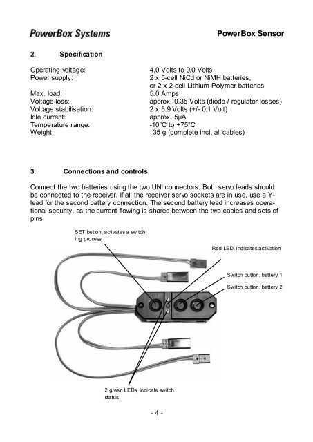
3. Connections and controls<br />
Connect the two batteries using the two UNI connectors. Both servo leads should<br />
be connected to the receiver. If all the receiver servo sockets are in use, use a Y-<br />
lead for the second battery connection. The second battery lead increases operational<br />
security, as the current flowing is shared between the two cables and sets of<br />
pins.<br />
SET button, activates a switching<br />
process<br />
Red LED, indicates activation<br />
Switch button, battery 1<br />
Switch button, battery 2<br />
2 green LEDs, indicate switch<br />
status<br />
- 4 -