Pilatus PC-21 - HT-Modellbau
Pilatus PC-21 - HT-Modellbau
Pilatus PC-21 - HT-Modellbau

Create successful ePaper yourself
Turn your PDF publications into a flip-book with our unique Google optimized e-Paper software.
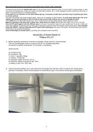
Building instruction <strong>PC</strong>-<strong>21</strong> Version 0.5e/ 30.10.2008<br />
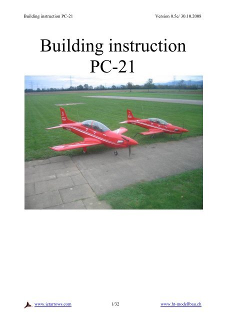
Building instruction<br />
<strong>PC</strong>-<strong>21</strong><br />
www.jetarrows.com<br />
1/32 www.ht-modellbau.ch
Building instruction <strong>PC</strong>-<strong>21</strong> Version 0.5e/ 30.10.2008<br />
Table of contents<br />
1 Technical Data .........................................................................................................................2<br />
2 Kit contents: .............................................................................................................................4<br />
3 Recommended accessories.......................................................................................................5<br />
4 Fuselage....................................................................................................................................6<br />
4.1 Frame................................................................................................................................6<br />
4.2 Wing tube.........................................................................................................................8<br />
4.3 Turbine assembly .............................................................................................................9<br />
4.4 Turbine cover .................................................................................................................10<br />
5 Wing.......................................................................................................................................11<br />
5.1 Ailerons..........................................................................................................................11<br />
5.1.1 Ailerons hinges.......................................................................................................11<br />
5.2 Landing flaps..................................................................................................................13<br />
5.3 Landing flaps covering...................................................................................................14<br />
6 Elevators.................................................................................................................................17<br />
6.1 Elevator hinges...............................................................................................................17<br />
6.2 Elevator servo.................................................................................................................17<br />
6.3 Elevator assembly ..........................................................................................................18<br />
7 Rudder....................................................................................................................................19<br />
7.1 Rudder hinge ..................................................................................................................19<br />
7.2 Rudder linking................................................................................................................19<br />
7.3 Rudder flaps ...................................................................................................................20<br />
8 Cockpit and cab frame ...........................................................................................................<strong>21</strong><br />
8.1 Cockpit rear wall............................................................................................................24<br />
8.2 Cockpit attachment.........................................................................................................25<br />
8.3 Canopy and framework................................................................................................. 26<br />
9 Landing gear...........................................................................................................................27<br />
9.1 Nose landing gear cover.................................................................................................27<br />
9.2 Main landing gear cover.................................................................................................29<br />
10 Control throws and Centre of gravity.................................................................................31<br />
10.1 <strong>PC</strong>-<strong>21</strong> 1:3.7 (big)...........................................................................................................32<br />
1 Technical Data<br />
Scale 1 : 4.8 1:3.7<br />
Length 2.38m 2.98 m<br />
Wingspan 1.85m 2.38 m<br />
Weight From 12kg From 19kg<br />
Engine<br />
Turboprop<br />
JetCat SPT 5<br />
Controlled functions Ailerons<br />
Elevator<br />
Rudder<br />
Break flap<br />
Engine<br />
Front wheel<br />
Undercarriage<br />
Wheel breaks<br />
www.jetarrows.com<br />
2/32 www.ht-modellbau.ch
Building instruction <strong>PC</strong>-<strong>21</strong> Version 0.5e/ 30.10.2008<br />
2<br />
www.jetarrows.com<br />
3/32 www.ht-modellbau.ch
Building instruction <strong>PC</strong>-<strong>21</strong> Version 0.5e/ 30.10.2008<br />
Kit contents:<br />
1 x fuselage GRP/CRP<br />
1 x turbine cover GRP/CRP<br />
1 x milled plywood stretching set<br />
2 x wings<br />
2 x winglets GRP<br />
1 x wing tubes<br />
2 x Elevator (GRP or Styro Balsa)<br />
1 x ruder GRP<br />
1 x canopy framework GRP<br />
1 x canopy clear<br />
1 x Cockpit from ABS with plywood parts<br />
1 x GRP Spinner<br />
1 x mounting set<br />
3<br />
www.jetarrows.com<br />
4/32 www.ht-modellbau.ch
Building instruction <strong>PC</strong>-<strong>21</strong> Version 0.5e/ 30.10.2008<br />
Recommended accessories<br />
Function<br />
Accessories<br />
Ailerons, Elevator, Rudder 5 x Futaba F-9206<br />
Nose landing gear servo Futaba F-9202<br />
Landing gear<br />
<strong>HT</strong>-<strong>Modellbau</strong> (Jet-1A)<br />
Engine Turboprop JetCat SPT 5<br />
4<br />
www.jetarrows.com<br />
5/32 www.ht-modellbau.ch
Building instruction <strong>PC</strong>-<strong>21</strong> Version 0.5e/ 30.10.2008<br />
Fuselage<br />
All GRP parts has residues from Parting agent and need to be cleaned<br />
If necessary rework the cut off seam.<br />
4.1 Frame<br />
Glue the front undercarriage support like<br />
the image show.<br />
picture 1 shows the den nose gear pit<br />
Cut the front undercarriage cover after the outliner.<br />
Resins the frame with epoxy mixture (epoxy thickened with micro balloon and cotton flakes) in<br />
the fuselage like the picture shows. But rough on first the fuselage with sand paper.<br />
picture 2 shows the glued front<br />
undercarriage cover<br />
www.jetarrows.com<br />
6/32 www.ht-modellbau.ch
Building instruction <strong>PC</strong>-<strong>21</strong> Version 0.5e/ 30.10.2008<br />
Insert the front and back turbine frames in the fuselage and check if the positions fit with your<br />
turboprop engine.<br />
Then resins the frame with epoxy mixture (epoxy thickened with micro balloon and cotton flakes)<br />
in the fuselage like the picture shows. But rough on first the fuselage with sand paper.<br />
picture 3 shows the mounted front turbine<br />
frame<br />
picture 4 shows the mounted back turbine<br />
frame<br />
4.2<br />
www.jetarrows.com<br />
7/32 www.ht-modellbau.ch
Building instruction <strong>PC</strong>-<strong>21</strong> Version 0.5e/ 30.10.2008<br />
Wing tube<br />
Coat the wing tube with separating means. Insert the guide tube at the right position in the<br />
fuselage and mount the wing tube. Afterwards resins the guide tube with fabric glass-chamfers.<br />
picture 5 shows the wing tube<br />
4.3<br />
www.jetarrows.com<br />
8/32 www.ht-modellbau.ch
Building instruction <strong>PC</strong>-<strong>21</strong> Version 0.5e/ 30.10.2008<br />
Turbine assembly<br />
First cut out the holes for the two tail pipes (specify position with the turbine). Lay out the cover<br />
with thermal protection mat.<br />
picture 6 shows the inserted turbine<br />
picture 7 shows the turbine cover from the side<br />
picture 8 Shows the tail pipe<br />
Downwards<br />
Note: the tail pipe must be inserted left<br />
downward, quite upward. (See picture)<br />
Upwards<br />
4.4<br />
www.jetarrows.com<br />
9/32 www.ht-modellbau.ch
Building instruction <strong>PC</strong>-<strong>21</strong> Version 0.5e/ 30.10.2008<br />
Turbine cover<br />
picture 9 shows the turbine<br />
cover<br />
First, bore on both sides of the cover the holes for the two turn closures according to the picture.<br />
Then resin a support with the help of stick. After hardening of the turn closures can be mounted.<br />
Afterward mount the linkage (a1) for the fixation of the pins B treat it with parting agent and then<br />
resins in together with the bowden cable. This gives the attachment of the cover.<br />
picture 10 shows the turbine cover<br />
cover<br />
B<br />
A<br />
(a2)<br />
55<br />
C<br />
(a1)<br />
20<br />
225<br />
110<br />
Bowden cable<br />
Bowden cable<br />
fuselage<br />
Bore afterwards the ∅ 3 mm holes for the pin C in the fuselage. Parting agents the fuselage and<br />
bore the two holes in the fuselage for the pins B somewhat more largely than the pins, so that the<br />
cover fits. The same with the two holes for the pins C, but bore this time the holes in the cover<br />
more largely! Grinding the pins (C to sticking in the cover and B in the fuselage). Install the<br />
cover with pins and Bowden cable and examine if it fit.<br />
If everything fits, stick both pins C in the cover and B in the fuselage with Epoxy resin mixture.<br />
At the same time also the piece Bowden cable pipe for the attachment will be glued.<br />
For this assemble the linkage (a2) and align it. After hardening curing the linkage (a2) at the end<br />
with a black felt-tip pen mark, mount the cover and close the shutter so that the black colour is<br />
painted to the fuselage. Now bore the two holes for it.<br />
5<br />
www.jetarrows.com<br />
10/32 www.ht-modellbau.ch
Building instruction <strong>PC</strong>-<strong>21</strong> Version 0.5e/ 30.10.2008<br />
Wing<br />
5.1 Ailerons<br />
5.1.1 Ailerons hinges<br />
small middle big<br />
2x Ailerons outside 2x Ailerons middle 2 x Ailerons inside<br />
8 x Elevator<br />
3 x Rudder<br />
Put the fuselage upside on a table, mouth the wings and fix them. Insert the landing flaps and<br />
positioning ½ mm distance between flap and wings. Hold the ailerons and mark the position for<br />
the hinges. Afterward you can cut the slots. To glue put slightly below resin mixture, and mouth<br />
the aileron with mounted hinges (Approximately 1.2-1.5mm distance between ailerons and wing),<br />
and fix it at each transition with screw fixation, so that the rudder are equal. Then the landing<br />
flaps hinges can be glued with resin mixture. After curing remove the wings and glue the hinge<br />
definitely in the wings.<br />
At the elevator and rudder exactly the same approach.<br />
picture 11 Fix the aileron during gluing<br />
www.jetarrows.com<br />
11/32 www.ht-modellbau.ch
Building instruction <strong>PC</strong>-<strong>21</strong> Version 0.5e/ 30.10.2008<br />
picture 12 Cross section of the rudder hinge<br />
5.2<br />
www.jetarrows.com 12/32 www.ht-modellbau.ch
Building instruction <strong>PC</strong>-<strong>21</strong> Version 0.5e/ 30.10.2008<br />
Landing flaps<br />
For the landing flap hinges on the cuts in<br />
the wing are already made. On the two<br />
flaps they must be cited as shown in the<br />
picture.<br />
picture 13 shows the landing flap hinge<br />
with the servo<br />
M2x10 countersunk<br />
When you have wood wings, the servo<br />
fixation is done in the same way as for the<br />
elevator.<br />
For the CSF wings they are already<br />
finished.<br />
Please note that the linkage is mounted as<br />
shown in the picture.<br />
picture 14 shows the landing flap hinge<br />
with the servo<br />
The hinges assemble (with screw store varnish secure).<br />
picture 15 shows the landing flap hinge<br />
www.jetarrows.com<br />
13/32 www.ht-modellbau.ch
Building instruction <strong>PC</strong>-<strong>21</strong> Version 0.5e/ 30.10.2008<br />
5.3 Landing flaps covering<br />
The landing flap hinges can be switched after<br />
covering or squirting with the settled ABS parts<br />
as in the illustration.<br />
picture 16 shows the cover of the landing flap<br />
hinges<br />
picture 17 shows the cover of the landing flap<br />
hinges<br />
www.jetarrows.com<br />
14/32 www.ht-modellbau.ch
Building instruction <strong>PC</strong>-<strong>21</strong> Version 0.5e/ 30.10.2008<br />
Near the linkage<br />
1mm plywood<br />
Near the linkage M2.5 x 10<br />
countersunk screw<br />
Fixatio n and<br />
Cuttin g near the linkage<br />
Near the linkage<br />
2mm + 6mm plywood<br />
picture 18 shows the landing flap covering<br />
www.jetarrows.com 15/32 www.ht-modellbau.ch
Building instruction <strong>PC</strong>-<strong>21</strong> Version 0.5e/ 30.10.2008<br />
Place for the linkage<br />
13 mm<br />
6 mm 8 mm<br />
1 mm<br />
3 mm<br />
picture 19 shows the landing flap covering from the top on the linkage<br />
13 mm<br />
3.5 mm<br />
3.5 mm<br />
5.5 mm<br />
5.5 mm<br />
picture 20 shows the landing flap covering from the top<br />
6<br />
www.jetarrows.com<br />
16/32 www.ht-modellbau.ch
Building instruction <strong>PC</strong>-<strong>21</strong> Version 0.5e/ 30.10.2008<br />
Elevators<br />
6.1 Elevator hinges<br />
The countersinks fort he rudder hinges are already done. Glue the elevator hinges like the one on<br />
the ailerons.<br />
6.2 Elevator servo<br />
The servo fixations is already resins in the elevator (prepared for Futaba servos)<br />
picture <strong>21</strong> Shows the Servo fixation<br />
After the installation of the Servos using rubber<br />
sleeves (a servo component) cut out the GRP<br />
servo cover after the outline. Leave the cover<br />
part for the linkage as in the picture somewhat<br />
longer. Bore afterwards the holes for the<br />
attachment and the cover with screws 2,5x12<br />
install.<br />
picture 22 shows the servo cover<br />
6.3<br />
www.jetarrows.com<br />
17/32 www.ht-modellbau.ch
Building instruction <strong>PC</strong>-<strong>21</strong> Version 0.5e/ 30.10.2008<br />
Elevator assembly<br />
The elevator is installed with aluminium putting pipe and with both CRP pegs. First the two pegs<br />
on a page sharpen. Install afterwards the elevator for control. If everything fits bonds the two<br />
pegs with resin mixture into the elevators.<br />
Attention: Peg first with parting agent treats!<br />
picture 23 shows the elevator<br />
If everything is dried, the drilling for fixing bolt can take place. Indicate in addition the position<br />
of aluminium to putting pipe at the elevator and the drilling for the screw make. Afterwards<br />
elevators again install and into the putting pipe through the drilling make. Bore afterwards a M4<br />
threads.<br />
picture 24 shows the elevator attachment<br />
45mm<br />
7<br />
www.jetarrows.com<br />
18/32 www.ht-modellbau.ch
Building instruction <strong>PC</strong>-<strong>21</strong> Version 0.5e/ 30.10.2008<br />
Rudder<br />
7.1 Rudder hinge<br />
The 3 slots for the hinges in the rudder are already done.<br />
Glue the hinges like on the ailerons<br />
7.2 Rudder linking<br />
Insert the servo into the rudder and the position of the rudder horn and linkages mark. After<br />
milling out, resins the rudder horn with resin mixture. Mill out a slotted hole in accordance with<br />
the design for the linkage. To the linkage the servo with the yoke begins screws in. Screw now<br />
the linkage through the hole on the yoke. Screw in best completely, since no lock nut can be<br />
installed with screw Loctite to secure.<br />
picture 25 shows the position of the rudder servo<br />
25<br />
picture 26 shows the position of the rudder servo<br />
www.jetarrows.com<br />
19/32 www.ht-modellbau.ch
Building instruction <strong>PC</strong>-<strong>21</strong> Version 0.5e/ 30.10.2008<br />
Putting pipe in front with wood peg from above push in and by the fuselage bore From downside<br />
with a plastic plug fasten. The pipe either sticks together in the vertical stabilizer or with the<br />
servo pit bolt.<br />
165 mm<br />
parallel<br />
12 mm<br />
Putting pipe<br />
Wood peg<br />
picture 27 shows the rudder attachment<br />
Plastic plug<br />
7.3 Rudder flaps<br />
Cut the slots for the rudder flaps as shown in the picture and glue them in.<br />
8<br />
www.jetarrows.com<br />
20/32 www.ht-modellbau.ch
Building instruction <strong>PC</strong>-<strong>21</strong> Version 0.5e/ 30.10.2008<br />
Cockpit and cab frame<br />
Cut put both cockpit tubes, stick together and strengthen with plywood parts.<br />
picture 28 shows the cockpit<br />
picture 29 shows the cockpit floor<br />
Stick seats and instrument panel in accordance with the illustrations.<br />
picture 30 shows the seat<br />
picture 31 shows instrument panel<br />
www.jetarrows.com<br />
<strong>21</strong>/32 www.ht-modellbau.ch
Building instruction <strong>PC</strong>-<strong>21</strong> Version 0.5e/ 30.10.2008<br />
Spray the cockpit with spray box dark grey or black. Bond the Seat.<br />
picture 32 shows the sprayed cockpit<br />
www.jetarrows.com<br />
22/32 www.ht-modellbau.ch
Building instruction <strong>PC</strong>-<strong>21</strong> Version 0.5e/ 30.10.2008<br />
8.1<br />
www.jetarrows.com<br />
23/32 www.ht-modellbau.ch
Building instruction <strong>PC</strong>-<strong>21</strong> Version 0.5e/ 30.10.2008<br />
Cockpit rear wall<br />
Glue the cockpit rear wall from the 3 ABS together<br />
picture 33 shows the cockpit rear wall<br />
Glue the plywood mounting stuck in the fuselage and fixes the rear wall with double tape or a<br />
screw.<br />
picture 34 shows the fixation of the cockpit rear wall<br />
8.2<br />
www.jetarrows.com<br />
24/32 www.ht-modellbau.ch
Building instruction <strong>PC</strong>-<strong>21</strong> Version 0.5e/ 30.10.2008<br />
Cockpit attachment<br />
For the attachment of the cockpit in the rear part of the cut-out a plywood board is bonded at a<br />
value of 185mm. Fasten the cockpit with klett catch to the board and in front.<br />
185 mm<br />
picture 35 shows the Cockpit attachment<br />
150 mm<br />
Brett<br />
8.3<br />
www.jetarrows.com<br />
25/32 www.ht-modellbau.ch
Building instruction <strong>PC</strong>-<strong>21</strong> Version 0.5e/ 30.10.2008<br />
Canopy and framework<br />
Canopy frameworks of the outline out with the<br />
friction disk cut out.<br />
Transparent hood cut out and with the cab frames<br />
stick together.<br />
Cab frame attachment<br />
picture 36 shows the cab attachment<br />
9<br />
www.jetarrows.com<br />
26/32 www.ht-modellbau.ch
Building instruction <strong>PC</strong>-<strong>21</strong> Version 0.5e/ 30.10.2008<br />
Landing gear<br />
9.1 Nose landing gear cover<br />
Cut the cover in the middle longitudinal. Then make the cut-outs for the hinges in the fuselage.<br />
picture 37 Shows the closed nose landing gear cover<br />
Cut-outs in the fuselage for<br />
the hinges<br />
2/3<br />
1/3<br />
~5mm<br />
~5mm<br />
M3x10<br />
countersunk<br />
After bonding the hinge (on the fuselage, they can be screwed) glue 6 screws with Flexzap like<br />
shown in the picture (previously rubbing).<br />
Then install three silicone tubes between the two covers according to the photos.<br />
picture 38 Shows the nose landing gear cover<br />
www.jetarrows.com<br />
27/32 www.ht-modellbau.ch
Building instruction <strong>PC</strong>-<strong>21</strong> Version 0.5e/ 30.10.2008<br />
picture 39 Shows the silicon tubes on the nose landing gear cove<br />
9.2<br />
www.jetarrows.com 28/32 www.ht-modellbau.ch
Building instruction <strong>PC</strong>-<strong>21</strong> Version 0.5e/ 30.10.2008<br />
Main landing gear cover<br />
The holes in the main landing gear cover are already drilled.<br />
M2x5 countersunk screw<br />
Stopp nut M2<br />
27 mm<br />
picture 40 shows the main landing gear cover<br />
www.jetarrows.com<br />
29/32 www.ht-modellbau.ch
Building instruction <strong>PC</strong>-<strong>21</strong> Version 0.5e/ 30.10.2008<br />
168 mm<br />
picture 41 shows the cover fixation on the main landing gear<br />
www.jetarrows.com<br />
30/32 www.ht-modellbau.ch
Building instruction <strong>PC</strong>-<strong>21</strong> Version 0.5e/ 30.10.2008<br />
10 Control throws and Centre of gravity<br />
www.jetarrows.com<br />
31/32 www.ht-modellbau.ch
Building instruction <strong>PC</strong>-<strong>21</strong> Version 0.5e/ 30.10.2008<br />
10.1 <strong>PC</strong>-<strong>21</strong> 1:3.7 (big)<br />
Aileron<br />
+20, -15 mm (based on the wing outside)<br />
Elevators<br />
± 25 mm<br />
Rudder<br />
± 40 mm<br />
Landing flaps Pos 1 15 mm (measured with the fuselage)<br />
Pos 2 65 mm<br />
Expo aprox. 30 – 40 % depending upon taste.<br />
The batteries should be place in front as far as<br />
possible (receiver, valves on servo board of<br />
the nose gear), the emphasis is measured 200-<br />
<strong>21</strong>0 mm from the wing front edge. With the<br />
installation of the servo cables on the fact it<br />
respects that they are distant from the battery<br />
and automatic controller as far as possible.<br />
The antenna should be shifted outside of the<br />
fuselage.<br />
200 – <strong>21</strong>0 mm<br />
www.jetarrows.com<br />
32/32 www.ht-modellbau.ch