Operating Instructions - PowerBox Systems
Operating Instructions - PowerBox Systems
Operating Instructions - PowerBox Systems

Create successful ePaper yourself
Turn your PDF publications into a flip-book with our unique Google optimized e-Paper software.
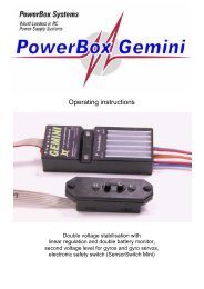
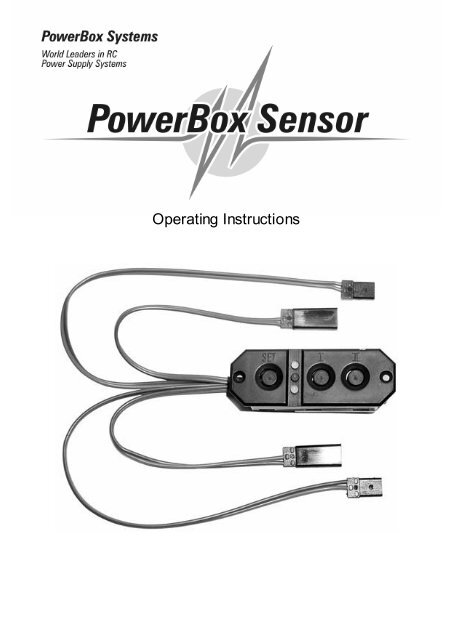
<strong>Operating</strong> <strong>Instructions</strong>
<strong>PowerBox</strong> Sensor<br />
Dear customer, we are delighted that you have decided to purchase the POWER<br />
BOX Sensor switch backer from our range. This is a modern, high-performance<br />
switch system with integral battery backer for your valuable model aircraft, containing<br />
two entirely independent electronic switches in addition to the dual battery coupling<br />
facility. We have also managed to combine these features with a linear stabilised<br />
power supply voltage for receiver and servos. The linear stabilised voltage is<br />
generated by two independent IC-controlled voltage regulators of extremely lowloss<br />
design.<br />
The switch backer is very simple and safe in operation (the same SensorSwitch<br />
system is used in our <strong>PowerBox</strong> “Competition” and “Champion”), but it is important<br />
that you understand its features if you are to make best use of it. Please read<br />
through these instructions so that you understand your new accessory fully.<br />
We wish you much pleasure and success with your POWER BOX Sensor.<br />
Inhaltsverzeichnis<br />
1. Product description................................................................. Page 2<br />
2. Specification........................................................................... Page 4<br />
3. Connections and controls ....................................................... Page 4<br />
4. <strong>Operating</strong> and Safety Notes..................................................... Page 5<br />
5. Using the Sensor-Switch......................................................... Page 6<br />
6. Guarantee conditions.............................................................. Page 7<br />
1. Product description<br />
The POWER BOX Sensor is the world’s first switch system for small to mediumsized<br />
models which combines the functions of a battery backer, dual de-coupled<br />
batteries, plus two independent electronic switches and two IC-controlled linear<br />
voltage regulators, each independent of the other. Naturally, each battery can be<br />
switched on and off separately. Our system also includes a SET button which provides<br />
an absolutely secure power-on / power-off method and protection against the<br />
effects of vibration.<br />
The <strong>PowerBox</strong> Sensor provides a linearly stabilised voltage of exactly 5.9 Volts<br />
for powering your receiver and servos. This fulfils exactly the requirements of all RC<br />
manufacturers who state a maximum permissible voltage of 6.0 Volts for their RC<br />
components.<br />
- 2 -
<strong>PowerBox</strong> Sensor<br />
This ground-breaking overall design enables you to use the latest lightweight Lithium-Polymer<br />
cells as well as standard 5-cell NC and Hydride batteries, without<br />
exceeding the maximum voltage of 6.0 Volts.<br />
As you would expect, we can also supply these modern Lithium-Polymer batteries<br />
for your power supplies. We are the only manufacturer to rely exclusively upon<br />
the Li-Po cells made by IONITY AG in Germany; we do not use any cell types<br />
made in Asia.<br />
The POWERBOX Sensor is equipped with LED power-on indicators for both power<br />
circuits. If you switch one battery on, the associated green LED glows. When both<br />
batteries are active, both LEDs light up.<br />
The total voltage loss in the <strong>PowerBox</strong> Sensor (de-coupling diodes and voltage<br />
regulators) is about 0.35 V, which is so low that the volume of waste heat is almost<br />
negligible. The specified maximum continuous current is 5.0 Amps, which means<br />
that it easily cope with 6 - 8 standard servos or 5 - 7 digital servos.<br />
However, the rated continuous current of 5.0 A does not reflect the capacity of the<br />
electronics; it is a function of the size of heat-sink employed. The electronic circuit is<br />
able to handle twice the specified power without problem.<br />
The heat-sink is mounted on the rear of the unit, and it is important to ensure that<br />
the waste heat generated can be dissipated efficiently through this component. If<br />
you notice that the heat-sink becomes hot in use (above 60° Celsius), this is a reliable<br />
indication that the servos you are using are consuming a disproportionate<br />
amount of energy (power). Check your servos, linkages, pushrods etc. !<br />
The unit features double battery and receiver cables, each with 0.34 mm² conductors.<br />
This means that voltage drop in the cables is very slight even at maximum<br />
load.<br />
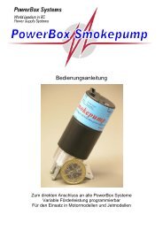
The schematic circuit diagram below<br />
is intended to clarify the inter-related<br />
functions of the POWER BOX Sensor.<br />
It shows in graphic form how the<br />
individual components are linked together.<br />
- 3 -
<strong>PowerBox</strong> Sensor<br />
2. Specification<br />
<strong>Operating</strong> voltage:<br />
4.0 Volts to 9.0 Volts<br />
Power supply:<br />
2 x 5-cell NiCd or NiMH batteries,<br />
or 2 x 2-cell Lithium-Polymer batteries<br />
Max. load:<br />
5.0 Amps<br />
Voltage loss:<br />
approx. 0.35 Volts (diode / regulator losses)<br />
Voltage stabilisation:<br />
2 x 5.9 Volts (+/- 0.1 Volt)<br />
Idle current: approx. 5µA<br />
Temperature range:<br />
-10°C to +75°C<br />
Weight:<br />
35 g (complete incl. all cables)<br />
3. Connections and controls<br />
Connect the two batteries using the two UNI connectors. Both servo leads should<br />
be connected to the receiver. If all the receiver servo sockets are in use, use a Y-<br />
lead for the second battery connection. The second battery lead increases operational<br />
security, as the current flowing is shared between the two cables and sets of<br />
pins.<br />
SET button, activates a switching<br />
process<br />
Red LED, indicates activation<br />
Switch button, battery 1<br />
Switch button, battery 2<br />
2 green LEDs, indicate switch<br />
status<br />
- 4 -
<strong>PowerBox</strong> Sensor<br />
4. <strong>Operating</strong> and Safety Notes<br />
Be sure to use top-quality batteries of low internal resistance to power your receiving<br />
system. Do not use receiver batteries of low capacity, as one pack may be required<br />
to provide full power to the system for the whole of a flight if the other battery<br />
should fail.<br />
Always use battery cells of the same type.<br />
We recommend that you use batteries with a capacity of at least 1700 mAh; for<br />
larger models we suggest packs of up to 3000 mAh capacity. You can use either<br />
Nickel-Cadmium batteries (NiCd), Nickel-Metal-Hydride batteries (NiMH) or<br />
Lithium-Polymer batteries.<br />
We strongly recommend our own range of high-quality batteries which are designed<br />
to be suitable for a wide range of applications in modelling.<br />
We particularly recommend our Lithium-Polymer battery packs with integral<br />
safety and charge electronics. These are based exclusively on the latest cells<br />
made by IONITY AG of Germany.<br />
In principle the POWER BOX Sensor can also be used with two separate receivers.<br />
However, please be sure to read the instructions provided by the radio manufacturer,<br />
as not all receivers work properly in tandem. In all cases the basic rule is<br />
to keep the two receivers away from each other - they should be spaced about 25 -<br />
30 cm apart inside the model.<br />
The POWER BOX Sensor fulfils the requirements of the standard EMV directives,<br />
as reflected by the CE symbol on the unit.<br />
The CE symbol guarantees that the unit fulfils the statutory regulations relating to<br />
interference-free operation. This involves checking the unit’s radiation of interference<br />
and susceptibility to outside interference. The switch backer does not suffer<br />
interference from other electrical devices except under extremely severe conditions,<br />
and it does not radiate interference which could affect other devices (receiver, servos).<br />
The backer is designed exclusively for use in modelling applications and is only<br />
approved for use in radio-controlled models.<br />
The unit is designed for use with Direct Current power sources typified by 5-cell NC<br />
or NiMH batteries or two-cell Lithium-Polymer batteries.<br />
The unit must never be connected to a mains-powered PSU!<br />
- 5 -
<strong>PowerBox</strong> Sensor<br />
5. Using the Sensor-Switch<br />
The sensor buttons do not switch the current for the receiver and servos. The actual<br />
switching process is carried out by the two electronic switches in the POWER<br />
BOX Sensor, which are independent of each other.<br />
The controls on the front panel consist of three push-buttons, two green LEDs and<br />
one red LED.<br />
You will find two countersunk holes into which the mounting screws (supplied) fit.<br />
These are used to attach the switch to the model.<br />
The push-buttons are marked “SET” and “I” and “II”.<br />
The purpose of the slightly recessed “SET” button is to prepare and execute a<br />
switching process. Holding the “SET” button pressed in for about one second<br />
“arms” both internal switches, and the red LED lights up. You can now switch either<br />
or both power circuits on by pressing the other push-buttons “I” and “II”. This<br />
method of switching allows you to check each power circuit or battery separately.<br />
To switch off the POWER BOX Sensor, first hold the “SET” button pressed in,<br />
then press the push-buttons “I” and “II” in turn to switch both batteries off again.<br />
This new switching system as our own in-house development, and offers you the<br />
highest possible standard of security.<br />
When the electronic switches are in the “stand-by” state, i.e. the batteries are<br />
switched off, they draw an idle current of about 5 micro-Amps. This corresponds to<br />
a small fraction of the self-discharge rate of normal batteries.<br />
However, if you do not intend to use your model for a long period we recommend<br />
that you disconnect them from the POWER BOX Sensor, especially if you are using<br />
a Lithium-Polymer battery.<br />
The POWER BOX Sensor is virtually impervious to vibration, but it is still good<br />
practice to mount the unit in an area of the model where vibration levels are low.<br />
Please note that the GRP fuselage sides of a power model are not suitable, as they<br />
are always subject to considerable vibration. You can remedy the situation by cutting<br />
a ply plate (2 - 3 mm thick) about 3 cm larger than the switch aperture, and<br />
gluing it in the appropriate position. The plate damps the vibration, and at the same<br />
time provides plenty of “meat” into which the retaining screws of the POWER BOX<br />
Sensor can “bite”.<br />
- 6 -
<strong>PowerBox</strong> Sensor<br />
6. Guarantee conditions:<br />
During the production process each <strong>PowerBox</strong> Sensor undergoes a series of<br />
tests. We take the maintenance of the highest quality standards very seriously.<br />
We grant a 24 month guarantee on our products, valid from the initial date of purchase.<br />
The guarantee covers proven material faults, which will be corrected by us<br />
at no charge to you. We wish to emphasise expressly that we reserve the right to<br />
replace the unit if a repair is impossible for economic reasons.<br />
Repairs which our Service Department carries out for you do not extend the guarantee<br />
period.<br />
Misuse and maltreatment, such as reversed polarity, excessive voltage, the effects<br />
of damp and fuel invalidate the guarantee. The same applies to faults which<br />
are due to severe wear or excessive vibration.<br />
Additional claims, e.g. for consequent damages, are excluded. We do not accept<br />
liability for the device or the use of the device.<br />
If you have to return the unit to us, note that we cannot accept liability for transit<br />
damage or the loss of your shipment. If you need to make a claim under guarantee,<br />
send the unit to us at the following address, and be sure to include proof of purchase:<br />
Modellbau-Deutsch<br />
Hindenburgstraße 33<br />
86609 Donauwörth<br />
Germany<br />
Liability exclusion:<br />
We are not in a position to ensure that this battery backer is operated correctly, nor<br />
that the entire radio control system has been maintained properly.<br />
For this reason we are unable to accept liability for loss, damages or costs which<br />
result from the use of the <strong>PowerBox</strong> Sensor, or are connected with its use in any<br />
way. Unless otherwise prescribed by binding law, our obligation to pay compensation,<br />
regardless of the legal argument employed, is limited to the invoice value of<br />
those of our products which were immediately and directly involved in the event<br />
which caused the damage.<br />
Donauwörth, April 2004<br />
Yours - the Modellbau-Deutsch Team<br />
<strong>PowerBox</strong> <strong>Systems</strong>, Germany<br />
- 7 -
<strong>PowerBox</strong> Sensor<br />
<strong>PowerBox</strong> <strong>Systems</strong><br />
Modellbau-Deutsch<br />
Hindenburgstraße 33<br />
86609 Donauwörth<br />
Tel: +49-0906-22559<br />
Fax: +49-0906-22459<br />
info@<strong>PowerBox</strong>-<strong>Systems</strong>.com<br />
www.<strong>PowerBox</strong>-<strong>Systems</strong>.com<br />
- 8 -