HM Series Hydronic Boiler.pdf - Hurlcon Heating
HM Series Hydronic Boiler.pdf - Hurlcon Heating
HM Series Hydronic Boiler.pdf - Hurlcon Heating

You also want an ePaper? Increase the reach of your titles
YUMPU automatically turns print PDFs into web optimized ePapers that Google loves.
INSTALLATION AND OPERATING INSTRUCTIONS I INSTALLATION AND OPERATING INSTRUCTIONS<br />
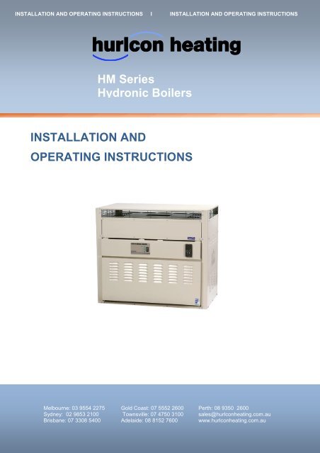
<strong>HM</strong> <strong>Series</strong><br />
<strong>Hydronic</strong> <strong>Boiler</strong>s<br />
INSTALLATION AND<br />
OPERATING INSTRUCTIONS<br />
Melbourne: 03 9554 2275 Gold Coast: 07 5552 2600 Perth: 08 9350 2600<br />
Sydney: 02 9853 2100 Townsville: 07 4750 3100 sales@hurlconheating.com.au<br />
Brisbane: 07 3308 5400 Adelaide: 08 8152 7600 www.hurlconheating.com.au<br />
4/10/2010
INDEX<br />
1.0 INTRODUCTION .................................................................................................................... 3<br />
1.1 NOTICE TO INSTALLERS ........................................................................................ 3<br />
2.0 <strong>HM</strong> MODELS AVAILABLE .................................................................................................. 4<br />
2.1 STANDARD EQUIPMENT – <strong>HM</strong> MODELS ........................................................... 4<br />
3.0 INSTALLATION .................................................................................................................... 5<br />
3.1 SAFETY RULES ......................................................................................................... 5<br />
3.2 BOILER DIMENSIONS .............................................................................................. 6<br />
3.3 INDOOR INSTALLATION ......................................................................................... 6<br />
3.4 VENTILATION – Air supply to the boiler ................................................................. 7<br />
3.5 CLEARANCES ............................................................................................................ 8<br />
3.6 ELECTRICAL CONNECTION .................................................................................. 8<br />
3.7 GAS CONNECTION ................................................................................................... 9<br />
3.8 PUMP SELECTION: ................................................................................................... 9<br />
4.0 COMMISSIONING............................................................................................................... 10<br />
4.1 STARTING BOILER ................................................................................................ 10<br />
4.2 TESTING BURNER PRESSURE .......................................................................... 10<br />
4.3 CHECKING MINIMUM GAS PRESSURE ........................................................... 11<br />
4.4 ADJUSTING MINIMUM GAS PRESSURE .......................................................... 11<br />
4.5 FLOW SWITCH ........................................................................................................ 12<br />
5.0 OPERATING INSTRUCTIONS ......................................................................................... 12<br />
5.1 FROST PROTECTION ........................................................................................... 12<br />
5.2 ENERGY SAVING TIPS ......................................................................................... 12<br />
5.3 CONTROL SYSTEMS ............................................................................................ 13<br />
………………………………………………………………………………………………. 14<br />
5.4 MAINTENANCE ....................................................................................................... 14<br />
6.0 GAS CONVERSION ........................................................................................................... 15<br />
6.1 BURNER CONVERSION ....................................................................................... 15<br />
6.2 GAS PIPE SIZING TABLES .................................................................................. 16<br />
7.0 TROUBLESHOOTING ....................................................................................................... 16<br />
………………………………………………………………………………………………. 17<br />
8.0 <strong>HM</strong> SERIES WIRING DIAGRAM ...................................................................................... 18<br />
8.1 MODEL 200 – 400 ................................................................................................... 18<br />
8.2 MODEL 500 .............................................................................................................. 18<br />
9.0 ONE YEAR LIMITED WARRANTY………………………………………………………………………….19<br />
Inst195 <strong>HM</strong> <strong>Series</strong> <strong>Hydronic</strong> <strong>Boiler</strong> V10_10 2
1.0 INTRODUCTION<br />
Congratulations on your purchase of a <strong>Hurlcon</strong> <strong>Hydronic</strong> <strong>Boiler</strong>. Correct installation and service of your new<br />
heating system and correct chemical maintenance of the water will ensure years of service. The <strong>HM</strong> <strong>Series</strong> <strong>Boiler</strong><br />
is a compact lightweight and efficient gas fired hydronic boiler. It is equipped with features that take advantage of<br />
new technology developed exclusively by <strong>Hurlcon</strong>.<br />
The <strong>Hurlcon</strong> is a floor mounted atmospheric boiler with a built in balanced flue for outdoor installation. The power<br />
output is controlled by an integrated electronic controller to maintain the set point water temperature over a wide<br />
load range. In addition, the <strong>Hurlcon</strong> <strong>Hydronic</strong> <strong>Boiler</strong> is equipped with electronic ignition. The electronic display<br />
tells at a glance the operational status of the boiler.<br />
Note:<br />
The appliance is not intended for use by young children or infirm person without supervision. Please ensure that<br />
young children are supervised to ensure that they do not play with the appliance.<br />
1.1 NOTICE TO INSTALLERS<br />
This is a Floor Mounted - External - <strong>Hydronic</strong> Central <strong>Heating</strong> <strong>Boiler</strong><br />
For use with Natural Gas or LP Gas as per the attached data label.<br />
Australian Gas Association Tested AGA Approval No. 6423<br />
The information below is given to assist the installer with the installation of this range of HYDRONIC <strong>HM</strong> 200 - 500<br />
<strong>Boiler</strong>s. Please read it carefully in order to make the installation as easy as possible and to ensure the system<br />
works well and conforms to the necessary government regulations.<br />
PLEASE READ THESE INSTRUCTIONS BEFORE STARTING THE INSTALLATION.<br />
It is important that this boiler is installed and serviced as detailed in these instructions<br />
by an AUTHORISED person.<br />
This boiler is to be installed and serviced to the requirements of the<br />
Local Building, Gas, Water and Electricity Authorities.<br />
These instructions are to be held by the owner / user after installation.<br />
This boiler must not be used for a SPA or POOL <strong>Boiler</strong><br />
This appliance must be installed in accordance with the installation instructions, local gas fitting regulations, the<br />
AGA Installation Code AG 601 and any other relevant statutory authorities.<br />
Refer to data plate for details of gas type, gas consumption and burner pressure.<br />
Inst195 <strong>HM</strong> <strong>Series</strong> <strong>Hydronic</strong> <strong>Boiler</strong> V10_10 3
2.0 <strong>HM</strong> MODELS AVAILABLE<br />
Model 250 300 400<br />
Input MJ (NG) 240 288 350<br />
Output kW 55 66 80<br />
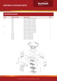
2.1 STANDARD EQUIPMENT – <strong>HM</strong> MODELS<br />
Electronic control including.<br />
<br />
<br />
<br />
<br />
PID control with auto tune.<br />
Set point shift via building automation system<br />
Displays set and flow temperature.<br />
Electronic ignition<br />
Safety devices<br />
<br />
<br />
<br />
<br />
Built in flow switch<br />
Built in run on timer for pump<br />
Manual reset high limit<br />
Reliable in high wind areas<br />
Built to last<br />
<br />
<br />
<br />
<br />
All copper double row heat exchanger<br />
Bronze headers with brass sensor pockets<br />
Fully powder coated steel cabinet<br />
Powder coated flue terminal<br />
Efficiency<br />
Hot surface intermittent pilot<br />
Highly efficient stainless steel burners<br />
Double row - counter flow heat exchanger<br />
Out door compensation ready, just add outdoor sensor<br />
Electronic gas modulation turn down 3 : 1<br />
Ease of installation<br />
<br />
<br />
<br />
<br />
<br />
Fully plumbed ready to go<br />
All electrical pre wired including three pin power supply.<br />
Flow switch, run-on timer installed and wired<br />
Weather proof balanced flue external installation<br />
Terminal box for pump, outdoor compensation and room thermostat.<br />
Inst195 <strong>HM</strong> <strong>Series</strong> <strong>Hydronic</strong> <strong>Boiler</strong> V10_10 4
3.0 INSTALLATION<br />
THIS APPLIANCE MUST BE INSTALLED BY AN AUTHORISED PERSON.<br />
Refer to boiler data plate for specifications of gas type, gas consumption, burner pressure and water pressure.<br />
This appliance must be installed in accordance with local regulations and A.G.A. Installation Code AG 601.<br />
The boiler should always be installed downstream of the pump. The water connections are located on the left<br />
hand side of the boiler. Right hand connection models are available by special order. The inlet and outlet are<br />
clearly marked. Water connections are 1 ½” BSP FI.<br />
The <strong>Hurlcon</strong> <strong>Boiler</strong> is fitted with a built in flow switch and will not start unless full of water and the pump is<br />
operating.<br />
The <strong>Hurlcon</strong> <strong>Boiler</strong> incorporates a balanced flue terminal and is suitable for outdoor installation. An internal model<br />
is available on request.<br />
WARNING: An approved pressure relief valve must be fitted to this boiler before operation.<br />
3.1 SAFETY RULES<br />
For your safety – read before lighting<br />
This appliance is equipped with an ignition device, which automatically lights the pilot. Do not try to light the pilot<br />
by hand.<br />
BEFORE OPERATING smell all around the appliance area for gas. Be sure to smell next to the floor because<br />
some gas is heavier than air and will settle on the floor.<br />
Safety<br />
What to do if you smell gas<br />
<br />
<br />
<br />
<br />
Do not try to light any gas appliance.<br />
Do not touch any electrical switch.<br />
Turn off the gas supply at the gas meter.<br />
Immediately call your gas supplier or licensed gas fitter.<br />
NOTE. Some gases are heavier than air and it may be necessary to smell for leaks at floor level.<br />
House keeping<br />
<br />
<br />
<br />
Do not store or use flammable liquid or chemicals near this appliance.<br />
Do not use aerosols in the vicinity of this gas appliance.<br />
Keep this appliance free of debris.<br />
WARNING: Should overheating occur or the gas supply fail to shut off, turn off the manual gas control valve to<br />
the appliance.<br />
Do not use this boiler if any part has been under water.<br />
Inst195 <strong>HM</strong> <strong>Series</strong> <strong>Hydronic</strong> <strong>Boiler</strong> V10_10 5
3.2 BOILER DIMENSIONS<br />
3.3 INDOOR INSTALLATION<br />
If the <strong>HM</strong> <strong>Boiler</strong> is to be installed indoors, an indoor draught hood kit must be purchased from <strong>Hurlcon</strong> and installed<br />
on the <strong>HM</strong> <strong>Boiler</strong> to convert it to an indoor model.<br />
Product code numbers for draught hoods are:<br />
<strong>Boiler</strong> model Indoor top model Flue size Part number<br />
<strong>HM</strong> 200 DH 20 175 mm 10966<br />
<strong>HM</strong> 250 DH 25 175 mm 10964<br />
<strong>HM</strong> 300 DH 30 200 mm 10967<br />
<strong>HM</strong> 400 DH 40 250 mm 10965<br />
<strong>HM</strong> 500 DH 50 300 mm 10968<br />
A flue no smaller than the draught diverter diameter must be installed and terminated with an approved gas flue<br />
cowl (not a Chinaman’s hat) 600mm above any roofline that is within 1.5 metres horizontally from the flue.<br />
Inst195 <strong>HM</strong> <strong>Series</strong> <strong>Hydronic</strong> <strong>Boiler</strong> V10_10 6
600<br />
3.4 VENTILATION – AIR SUPPLY TO THE BOILER<br />
When installing the boiler indoors, it is imperative that an adequate supply of fresh air is provided for combustion.<br />
Failure to provide adequate ventilation voids all warranties and may be a danger to persons or property. Please<br />
refer to AGA 601 for full details.<br />
Two permanent openings shall be provided directly to outside. The openings shall be located to ensure the<br />
distance between the top of the upper opening and the ceiling of the room or enclosure, and the distance between<br />
the bottom of the lower opening and the floor of the room or enclosure does not exceed 5% of the height of the<br />
room or enclosure.<br />
The minimum vertical dimension of any free ventilation opening shall be 6 mm.<br />
The minimum free ventilation area provided by each opening shall be:<br />
MODELS <strong>HM</strong> 200 250 300 400 500<br />
AREA mm 2 65,000 80,000 100,000 130,000 160,000<br />
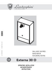
The following diagram is provided as a guide only. All flueing and installation work must be carried out by an<br />
authorized person. Flueing must conform to local regulations and to A.G.A. installation code AG 601. Care must<br />
be taken to provide the correct ventilation and correct flueing materials in close proximity to combustible surfaces.<br />
Approved gas<br />
termination cowl<br />
Bolted<br />
sleeve to<br />
connect flue<br />
1500<br />
Draft diverter<br />
purchased<br />
from <strong>Hurlcon</strong><br />
Upper grille for fresh<br />
air ventilation<br />
Lower grille for fresh<br />
air ventilation<br />
A <strong>Hurlcon</strong> indoor draught diverter must be fitted to unit in accordance with <strong>Hurlcon</strong>’s Instructions and<br />
Installation Codes before the boiler can be enclosed.<br />
Do not install spa blowers in the same room as a gas boiler. This is potentially dangerous to spa users.<br />
Do not store chemicals or fuel in the same room as the gas boiler. This may cause fire or explosion.<br />
When installing in a garage the <strong>HM</strong> <strong>Boiler</strong> must be installed 450 mm above floor level.<br />
Inst195 <strong>HM</strong> <strong>Series</strong> <strong>Hydronic</strong> <strong>Boiler</strong> V10_10 7
3.5 CLEARANCES<br />
The boiler must be installed at least 500 mm from any combustible surface. Clearances must comply with AG 601.<br />
Clearances from non combustible surfaces are:<br />
Front<br />
Both sides<br />
Rear<br />
Above<br />
Combustible Surfaces<br />
500mm<br />
500mm<br />
500mm<br />
1500mm<br />
500mm Minimum<br />
Recommended service clearances 500mm on both sides and 1000 in front for component removal, connections<br />
and servicing.<br />
<strong>Boiler</strong> must be installed on a fireproof base.<br />
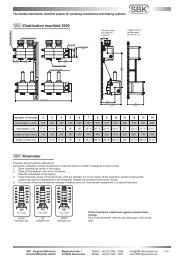
3.6 ELECTRICAL CONNECTION<br />
The boiler is supplied with a standard 10 amp 3 pin plug for connection to a 240V 10 amp GPO. The boiler<br />
incorporates a 240/24 VAC transformer which supplies power to the control circuit only and must not be used for<br />
any additional equipment. All equipment connected to mains power should be protected by an RCD circuit<br />
breaker. The boiler has a 240 volt power supply for the pump electrical connection which incorporates the pump<br />
run on timer. A terminal strip is provided for a 24 volt room thermostat and the addition of an outdoor<br />
compensation sensor.<br />
If the supply cord is damaged, it must be replaced by the manufacturer or its service agent or a similarly qualified<br />
person in order to avoid a hazard.<br />
Electrical connections<br />
T1<br />
T2<br />
ROOM<br />
T’STAT<br />
O’DOOR<br />
SENSOR<br />
PUMP<br />
5 amp<br />
max<br />
Connect circulator to<br />
these connections.<br />
240 Volts- 5 Amps max.<br />
Use relays for higher<br />
capacity or 3 phase<br />
pumps.<br />
Field wiring of outdoor sensor by others<br />
Remove loop to connect room thermostat – 24 VOLT<br />
The thermostat cannot be powered from this circuit. A dry<br />
contact must be provided.<br />
Inst195 <strong>HM</strong> <strong>Series</strong> <strong>Hydronic</strong> <strong>Boiler</strong> V10_10 8
3.7 GAS CONNECTION<br />
The gas connection is on the left side of the boiler. A 20 mm (25mm for <strong>HM</strong> 500) flare nipple is provided for gas<br />
line connection. An approved manual shut off valve must be installed in the gas fitting line before the boiler so that<br />
the gas can be turned off and the boiler removed for servicing if required. The gas valves should be sized the<br />
same as the gas fitting line to prevent excessive pressure drop in the gas pipe.<br />
The gas fitting line should be installed by an authorised person and comply with local regulations and A.G.A. code<br />
AG 601. The gas line from the meter will usually be of a larger size than the gas inlet connection. Therefore a<br />
reduction to the boiler connection fitting will be necessary. The reduction should be as close to the boiler as<br />
possible.<br />
Before using the boiler, test all connections for gas leaks using soapy water.<br />
The boiler gas valve has a built in pressure regulator. A ⅛” pressure test point is provided on the burner manifold.<br />
On starting the boiler, a manometer must be used and burner pressure checked against the boiler data plate. The<br />
gas valve regulator may need adjustment to correct manifold pressure. Incorrect burner pressure may void<br />
warranty.<br />
3.8 PUMP SELECTION:<br />
If a pump has not been supplied by your Dealer as part of this <strong>Boiler</strong> package, it will be necessary to size the<br />
Pump in accordance with the following flow rate and pressure drop chart. System pressure drop will need to be<br />
added to the corresponding boiler pressure drop.<br />
FLOW RATES & PRESSURE DROPS<br />
<strong>Boiler</strong> Model 250 300 400<br />
10 Deg C Rise<br />
Flow l/s 1.33 1.59 2.13<br />
<strong>Boiler</strong> pressure drop kPa 1.90 2.50 5.10<br />
15 Deg C Rise<br />
Flow l/s 0.89 1.06 1.42<br />
<strong>Boiler</strong> pressure drop kPa 1.60 2.00 4.20<br />
20 Deg C Rise<br />
Flow l/s 0.66 0.80 1.06<br />
<strong>Boiler</strong> pressure drop kPa 0.44 0.69 1.47<br />
Inst195 <strong>HM</strong> <strong>Series</strong> <strong>Hydronic</strong> <strong>Boiler</strong> V10_10 9
4.0 COMMISSIONING<br />
4.1 STARTING THE BOILER<br />
1. Purge gas line of any air and wait five minutes for gas to clear.<br />
2. Plug three pin plug into a suitable power point and switch on. The READY indicator should light. Digital<br />
controller should now operate and indicate water temperature<br />
3. Pump should start, the FLOW indicator should light.<br />
4. Turn Burner Switch ON.<br />
5. After a few seconds, the burner should ignite. Ignition will be confirmed by the BURNER indicator.<br />
6. If the burner fails to light, check FLOW indicator is on. Turn burner switch off then on to reset ignition system.<br />
4.2 TESTING BURNER PRESSURE<br />
1. Set up manometer<br />
2. Turn boiler “OFF”.<br />
3. Remove screw from ⅛” brass test point located on outlet side of gas valve/burner manifold<br />
4. Connect manometer tube to test point<br />
5. Turn boiler “ON” and wait for main burner to ignite and gas modulation to go to fully open.<br />
6. Once main burner has ignited, the manometer must indicate the nominal burner pressure listed below.<br />
7. To adjust gas valve regulator, remove regulator adjustment cap and, using a screwdriver, turn plastic bush<br />
clockwise to increase, anti-clockwise to decrease burner pressure.<br />
Maximum inlet gas pressure is:<br />
Natural Gas 3.5 kPa Propane Gas 3.5 kPa ULPG 3.5 kPa<br />
Nominal burner pressure is:<br />
<strong>HM</strong> 250 <strong>HM</strong> 300 <strong>HM</strong> 400<br />
Natural Gas kPa High Flame 0.82 0.82 0.75<br />
Low Flame 0.10 0.10 0.10<br />
Propane Gas kPa High Flame 2.50 2.50 2.50<br />
Low Flame 0.80 0.80 0.80<br />
ULPG kPa High Flame 2.00 2.00 2.00<br />
Low Flame 0.80 0.80 0.80<br />
Inst195 <strong>HM</strong> <strong>Series</strong> <strong>Hydronic</strong> <strong>Boiler</strong> V10_10 10
4.3 CHECKING MINIMUM GAS PRESSURE<br />
1. Set up manometer<br />
2. Turn boiler “OFF”.<br />
3. Remove screw from ⅛” brass test point located on outlet side of gas valve/burner manifold<br />
4. Connect manometer tube to test point<br />
5. Turn boiler “ON” and wait for main burner to ignite.<br />
6. Press and hold EXIT button for 5 seconds. Hand indicator lights.<br />
7. Press and hold Decrease button to move gas ball valve to lowest setting.<br />
8. Read gas pressure.<br />
4.4 ADJUSTING MINIMUM GAS PRESSURE<br />
Increasing minimum gas pressure<br />
1. Press Increase button until correct pressure is reached.<br />
2. Release locking screw.<br />
3. Move actuator to lowest setting.<br />
4. Tighten locking screw.<br />
5. Return to automatic operation by pressing EXIT for 5 seconds.<br />
Decreasing minimum gas pressure<br />
1. Release locking screw.<br />
2. Move actuator toward the maximum setting.<br />
3. Tighten locking screw.<br />
4. Press and hold Decrease button to move gas valve to lowest setting.<br />
5. Repeat until correct minimum gas pressure is achieved.<br />
6. Return to automatic operation by pressing EXIT for 5 seconds.<br />
Inst195 <strong>HM</strong> <strong>Series</strong> <strong>Hydronic</strong> <strong>Boiler</strong> V10_10 11
4.5 FLOW SWITCH<br />
The <strong>Hurlcon</strong> <strong>Boiler</strong> has an inbuilt flow switch which allows the burner to operate only when the system is full of<br />
water and the circulating pump is operating. NOTE: The installed flow switch has no user adjustments.<br />
Air in the system may stop the boiler from lighting<br />
5.0 OPERATING INSTRUCTIONS<br />
<br />
<br />
<br />
<br />
<br />
<br />
<br />
STOP! Read the safety rules above.<br />
Turn off electric power to appliance.<br />
This appliance is equipped with an ignition device which automatically lights the pilot. Do not try to light<br />
the pilot by hand.<br />
Wait five minutes to clear out any gas. If you then smell gas, STOP! Refer to instructions above.<br />
Turn on power to appliance.<br />
Turn Burner Switch ON. The boiler will ignite in around 10 seconds.<br />
If the appliance will not operate, turn burner switch OFF for 5 seconds, then ON again. If the appliance<br />
still does not ignite, call your service technician.<br />
TO TURN GAS OFF TO APPLIANCE<br />
<br />
<br />
Turn off all electrical power to the appliance.<br />
Turn off gas tap in gas line prior to boiler.<br />
5.1 FROST PROTECTION<br />
If there is any possibility of the boiler being left cold during frost conditions, an approved anti-freeze should be<br />
added.<br />
5.2 ENERGY SAVING TIPS<br />
<br />
<br />
<br />
<br />
<br />
Make sure the ingress of cold air under doors and through gaps around windows is kept to a minimum.<br />
All open fire chimneys evaporative air-conditioning ducts etc should be closed to stop the loss of warm air.<br />
During the summer or while on vacation, turn the boiler off.<br />
Set up a regular program of preventative maintenance for the boiler each new heating season. Check<br />
heat exchanger, controls, burner operation etc.<br />
If the heating system will not be used for a prolonged period, turn the boiler off at the main gas valve and<br />
electrical power supply.<br />
Inst195 <strong>HM</strong> <strong>Series</strong> <strong>Hydronic</strong> <strong>Boiler</strong> V10_10 12
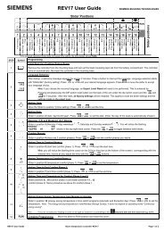
5.3 CONTROL SYSTEMS<br />
DIGITAL CONTROLLER OPERATION<br />
Flow Temp.<br />
Manual operation<br />
Set Point Temp<br />
Control system ready<br />
Modulating valve closing<br />
Modulating valve opening<br />
6<br />
6<br />
Not used<br />
Limit Comparator<br />
Increase value button<br />
Decrease value button<br />
PGM<br />
Program set button<br />
PGM<br />
EXIT<br />
EXIT<br />
Program exit button<br />
WRF 40<br />
DESCRIPTION<br />
The sophisticated digital thermostat controller provides display of water flow temperature, set point temperature<br />
and operating status of the boiler.<br />
TEMPERATURE DISPLAY<br />
The RED display indicates the flow water temperature from the boiler. The GREEN display indicates the boiler<br />
water flow set temperature.<br />
The controller is set to <strong>Hurlcon</strong> factory default settings at the time of manufacture. These settings are suitable for a<br />
wide range of applications but may require fine tuning depending on individual project specifications and<br />
characteristics. A detailed Siemens RWF 40 product manual is available on request which details how all settings<br />
are made and the auto tune function is activated.<br />
Standard settings are as follows<br />
Radiator & Fan Coil System -<br />
Set temp Dead zone High limit<br />
Automatic reset<br />
High Limit<br />
Manual Reset<br />
80 ˚C ± 5 ˚C 85 ˚C 90 ˚C<br />
Inst195 <strong>HM</strong> <strong>Series</strong> <strong>Hydronic</strong> <strong>Boiler</strong> V10_10 13
OPERATION<br />
Sequence of events once the boiler has been correctly installed with the room thermostat and burner turned off.<br />
Event<br />
Turn on electrical power to the boiler<br />
Turn on burner switch.<br />
Turn on room thermostat<br />
Water flow reaches set temperature.<br />
Water flow temperature reaches set<br />
temperature plus 5 ˚C<br />
Water flow temperature falls to set<br />
temperature.<br />
Water flow temperature reaches 90 ˚C<br />
Burner switch turned off<br />
Room thermostat switches off<br />
Room thermostat switches on<br />
Water flow stopped by external control<br />
Water flow is reinstated<br />
Result<br />
Controller powers up and completes test procedure.<br />
Pump starts up.<br />
Flow indicator on.<br />
Ignition sequence begins; checks water flow, high limit and flow<br />
temperature against set temperature. Modulation valve adjusts<br />
gas rate. Ready indicator on<br />
Burner lights.<br />
Burner indicator on.<br />
Modulation valve has reduced gas flow to hold set temperature.<br />
All indicators on<br />
Burner turns off.<br />
Burner indicator off<br />
Modulating gas valves starts to open. Burner relights.<br />
Burner indicator on<br />
High limit switch opens, burner shuts down. Pump continues to<br />
run for preset time.<br />
Burner shuts down, pump continues to run.<br />
Ready indicator off.<br />
Burner shuts down; pump continues to run for preset time.<br />
Ready indicator off.<br />
Pump restarts, burner ignites.<br />
Flow switch de-activates, burner turns off and pump continues<br />
to run for preset time.<br />
Flow indicator off.<br />
Flow switch reactivates, burner re ignites.<br />
Flow indicator on.<br />
5.4 MAINTENANCE<br />
It is recommended that the following items are professionally checked at least every six months and at the<br />
beginning of every heating season.<br />
1. Examine the balanced flue or indoor draught diverter. Make sure there are no obstructions to the flow of<br />
air to, or flue products from, the appliance.<br />
2. Visually check the main burner and pilot flames. If the flame appears yellow, the burner should be cleaned<br />
by a qualified service technician.<br />
3. Keep the boiler area clear and free of combustibles and flammable liquids. Chlorine should not be stored<br />
in the vicinity of the boiler. Chlorine vapours, when drawn through a boiler, can rapidly cause corrosion of<br />
the heat exchanger.<br />
4. Keep the boiler area free from garden refuse and debris. This will help prevent insects nesting in the unit<br />
and ensure extended life and reliability of your boiler.<br />
Inst195 <strong>HM</strong> <strong>Series</strong> <strong>Hydronic</strong> <strong>Boiler</strong> V10_10 14
6.0 GAS CONVERSION<br />
6.1 BURNER CONVERSION<br />
1. Turn off gas supply to unit.<br />
2. Turn off power supply to pump and boiler.<br />
3. Remove front access door<br />
4. Disconnect gas supply from gas valve.<br />
5. Remove the two Phillips head screws from the angle brackets at the end of the manifold tube securing<br />
burner assembly to combustion chamber.<br />
6. Disconnect wiring from gas valve<br />
7. Remove drive motor form gas valve.<br />
8. Slide complete burner tray out through the access opening.<br />
9. Remove the four s/s bolts securing the injector manifold to the burner tray.<br />
10. Remove burner injectors and replace with desired gas type injectors.<br />
11. Remove pilot burner and change pilot injector to desired gas type.<br />
12. Remove regulator screw cap from top of gas valve<br />
13. Turn plastic plug anti-clockwise until fully removed and withdraw spring.<br />
14. Insert spring for desired gas type and re-install plastic plug.<br />
15. Re-install burner assembly and reconnect gas supply.<br />
16. Check gas system for leaks.<br />
17. Commence lighting procedure as described above.<br />
18. Adjust burner pressure as described above.<br />
Natural Gas Propane Gas ULPG Gas<br />
Injector Pilot Burner Injector Pilot Burner Injector Pilot Burner<br />
Model size Size pressure size size pressure size size pressure<br />
200 3.30 mm<br />
N18<br />
silver 0.82 kPa 1.9 mm<br />
N10<br />
black 2.50 kPa 1.9 mm<br />
N10<br />
black 2.00 kPa<br />
250 3.30 mm<br />
N18<br />
silver 0.82 kPa 1.9 mm<br />
N10<br />
black 2.50 kPa 1.9 mm<br />
N10<br />
black 2.00 kPa<br />
300 3.30 mm<br />
N18<br />
silver 0.82 kPa 1.9 mm<br />
N10<br />
black 2.50 kPa 1.9 mm<br />
N10<br />
black 2.00 kPa<br />
N18<br />
N10<br />
N10<br />
400 3.30 mm<br />
500 3.30 mm<br />
silver 0.75 kPa 1.9 mm<br />
N18<br />
silver 0.78 kPa 1.9 mm<br />
black 2.50 kPa 1.9 mm<br />
N10<br />
black 2.50 kPa 1.9 mm<br />
black<br />
N10<br />
black<br />
2.00 kPa<br />
2.00 kPa<br />
Inst195 <strong>HM</strong> <strong>Series</strong> <strong>Hydronic</strong> <strong>Boiler</strong> V10_10 15
6.2 GAS PIPE SIZING TABLES<br />
Natural gas at 1.13 kPa gas meter pressure<br />
VICTORIA<br />
Maximum run of copper pipe with average number of fittings<br />
Model 20 mm 25 mm 32 mm 40 mm 50 mm<br />
<strong>HM</strong> 200 2 m 8 m 30 m 75 m 320 m<br />
<strong>HM</strong> 250 - 6 m 18 m 45 m 220 m<br />
<strong>HM</strong> 300 - 4 m 14 m 35 m 140 m<br />
<strong>HM</strong> 400 - 3 m 8 m 20 m 90 m<br />
<strong>HM</strong> 500 - 1 6 m 14 m 60 m<br />
1.25 kPa gas meter pressure<br />
S.A., W.A., some areas N.S.W.<br />
Maximum run of copper pipe with average number of fittings<br />
Model 20 mm 25 mm 32 mm 40 mm 50 mm<br />
<strong>HM</strong> 200 6 m 25 m 90 m 240 m 320 m<br />
<strong>HM</strong> 250 4 m 18 m 60 m 160 m 320 m<br />
<strong>HM</strong> 300 3 m 14 m 45 m 110 m 320 m<br />
<strong>HM</strong> 400 2 m 8 m 25 m 70 m 300 m<br />
<strong>HM</strong> 500 - 6 m 18 m 45 m 200 m<br />
2.75 kPa gas meter pressure<br />
N.S.W. some areas, some new areas of Victoria.<br />
Maximum run of copper pipe with average number of fittings<br />
Model 15 mm 20 mm 25 mm 32 mm<br />
<strong>HM</strong> 200 4 m 40 m 160 m 320+ m<br />
<strong>HM</strong> 250 3 m 25 m 100 m 320+ m<br />
<strong>HM</strong> 300 2 m 20 m 85 m 280 m<br />
<strong>HM</strong> 400 12 m 50 m 160 m<br />
<strong>HM</strong> 500 8 m 35 m 100 m<br />
7.0 TROUBLESHOOTING<br />
BOILER WILL NOT LIGHT<br />
Possible cause<br />
Remedy<br />
Automatic ignition system fails<br />
Check water flow light indicator.<br />
Pump not running<br />
Check pump and flow switch<br />
Pump air locked<br />
Air bleed system & pump bearing<br />
Flow switch open By pass to test -<br />
Defective gas control<br />
Shut off gas supply and call for service<br />
Thermostat turned off<br />
Turn on<br />
Set temperature lower than water temperature Increase set temperature<br />
Water too hot-fault condition displayed<br />
Refer to fault indication table<br />
High Limit Thermostat open<br />
Reset<br />
Insufficient water flow<br />
Check for too many valves turned off<br />
BOILER MAKING KNOCKING NOISES<br />
Possible cause<br />
Remedy<br />
<strong>Boiler</strong> operating after pump has shut off<br />
Shut off gas supply and call for service<br />
Heat exchanger scaled<br />
Shut off gas supply and call for service<br />
Inst195 <strong>HM</strong> <strong>Series</strong> <strong>Hydronic</strong> <strong>Boiler</strong> V10_10 16
If the boiler cannot be made to perform correctly, please contact the <strong>Hurlcon</strong> Service Office closest to you.<br />
For VICTORIA: Phone (03) 9765 9765<br />
NEW SOUTH WALES: Phone (02) 9674 8544<br />
QUEENSLAND: Phone (07) 3393 3233<br />
SOUTH AUSTRALIA Phone (08) 8345 5755<br />
WEST AUSTRALIA Phone (08) 9258 9322<br />
For all other areas, please contact our Victorian office.<br />
Siemens RWF40 controller program standard settings<br />
To access press and hold PRG for 10 seconds<br />
Process data.<br />
Parameter Display Actual<br />
Settings<br />
Setpoint 1 * SP1 80<br />
Setpoint 2 (optional) * SP2 0<br />
Digital Setpoint Shift (optional) * Dsp 0<br />
Outside Temperature (optional)<br />
Predefinition of external setpoint *<br />
Factory<br />
Setting<br />
Parameter Level.<br />
Parameter Display Factory<br />
Setting<br />
Limit value of limit comparator * AL 0<br />
Switching differential for limit comparator * HySt 0<br />
Proportional band * Pb.1 20<br />
Derivative time dt 30<br />
Integral action time rt 120<br />
Contact spacing * db 2<br />
Actuator running time tt 60<br />
Switch-on threshold burner / stage II * H y S 1 -2<br />
Switch-off threshold stage II * H y S 2 0<br />
Upper switch-off threshold * H y S 3 4<br />
Response threshold q 0<br />
<strong>Heating</strong> curve slope H 4<br />
Parallel displacement * P 0<br />
To access press and hold PRG for 10 seconds for second time<br />
Inst195 <strong>HM</strong> <strong>Series</strong> <strong>Hydronic</strong> <strong>Boiler</strong> V10_10 17<br />
tA<br />
SPE<br />
Configuration Level.<br />
Parameter Display Factory<br />
Setting<br />
Analog input 1, 2 & 3 setpoint changeover / shift C111 9030<br />
Limit comparator: controller type: setpoint 1 locking C112 0010<br />
Unit address decimal place / unit, signal for out-ofrange<br />
C113 0100<br />
Measurement range start analog input 1 * SCL 0<br />
Measurement range end analog input 1 * SCH 100<br />
Measurement range start analog input 2 * SCL2 0<br />
Measurement range end analog input 2 * SCH2 0<br />
Lower setpoint limit * SPL 50<br />
Upper setpoint limit * SPH 85<br />
Actual value correction, analog input 1 * OFF1 0<br />
Actual value correction, analog input 2 * OFF2 0<br />
Actual value correction, analog input 3 * OFF3 0<br />
Filter time constant for digital filter, analog input 1 DF1 1<br />
For OUTDOOR TEMP control refer to wiring diagram.<br />
For NIGHT SETBACK connect D2 and Ground on RWF40 to time clock delaya fully featured PID controllefact
BL<br />
BL<br />
O/A SENSOR<br />
WH<br />
WH<br />
PL<br />
WH<br />
BR<br />
O/A SENSOR<br />
WH<br />
WH<br />
WH<br />
PL<br />
BR<br />
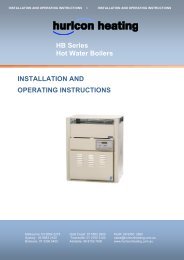
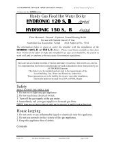
8.0 <strong>HM</strong> SERIES WIRING DIAGRAM<br />
8.1 MODEL 200 – 400<br />
3 LED BOARD<br />
WH<br />
BR<br />
PUMP RUN<br />
ON TIMER<br />
BL<br />
OR<br />
BURNER<br />
ON/OFF<br />
RESET<br />
Q64<br />
M9<br />
WH<br />
FUSE<br />
A<br />
N<br />
E<br />
RD<br />
TRANSFORMER<br />
15 A2<br />
18 B1<br />
A3<br />
BL<br />
WH<br />
GY<br />
RD<br />
OR<br />
Q63<br />
Q14<br />
Q13<br />
B9<br />
XU6<br />
M6<br />
XB6<br />
G1+<br />
HI LIMIT<br />
PL<br />
GY<br />
PL<br />
Y1<br />
Q<br />
U1<br />
M1<br />
SENSOR<br />
3 PIN PLUG<br />
FLOW SWITCH<br />
BR<br />
OR<br />
BL<br />
Y2<br />
N<br />
L1<br />
I1<br />
D2<br />
D1<br />
OR - ORANGE<br />
GY - GREY<br />
BR - BROWN<br />
WH - WHITE<br />
RD - RED<br />
PL - PURPLE<br />
BL - BLUE<br />
PUMP<br />
CONNECTION<br />
A N E<br />
THERMOSTAT OR<br />
PL<br />
GAS<br />
VALVE<br />
OR<br />
G Y1 Y2<br />
MOD GAS VALVE<br />
GND<br />
TE G+<br />
CA G-<br />
CG X1-<br />
CB X1+<br />
RWF40 CONTROLLER<br />
8.2 MODEL 500<br />
3 LED BOARD WH<br />
BR<br />
PUMP RUN<br />
ON TIMER<br />
BL<br />
OR<br />
BURNER<br />
ON/OFF<br />
RESET<br />
Q64<br />
M9<br />
WH<br />
FUSE<br />
A<br />
N<br />
E<br />
RD<br />
TRANSFORMER<br />
15 A2<br />
18 B1<br />
A3<br />
BL<br />
PL<br />
WH<br />
GY<br />
RD<br />
OR<br />
Q63<br />
Q14<br />
Q13<br />
B9<br />
XU6<br />
M6<br />
XB6<br />
G1+<br />
HI LIMIT<br />
PL<br />
GY<br />
PL<br />
Y1<br />
Q<br />
U1<br />
M1<br />
SENSOR<br />
3 PIN PLUG<br />
PUMP<br />
CONNECTION<br />
A N E<br />
THERMOSTAT OR<br />
FLOW SWITCH<br />
OR<br />
6 1 3<br />
9 4 5<br />
2<br />
BR<br />
IGNITION<br />
MODULE<br />
BL<br />
WH<br />
D+<br />
TH<br />
BL<br />
OR<br />
G<br />
Y1<br />
Y2<br />
OR<br />
Y2 I1<br />
N D2<br />
L1 D1<br />
GND<br />
TE G+<br />
CA G-<br />
CG X1-<br />
CB X1+<br />
RWF40 CONTROLLER<br />
OR - ORANGE<br />
GY - GREY<br />
BR - BROWN<br />
WH - WHITE<br />
RD - RED<br />
PL - PURPLE<br />
BL - BLUE<br />
IGNITOR<br />
GAS<br />
VALVE<br />
MOD GAS VALVE<br />
Inst195 <strong>HM</strong> <strong>Series</strong> <strong>Hydronic</strong> <strong>Boiler</strong> V10_10 18
9.0 ONE YEAR LIMITED WARRANTY<br />
GENERAL CONDITIONS<br />
<strong>Hurlcon</strong> cover your boiler with a limited 1 year warranty against defective materials and workmanship from the date<br />
of purchase (plus 30 days to allow for installation). The heat exchanger, including headers are covered by a five<br />
year warranty (plus 30 days to allow for installation). Proof of purchase date must be provided in order to<br />
substantiate warranty claim.<br />
The warranty includes in field labour costs where the boiler is installed in a capital city metropolitan area. Labour<br />
charges apply to boilers installed outside of these areas. Any costs for transport of faulty or replacement parts,<br />
removal or reinstallation are the owner’s responsibility.<br />
<strong>Hurlcon</strong> assumes no liability for consequential damages of any kind.<br />
Like your motor vehicle, your new boiler requires periodic service and maintenance to keep it operating in top<br />
condition and at maximum efficiency. An annual service by one of our qualified service technicians is highly<br />
recommended.<br />
LIMITATIONS<br />
All warranties only apply if the boiler is installed and operated in complete compliance with the installation and<br />
operating instructions. The warranty shall not apply to any boilers or parts that have been subject to accident,<br />
negligence, alteration, abuse or misuse.<br />
ADDITIONAL WARRANTY EXCLUSIONS:<br />
This warranty does not cover failures or malfunctions resulting from:<br />
<br />
<br />
<br />
<br />
<br />
<br />
<br />
Failure to properly install, operate or maintain the boiler in accordance with our printed instructions<br />
provided.<br />
Abuse, alteration, accident, fire, flood and the like. Examples of misuse or neglect include, but are not<br />
limited to, physical damage from external force, not following installation instructions, leaving door off for<br />
extended periods of time, inappropriate application of the boiler, etc.<br />
Scaling, freezing, or other conditions causing an inadequate water circulation.<br />
Incorrect gas pressure or gas supply.<br />
Incorrect or excessive flow rate of water.<br />
Failing to correct bleed water system of air.<br />
Chemical contamination of combustion air or use of chemical additives to the water.<br />
No person is authorised to make any warranties on <strong>Hurlcon</strong>’s behalf. To place a service call, contact your nearest<br />
<strong>Hurlcon</strong> office.<br />
Inst195 <strong>HM</strong> <strong>Series</strong> <strong>Hydronic</strong> <strong>Boiler</strong> V10_10 19
INSTALLATION AND OPERATING INSTRUCTIONS I INSTALLATION AND OPERATING INSTRUCTIONS<br />
HURLCON HEATING Pty. Limited. A.B.N. 97 007 284 504<br />
www.hurlconheating.com.au email: service@hurlconheating.com.au<br />
Information and specifications subject to change without notice.<br />
Victoria: New South Wales: Queensland: South Australia: Western Australia: Gold Coast: Townsville:<br />
Ph: (03) 9554 2275 Ph: (02) 9853 2100 Ph: (07) 3308 5400 Ph: (08) 8152 7600 Ph: (08) 9350 2600 Ph: (07) 5552 2600 Ph: (07) 4750 3100<br />
Fax: (03) 9554 2272 Fax: (02) 98532170 Fax: (07) 3308 5470 Fax: (08) 8152 7670 Fax: (08) 9350 2670 Fax: (07) 5552 2670 Fax: (07) 4750 3170<br />
Inst195 <strong>HM</strong> <strong>Series</strong> <strong>Hydronic</strong> <strong>Boiler</strong> V10_10 20