Hurlcon Gas Fired Hot Water Boiler H120 & H150 ... - Hurlcon Heating
Hurlcon Gas Fired Hot Water Boiler H120 & H150 ... - Hurlcon Heating
Hurlcon Gas Fired Hot Water Boiler H120 & H150 ... - Hurlcon Heating

Create successful ePaper yourself
Turn your PDF publications into a flip-book with our unique Google optimized e-Paper software.
<strong>Hurlcon</strong> <strong>Gas</strong> <strong>Fired</strong><br />
<strong>Hot</strong> <strong>Water</strong> <strong>Boiler</strong><br />
<strong>H120</strong> & <strong>H150</strong> S & B Models<br />
INSTALLATION AND OPERATING INSTRUCTIONS<br />
HURLCON Manufacturing & Sales Pty. Ltd. A.B.N. 97 007 284 504<br />
48 Hanna Street, Noble Park, VICTORIA. 3174<br />
Telephone: (03) 9554 2200 Facsimile: (03) 9554 2270<br />
www.hurlcon.com.au email: service@hurlcon.com.au<br />
Information and specifications subject to change without notice.<br />
Rev 136-1105
INSTALLATION AND OPERATING INSTRUCTIONS ...........................................................1<br />
1.0 INTRODUCTION ...............................................................................................................3<br />
1.1 NOTICE TO INSTALLERS ..................................................................................... 3<br />
2.0 MODELS AVAILABLE .................................................................................................... 4<br />
2.1 STANDARD EQUIPMENT......................................................................................4<br />
3.0 INSTALLATION ...............................................................................................................5<br />
3.1 SAFETY RULES......................................................................................................5<br />
3.2 GUIDE TO INSTALLATION...................................................................................6<br />
3.3 CLEARANCES ........................................................................................................ 7<br />
3.4 ELECTRICAL CONNECTION ................................................................................ 7<br />
3.5 BOILER DIMENSIONS ...........................................................................................8<br />
3.6 INDOOR INSTALLATION......................................................................................8<br />
3.7 VENTILATION – AIR SUPPLY TO THE BOILER.................................................9<br />
3.8 HEATING PIPE SIZE & LAYOUT........................................................................ 10<br />
3.9 SIZING OF PRESSURE VESSEL .......................................................................... 10<br />
4.0 COMMISSIONING ......................................................................................................... 11<br />
4.1 STARTING BOILER.............................................................................................. 11<br />
4.2 TESTING BURNER PRESSURE ........................................................................... 11<br />
4.3 FLOW SWITCH ..................................................................................................... 11<br />
4.4 GENUS IV 3 BUTTON CONTROLLER…………………………………………...12<br />
5.0 OPERATING INSTRUCTIONS ..................................................................................... 12<br />
5.1 ENERGY SAVING TIPS........................................................................................ 13<br />
5.2 MAINTENANCE ................................................................................................... 13<br />
5.3 CONTROL SYSTEMS ........................................................................................... 13<br />
6.0 GAS CONVERSION........................................................................................................ 15<br />
6.1 BURNER CONVERSION ...................................................................................... 15<br />
6.2 GAS – COMPONENT INFORMATION ................................................................ 16<br />
6.3 GAS PIPE SIZING TABLES .................................................................................. 16<br />
7.0 TROUBLESHOOTING ................................................................................................... 17<br />
8.0 <strong>H120</strong> – <strong>H150</strong> WIRING DIAGRAM................................................................................. 18<br />
8.1 MODEL <strong>H120</strong> – <strong>H150</strong> WITH HEATSAVER ........................................................ 18<br />
9.0 ONE YEAR LIMITED WARRANTY............................................................................. 19<br />
<strong>H120</strong> –<strong>H150</strong> <strong>Hot</strong> <strong>Water</strong> <strong>Boiler</strong>s page 2
1.0 INTRODUCTION<br />
Congratulations on your purchase of a <strong>Hurlcon</strong> <strong>H120</strong> - <strong>H150</strong> Series <strong>Hot</strong> <strong>Water</strong> <strong>Boiler</strong>. Correct<br />
installation and service of your new heating system and correct chemical maintenance of the water<br />
will ensure years of service. The <strong>H120</strong> - <strong>H150</strong> Series <strong>Boiler</strong> is a compact lightweight and efficient<br />
gas fired hot water boiler. It is equipped with features that take advantage of new technology<br />
developed exclusively by <strong>Hurlcon</strong>.<br />
The <strong>Hurlcon</strong> <strong>Boiler</strong> is a floor mounted atmospheric boiler with a built in balanced flue for outdoor<br />
installation. The power output is controlled by an integrated electronic controller to maintain the set<br />
point water temperature over a wide load range. In addition, the <strong>Hurlcon</strong> <strong>Boiler</strong> is equipped with<br />
electronic ignition. The electronic display tells at a glance the operational status of the boiler.<br />
1.1 NOTICE TO INSTALLERS<br />
This is a Floor Mounted - External – <strong>Hot</strong> <strong>Water</strong> <strong>Boiler</strong><br />
For use with Natural <strong>Gas</strong> or LP <strong>Gas</strong> as per the attached data label.<br />
The information below is given to assist the installer with the installation of this range of <strong>H120</strong> –<br />
<strong>H150</strong> <strong>Boiler</strong>s. Please read it carefully in order to make the installation as easy as possible and to<br />
ensure the system works well and conforms to the necessary government regulations.<br />
PLEASE READ THESE INSTRUCTIONS BEFORE STARTING THE INSTALLATION.<br />
It is important that this boiler is installed and serviced as detailed in these instructions by an<br />
AUTHORISED person.<br />
This boiler is to be installed and serviced to the requirements of the<br />
Local Building, <strong>Gas</strong>, <strong>Water</strong> and Electricity Authorities.<br />
These instructions are to be held by the owner / user after installation.<br />
This boiler must not be used as a SPA or POOL Heater<br />
This appliance must be installed in accordance with the installation instructions, local gas fitting<br />
regulations, the AGA Installation Code AG 601 and any other relevant statutory authorities.<br />
Refer to data plate for details of gas type, gas consumption and burner pressure.<br />
<strong>H120</strong> –<strong>H150</strong> <strong>Hot</strong> <strong>Water</strong> <strong>Boiler</strong>s page 3
2.0 MODELS AVAILABLE<br />
Details<br />
Model<br />
120S & 120B<br />
Model<br />
150S & 150B<br />
Height 900 900<br />
Length 510 640<br />
Width 390<br />
<strong>Gas</strong> input 105 MJ 144 MJ<br />
<strong>Gas</strong> type<br />
Natural & L P <strong>Gas</strong><br />
Nom output 24 kW (82,000Btu) 35 kW (119,000Btu)<br />
Ignition system<br />
Electronic Ignition<br />
Heat exchanger/burner<br />
All copper/stainless steel<br />
<strong>Boiler</strong> Thermostat<br />
digital Electronic Genus 1V<br />
Pressure relief<br />
300kPa (3 Bar)<br />
Expansion vessel<br />
7 litre diaphragm (~60lt system)*<br />
Circulator<br />
In line Centrifugal Pump*<br />
Hi limit Thermostat<br />
100 o C manual reset<br />
Run on timer<br />
Electronic temperature and time based.<br />
Pressure reduction valve 1 Bar pre-set *<br />
Packed weight 50kg 60kg<br />
2.1 STANDARD EQUIPMENT<br />
Electronic control including.<br />
• Displays set and flow temperature.<br />
• Electronic ignition<br />
Safety devices<br />
• Built in flow switch<br />
• Built in run on timer<br />
• Manual reset high limit<br />
Built to last<br />
• All copper double row heat exchanger<br />
• Stainless steel burners<br />
• Fully powder coated steel cabinet<br />
• Powder coated flue terminal<br />
Efficiency<br />
• <strong>Hot</strong> surface ignition<br />
• Highly efficient stainless steel burners<br />
Ease of installation<br />
• Fully plumbed ready to go, including circulator*, expansion tank*, pressure reduction valve*<br />
& 1” flow – return isolation valves.<br />
• All electrical pre wired including three pin power supply.<br />
(* not supplied with ‘B’ model boiler)<br />
<strong>H120</strong> –<strong>H150</strong> <strong>Hot</strong> <strong>Water</strong> <strong>Boiler</strong>s page 4
3.0 INSTALLATION<br />
THIS APPLIANCE MUST BE INSTALLED BY AN AUTHORISED PERSON.<br />
Refer to boiler data plate for specifications of gas type, gas consumption, burner pressure and water<br />
pressure.<br />
This appliance must be installed in accordance with local regulations and A.G.A. Installation Code<br />
AG 601.<br />
The flow and return connections are located on the rear of the boiler. The flow and return<br />
connections are clearly marked and the connections are 1” BSP FI.<br />
The <strong>Hurlcon</strong> <strong>Boiler</strong> is fitted with a built in flow switch and will not start unless full of water and the<br />
pump is operating.<br />
The <strong>Hurlcon</strong> <strong>Boiler</strong> incorporates a balanced flue terminal and is suitable for outdoor installation. An<br />
internal model is available on request.<br />
3.1 SAFETY RULES<br />
For your safety – read before lighting<br />
This appliance is equipped with an ignition device, which automatically lights the burner. Do not<br />
try to light the burner by hand.<br />
BEFORE OPERATING smell all around the appliance area for gas. Be sure to smell next to the<br />
floor because some gas is heavier than air and will settle on the floor.<br />
Safety<br />
WHAT TO DO IF YOU SMELL GAS<br />
• Do not try to light any gas appliance.<br />
• Do not touch any electrical switch.<br />
• Turn off the gas supply at the gas meter.<br />
• Immediately call your gas supplier or licensed gas fitter.<br />
NOTE. Some gases are heavier than air and it may be necessary to smell for leaks at<br />
floor level.<br />
House keeping<br />
• Do not store or use flammable liquids or chemicals near this appliance.<br />
• Do not use aerosols in the vicinity of this gas appliance.<br />
• Keep this appliance free of debris.<br />
WARNING:<br />
Should overheating occur or the gas supply fail to shut off, turn off the manual gas control valve<br />
to the appliance.<br />
Do not use this boiler if any part has been under water.<br />
<strong>H120</strong> –<strong>H150</strong> <strong>Hot</strong> <strong>Water</strong> <strong>Boiler</strong>s page 5
3.2 GUIDE TO INSTALLATION<br />
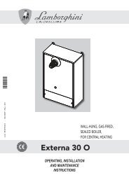
Location of Flue Terminals – An extract from AG 601<br />
Minimum Clearances Required For Balanced Flue Terminals or The Terminals Of Outdoor<br />
Appliances.<br />
a<br />
j<br />
h<br />
T<br />
c<br />
f<br />
n<br />
c<br />
openable<br />
window<br />
I<br />
k<br />
k<br />
j<br />
door<br />
j<br />
h<br />
h<br />
T<br />
g<br />
e<br />
P<br />
e<br />
d<br />
M<br />
d<br />
b<br />
See note 3<br />
g<br />
T<br />
T = Flue terminal<br />
I = Mechanical air inlet<br />
M = <strong>Gas</strong> meter<br />
P = Electricity meter<br />
or fuse box<br />
See note 2<br />
Shading indicates prohibited<br />
areas for flue terminals<br />
A<br />
MIN. CLEARANCE<br />
(mm)<br />
Below eaves, balconies and other projections<br />
Appliances up to 50 MJ/h input 300<br />
Appliances over 50 MJ/h input 500<br />
B From the ground, above a balcony or other surface 300<br />
C From a return wall or external corner 500<br />
D From a gas meter (M) 1000<br />
E From an electricity meter or fuse box (P) 500<br />
F From a drain pipe or soil pipe 150<br />
G Horizontally from any building structure (unless appliance approved 500<br />
for closer installation) or obstruction facing a terminal<br />
H From any other flue terminal, cowl, or combustion air intake 500<br />
I Horizontally from an openable window, door, non-mechanical air inlet, or any 500<br />
other opening into a building with the exception of sub-floor ventilation<br />
Appliances up to 150 MJ/h input 500<br />
Appliances over 150 MJ/h input (natural draught) 1500<br />
Appliances over 200 MJ/h input 1500<br />
All fan-assisted flue appliances, in direction of discharge 1500<br />
K From a mechanical air inlet, including a spa blower 1500<br />
N<br />
Vertically below an openable window, non-mechanical air inlet, or any other<br />
opening into a building with the exception of sub-floor ventilation<br />
See table<br />
Deleted:<br />
Deleted:<br />
Deleted:<br />
Deleted:<br />
Deleted:<br />
Space heaters<br />
Up to 50 MJ/h<br />
input<br />
Up to 50 MJ/h<br />
input<br />
CLEARANCE ‘n’ (mm)<br />
All other appliances<br />
Over 50 MJ/h &<br />
up 150 MJ/h<br />
Over 150 MJ/h<br />
input<br />
150 500 1000 1500<br />
NOTES: 1<br />
All distances are measured to the nearest part of the terminal.<br />
2 Prohibited area below electricity meter or fuse box extends to ground level.<br />
3 See Clause 5.13.6.6 for restrictions on a flue terminal under a covered area.<br />
4 See Appendix J, Figures J1(a) and J2(a), for clearances required from a flue terminal to an LP <strong>Gas</strong> cylinder.<br />
A flue terminal is considered to be a source of ignition.<br />
The above information is part of AG 601 FIGURE 5.3 as supplied by the AGA and is provided as an indication of the<br />
correct clearances only. Please refer to the latest issue of AG 601.<br />
Deleted:<br />
Deleted:<br />
<strong>H120</strong> –<strong>H150</strong> <strong>Hot</strong> <strong>Water</strong> <strong>Boiler</strong>s page 6
3.3 CLEARANCES<br />
The boiler must be installed at least 500mm from any combustible surface. Clearances must comply<br />
with AG 601.<br />
Clearances from non combustible surfaces are:<br />
Front<br />
Both sides<br />
Rear<br />
Above<br />
Combustible Surfaces<br />
500mm<br />
500mm<br />
80mm<br />
1500mm<br />
500mm Minimum<br />
<strong>Boiler</strong> must be installed on a fireproof base.<br />
3.4 ELECTRICAL CONNECTION<br />
The boiler is supplied with a standard 10 amp 3 pin plug for connection to a 240V 10 amp GPO.<br />
The boiler incorporates a 240/24 VAC transformer which supplies power to the control circuit only<br />
and must not be used for any additional equipment. All equipment connected to mains power<br />
should be protected by an RCD circuit breaker. The boiler has a 240 volt power supply for the pump<br />
electrical connection which incorporates the pump run on feature. A terminal strip is provided for a<br />
24 volt room thermostat.<br />
To enable temperature set-back, cut the blue wire loop at the 4 way connector attached to the control<br />
board. Extend the blue wires to a remote switch or timer with volts free contacts. With contacts<br />
closed, Set 1 is enabled. With contacts open, Set is enabled.<br />
If the supply cord is damaged, it must be replaced by the manufacturer or its service agent or a<br />
similarly qualified person in order to avoid a hazard.<br />
3.4.1 GAS CONNECTION<br />
A ¾”BSP FI is provided for gas line connection. An approved manual shut off valve must be<br />
installed in the gas fitting line before the boiler so that the gas can be turned off and the boiler<br />
removed for servicing if required. The gas shut off valve should be sized the same as the gas fitting<br />
line to prevent excessive pressure drop in the gas pipe.<br />
The gas fitting line should be installed by an authorised person and comply with local regulations<br />
and A.G.A. code AG 601. The gas line from the meter will usually be of a larger size than the gas<br />
inlet connection. Therefore a reduction to the boiler connection fitting will be necessary. The<br />
reduction should be as close to the boiler as possible.<br />
Before using the boiler, test all connections for gas leaks using soapy water.<br />
The boiler gas valve has a built in pressure regulator with a ⅛” pressure test point provided. On<br />
starting the boiler, a manometer must be used and burner pressure checked against the boiler data<br />
plate. The gas valve regulator may need adjustment to correct manifold pressure. Incorrect burner<br />
pressure may void warranty.<br />
<strong>H120</strong> –<strong>H150</strong> <strong>Hot</strong> <strong>Water</strong> <strong>Boiler</strong>s page 7
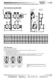
3.5 BOILER DIMENSIONS<br />
Side Plumbing<br />
Front<br />
Side Controls<br />
900<br />
60<br />
70<br />
105 130 130 <strong>H120</strong> – 510<br />
390<br />
<strong>H150</strong> - 640<br />
85<br />
3.6 INDOOR INSTALLATION<br />
Cold feed ½” FI<br />
.<br />
Flow & Return 1” FI<br />
<strong>Gas</strong> inlet ¾” FI<br />
If the <strong>H120</strong> - 150 <strong>Boiler</strong> is to be installed indoors, an indoor draught hood kit must be purchased<br />
from <strong>Hurlcon</strong> and installed on the <strong>Boiler</strong> to convert it to an indoor model.<br />
Product code numbers for draught hoods are:<br />
<strong>Boiler</strong> model Indoor top model Flue size Part number<br />
<strong>H120</strong> DH 12 125 mm 10134<br />
<strong>H150</strong> DH 15 150mm 10970<br />
A flue no smaller than the draught diverter diameter must be installed and terminated with an<br />
approved gas flue cowl (not a Chinaman’s hat) 600mm above any roofline that is within 1.5 metres<br />
horizontally from the flue.<br />
<strong>H120</strong> –<strong>H150</strong> <strong>Hot</strong> <strong>Water</strong> <strong>Boiler</strong>s page 8
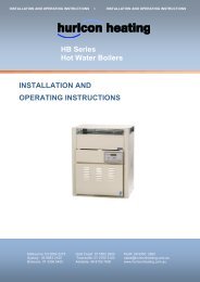
3.7 VENTILATION – AIR SUPPLY TO THE BOILER<br />
When installing the boiler indoors, it is imperative that an adequate supply of fresh air is provided<br />
for combustion. Failure to provide adequate ventilation voids all warranties and may be a danger to<br />
persons or property. Please refer to AG 601 for full details.<br />
Two permanent openings shall be provided directly to outside. The openings shall be located to<br />
ensure the distance between the top of the upper opening and the ceiling of the room or enclosure,<br />
and the distance between the bottom of the lower opening and the floor of the room or enclosure<br />
does not exceed 5% of the height of the room or enclosure.<br />
The minimum vertical dimension of any free ventilation opening shall be 6 mm.<br />
The minimum free ventilation area provided by each opening shall be:<br />
MODELS <strong>H120</strong> <strong>H150</strong><br />
AREA mm 2 35,000 50,000<br />
The following diagram is provided as a guide only. All fluing and installation work must be carried<br />
out by an authorized person. Fluing must conform to local regulations and to A.G.A. installation<br />
code AG 601. Care must be taken to provide the correct ventilation and correct fluing materials in<br />
close proximity to combustible surfaces.<br />
Approved gas<br />
termination cowl<br />
1500<br />
600<br />
Bolted<br />
sleeve to<br />
connect flue<br />
Draft diverter<br />
purchased<br />
from <strong>Hurlcon</strong><br />
Upper grille for fresh<br />
air ventilation<br />
Lower grille for fresh<br />
air ventilation<br />
A <strong>Hurlcon</strong> indoor draught diverter must be fitted to unit in accordance with <strong>Hurlcon</strong>’s<br />
Instructions and Installation Codes before the boiler can be enclosed.<br />
Do not install spa blowers in the same room as a gas boiler. This is potentially dangerous to<br />
spa users.<br />
Do not store chemicals or fuel in the same room as the gas boiler. This may cause fire or<br />
explosion.<br />
When installing in a garage the <strong>H120</strong> – 150 <strong>Boiler</strong> must be installed 450 mm above floor level.<br />
<strong>H120</strong> –<strong>H150</strong> <strong>Hot</strong> <strong>Water</strong> <strong>Boiler</strong>s page 9
3.8 HEATING PIPE SIZE & LAYOUT<br />
• The flow & return connection sizes of 1”BSP on the boiler are not necessarily the correct<br />
pipe sizes for the heating system. It is important that the pipe sizes are correctly calculated<br />
before installation.<br />
• <strong>Hurlcon</strong> recommend a two pipe system with the pipes sized according to the flow<br />
requirements and length of runs with a maximum water velocity of 1.5 M/s.<br />
• Reference The Institute of Plumbing Australia. - “SELECTION & SIZING OF COPPER<br />
TUBES FOR PIPING SYSTEMS”.<br />
Nominal flow capacities<br />
Model Output Flow rates DT pd min Pipe dia F & R length<br />
120 24 kW 0.38 l/s 15 °C 8 kPa 20 mm 6.0 m<br />
150 35 kW 0.53 l/s 15 °C 14 kPa 25 mm 4.5 m<br />
Typical two pipe system<br />
Radiator/Heat emitter<br />
Flow Flow Flow<br />
Hydronic <strong>Boiler</strong><br />
Return<br />
Bypass valve<br />
Notes<br />
1. An automatic heating bypass valve should be fitted to maintain adequate flow rate through the<br />
boiler when thermostatic valves are fitted and or when the majority of radiators are required to be<br />
turned off for long periods of time.<br />
2. Any pipe work that is in an unheated area such as under the floor or in the ceiling space should be<br />
suitably insulated to prevent heat loss and possible freezing of the pipes.<br />
3. The pipe work should be graded to facilitate the elimination of air at the highest point and the<br />
draining of the system at the lowest point. Provide air bleeds and drains at these points.<br />
3.9 SIZING OF PRESSURE VESSEL<br />
If the total water capacity of the heating<br />
system is greater than 60 litres then an<br />
additional pressure vessel should be fitted.<br />
An approximate figure can be calculated<br />
from the following table. An additional<br />
tank can be fitted at a convenient location<br />
on the system if required.<br />
Item<br />
Capacity per<br />
litres<br />
Therma rad Radiators 0.70 kW<br />
Thermaboard single 0.22 metre<br />
Thermaboard double 0.44 metre<br />
Copper tube 25 mm 0.44 metre<br />
Copper tube 20 mm 0.23 metre<br />
Copper tube 15 mm 0.10 metre<br />
<strong>H120</strong> –<strong>H150</strong> <strong>Hot</strong> <strong>Water</strong> <strong>Boiler</strong>s page 10
4.0 COMMISSIONING<br />
4.1 STARTING BOILER<br />
• Fill system with water and purge all air from system and pump.<br />
• Purge gas line of any air and wait five minutes for gas to clear.<br />
• Plug three pin plug into a suitable power point and switch on. Digital controller should now<br />
operate and indicate water temperature.<br />
• Pump should start, the flow symbol should be displayed.<br />
• Turn controller switch ON.<br />
• After a few seconds, the burner should ignite. (Do not light by any other means.)<br />
• If the burner fails to light, check flow indicator is on. Turn controller switch OFF for 5<br />
seconds then ON to reset ignition system. (Trouble shooting page 19.)<br />
• Allow boiler to run. Check there are no leaks and there is flow to all of system.<br />
4.2 TESTING BURNER PRESSURE<br />
• Set up manometer<br />
• Turn boiler “OFF”.<br />
• Remove screw from ⅛” brass test point located on outlet side of gas valve.<br />
• Connect manometer tube to test point<br />
• Turn boiler “ON” and wait for main burner to ignite.<br />
• Once main burner has ignited, the manometer must indicate the nominal burner pressure<br />
listed below.<br />
• To adjust gas valve regulator, remove regulator adjustment cap and, using a screwdriver, turn<br />
plastic bush clockwise to increase, anti-clockwise to decrease burner pressure.<br />
• Check all gas connections are tight and not leaking.<br />
Maximum inlet gas pressure is:<br />
Natural <strong>Gas</strong> 3.5 kPa Propane <strong>Gas</strong> 3.5 kPa ULPG 3.5 kPa<br />
Nominal burner pressure is:<br />
<strong>H120</strong> <strong>H150</strong><br />
Natural <strong>Gas</strong> kPa 0.82 0.82<br />
Propane <strong>Gas</strong> kPa 2.50 2.50<br />
ULPG kPa 2.00 2.00<br />
4.3 FLOW SWITCH<br />
• The <strong>Hurlcon</strong> <strong>Boiler</strong> has an inbuilt flow switch which allows the burner to operate only when<br />
the system is full of water and the circulating pump is operating. NOTE: The installed flow<br />
switch has no user adjustments.<br />
• Air in the system may stop the boiler from lighting.<br />
<strong>H120</strong> –<strong>H150</strong> <strong>Hot</strong> <strong>Water</strong> <strong>Boiler</strong>s page 11
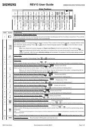
4.4 GENUS IV 3 BUTTON CONTROLLER<br />
• 90° or 55° operation. H series boilers are set factory default 90°. For floor heat<br />
applications the boiler can be selected for 55° max setpoint by a jumper on the PCB. (See<br />
page 18).<br />
• <strong>Hurlcon</strong> Genus IV room thermostat. If a <strong>Hurlcon</strong> Genus IV room thermostat is fitted the<br />
Genus boiler control will ‘learn’ automatically when powered up after approx 1 minute. If<br />
the thermostat is disconnected or loses communication F5 fault will be displayed and the<br />
boiler will shut down after 3 minutes. To change thermostat type see table below. The<br />
thermostat selector switch will also need to be set, see page 18.<br />
• Switching differential. The temperature switching differential can be adjusted to stop short<br />
cycling. See table below for appropriate codes. (Default 5°.)<br />
• °F or °C. The display can be toggled between Celsius and Fahrenheit. See table below for<br />
codes. (Default °C.)<br />
With the unit switched off, press and hold the on/off button then press the following.<br />
Button presses<br />
1 2 3 4<br />
Degrees C U D D D<br />
Degrees F U D D U<br />
Genus IV thermostat U D U D<br />
Standard thermostat U D U U<br />
5 ° differential D D D U<br />
10 ° differential D D U D<br />
15 ° differential D D U U<br />
20 ° differential D U D D<br />
U = warm button D = cool button<br />
5.0 OPERATING INSTRUCTIONS<br />
• STOP! Read the safety rules on page 5 section 3.1.<br />
• Turn off electric power to appliance.<br />
• This appliance is equipped with an ignition device, which automatically lights the burner.<br />
Do not try to light the burner by hand.<br />
• Wait five minutes to clear out any gas. If you then smell gas, STOP! Refer to instructions<br />
above.<br />
• Turn on power to appliance.<br />
• Set thermostat to desired setting and press ON/OFF switch to ON. The boiler will ignite in<br />
around 10 seconds<br />
• If the appliance will not operate, press ON/OFF switch to OFF then ON again. If the<br />
appliance still does not ignite, check trouble shooting on page 19 or call your service<br />
technician.<br />
TO TURN GAS OFF TO APPLIANCE<br />
• Turn off all electrical power to the appliance.<br />
• Turn off gas tap in gas line prior to boiler.<br />
<strong>H120</strong> –<strong>H150</strong> <strong>Hot</strong> <strong>Water</strong> <strong>Boiler</strong>s page 12
5.1 ENERGY SAVING TIPS<br />
• During extended periods of non use, turn the boiler off.<br />
• Set up a regular program of preventative maintenance for the boiler. Check heat exchanger,<br />
controls, burner operation etc.<br />
• For areas where there is a danger of freezing, water should circulate through your boiler even<br />
if the heating is off.<br />
5.2 MAINTENANCE<br />
• It is recommended that the following items are professionally checked at least every six<br />
months and at the beginning of every heating season.<br />
• Examine the balanced flue or indoor draught diverter. Make sure there are no obstructions to<br />
the flow of air to, or flue products from, the appliance.<br />
• Visually check the main burner and pilot flames. If the flame appears yellow, the burner<br />
should be cleaned by a qualified service technician.<br />
• Keep the boiler area clear and free of combustibles and flammable liquids. Chlorine should<br />
not be stored in the vicinity of the boiler. Chlorine vapours, when drawn through a boiler,<br />
can rapidly cause corrosion of the heat exchanger.<br />
• Keep the boiler area free from garden refuse and debris. This will help prevent insects<br />
nesting in the unit and ensure extended life and reliability of your boiler.<br />
5.3 CONTROL SYSTEMS<br />
HURLCON<br />
○<br />
><br />
<<br />
ON/OFF WARM COOL<br />
HURLCON<br />
5.3.1 DESCRIPTION<br />
The sophisticated digital thermostat provides temperature read out, set point temperature and<br />
operating status of the boiler. The electronic display indicates the operational status of the boiler<br />
and any fault conditions.<br />
5.3.2 TEMPERATURE DISPLAY<br />
• The temperature display indicates water temperature in the outlet (flow) of the boiler.<br />
Therefore the pump must be operating for an accurate water temperature to be displayed.<br />
• <strong>Water</strong> temperature can be set between 55˚C to 90˚C. (35˚C to 55˚C floor heat). To select<br />
your desired water temperature press the up or down button repeatedly until the desired<br />
temperature is reached.<br />
• Fitting of an external switch allows temperature set-back via two adjustable set points. (See<br />
section<br />
<strong>H120</strong> –<strong>H150</strong> <strong>Hot</strong> <strong>Water</strong> <strong>Boiler</strong>s page 13
• To prevent rapid cycling of the boiler, the thermostat has an inbuilt time delay which<br />
prevents the boiler from turning on for two minutes after the set point has been reached. If<br />
the time delay is activated, the symbol “L” will be displayed. This is part of normal<br />
operation.<br />
• The thermostat can be set to temperatures between 55˚C to 90˚C. (35˚C to 55˚C floor heat).<br />
It also incorporates several safety features including a 100˚C high limit function to prevent<br />
overheating. On simultaneous shut down of the circulating pump and boiler, the water within<br />
the boiler may exceed the set temperature for a short period. If the pump and boiler are<br />
restarted during this period, the thermostat will go into a standby mode and prevent the boiler<br />
from relighting until the temperature within the boiler has dropped below the set<br />
temperature.<br />
• If the optional set-back function is used, both set points (Set, Set 1) need to be adjusted<br />
independently. These are each adjustable over the full thermostat range.<br />
• Should the thermostat fail to stop the boiler at the set point or at 100˚C, there is a manual<br />
reset temperature limiting safety device designed to lock the boiler out and prevent further<br />
heating. Plus a lock out condition is indicated by the symbols F1 or F2. To reset a lock out<br />
condition, turn the controller off for five seconds. An F2 condition will first require the<br />
mechanical safety device to be reset. To do this, remove the rear access panel and press the<br />
red button. If the boiler has cooled sufficiently, a positive “click” should be heard and felt.<br />
5.3.3 FAULT INDICATION<br />
Under fault conditions the thermostat display will indicate a set of alpha numeric symbols to<br />
indicate the status of the boiler. The meaning of each symbol and action to be taken are listed as<br />
follows:<br />
SYMBOL MEANING ACTION<br />
Temp Unit has power.<br />
No action<br />
Display<br />
F0 <strong>Boiler</strong> locked off, thermistor wire is<br />
disconnected or water at 0°C<br />
If water temperature reads greater than 0°C, turn<br />
off/on if problem persists phone for service.<br />
(freeze conditions).<br />
F1 Thermostat reads greater than<br />
100°C or thermistor short circuited.<br />
Allow water to cool, turn boiler off then on<br />
again.<br />
F2 Mechanical Hi Limit greater than<br />
100°C.<br />
Allow water to cool, reset Hi Limit, turn boiler<br />
off then on again.<br />
F5 Thermostat communication fault Check connections. Check thermostat ‘type’<br />
setting is correct.<br />
L <strong>Boiler</strong> locked out on time delay No action. <strong>Boiler</strong> will delay for 2 minutes<br />
Automatically reset after time delay. Or switch<br />
Pump operating & sufficient water<br />
flow to operate boiler<br />
off then on again for immediate ignition.<br />
No action.<br />
Thermostat calling for heat<br />
operating.<br />
No action, boiler electronic ignition should<br />
ignite in a few seconds.<br />
Burner system has ignited and is<br />
operating.<br />
No action.<br />
<strong>H120</strong> –<strong>H150</strong> <strong>Hot</strong> <strong>Water</strong> <strong>Boiler</strong>s page 14
5.3.4 OPERATION<br />
Sequence of events once the boiler has been correctly installed with the room thermostat and burner<br />
turned off.<br />
Event<br />
Turn on electrical power to the boiler<br />
Turn on room thermostat<br />
Turn controller on.<br />
<strong>Water</strong> flow reaches set temperature.<br />
<strong>Water</strong> flow temperature falls 5°C<br />
below set temperature.<br />
<strong>Water</strong> flow temperature reaches 100°C<br />
Controller turned off<br />
Room thermostat switches off<br />
Room thermostat switches on<br />
<strong>Water</strong> flow stopped by external control<br />
<strong>Water</strong> flow is reinstated<br />
Result<br />
Controller powers up and completes test procedure.<br />
Pump starts up. Flow indicator on.<br />
Ignition sequence begins; checks water flow, high limit<br />
and flow temperature against set temperature.<br />
Burner lights.<br />
Burner indicator on.<br />
Burner turns off.<br />
Burner relights.<br />
Burner indicator on.<br />
High limit switch opens, burner shuts down. Pump<br />
continues to run.<br />
Burner shuts down, pump continues to run.<br />
Burner shuts down, pump continues to run till water<br />
temperature drops to 40˚C.<br />
Pump restarts, burner ignites.<br />
Flow switch de-activates, burner turns off and pump<br />
continues to run.<br />
Flow indicator off.<br />
Flow switch reactivates, burner re ignites.<br />
Flow indicator on.<br />
6.0 GAS CONVERSION<br />
6.1 BURNER CONVERSION<br />
<strong>Gas</strong> type burner conversion<br />
• Turn off the gas at the external gas valve and turn off the power.<br />
• Remove the access panels from all available sides.<br />
• Disconnect internal gas pipe from inlet side of gas valve.<br />
• Remove the four screws holding the burner assembly in position.<br />
• Disassemble burner tray and remove ribbon burners to expose burner injectors.<br />
• Remove burner injectors and replace with the correct sized injectors for the gas.<br />
• Remove regulator screw cap from top of gas valve.<br />
• Turn plastic plug anti-clockwise until fully removed and withdraw spring.<br />
• Insert spring for desired gas type and re-install plastic plug.<br />
• Re-install burner assembly and reconnect gas supply make sure all gas joints are tight<br />
and the earth screw is replaced.<br />
• Check gas system for leaks.<br />
• Commence lighting procedure as described above.<br />
• Adjust burner pressure as described above.<br />
<strong>H120</strong> –<strong>H150</strong> <strong>Hot</strong> <strong>Water</strong> <strong>Boiler</strong>s page 15
6.2 GAS – COMPONENT INFORMATION<br />
Natural <strong>Gas</strong> Propane <strong>Gas</strong> ULPG <strong>Gas</strong><br />
Injector Burner Injector Burner Injector Burner<br />
Model size pressure size pressure size pressure<br />
<strong>H120</strong> 1.25mm 0.90 kPa 0.75mm 2.50 kPa 0.75mm 2.00 kPa<br />
<strong>H150</strong> 1.25mm 0.90 kPa 0.75mm 2.50 kPa 0.75mm 2.00 kPa<br />
6.3 GAS PIPE SIZING TABLES<br />
Natural gas at 1.13 kPa gas meter pressure<br />
VICTORIA<br />
Maximum run of copper pipe with average number of fittings<br />
Model 20 mm 25 mm 32 mm 40 mm 50 mm<br />
<strong>H120</strong> 4 m 25 m 90 m 260 m 320 m<br />
<strong>H150</strong> 2 m 14 m 50 m 140 m 320m<br />
1.25 kPa gas meter pressure<br />
S.A., W.A., some areas N.S.W.<br />
Maximum run of copper pipe with average number of fittings<br />
Model 20 mm 25 mm 32 mm 40 mm 50 mm<br />
<strong>H120</strong> 18 m 85 m 300 m 320 m -<br />
<strong>H150</strong> 10 m 45 m 160 m 320 m -<br />
2.75 kPa gas meter pressure<br />
N.S.W. some areas, some new areas of Victoria.<br />
Maximum run of copper pipe with average number of fittings<br />
Model 15 mm 20 mm 25 mm 32 mm<br />
<strong>H120</strong> 12 m 100 m 320 +m -<br />
<strong>H150</strong> 8 m 65 m 260 m 320 +m<br />
NO allowance has been made for other appliances connected to the gas main. This<br />
information is supplied as an indication of the capacities only. Refer to the latest issue of<br />
AG601 for full details.<br />
<strong>H120</strong> –<strong>H150</strong> <strong>Hot</strong> <strong>Water</strong> <strong>Boiler</strong>s page 16
7.0 TROUBLESHOOTING<br />
BOILER WILL NOT LIGHT<br />
Possible cause<br />
Remedy<br />
Automatic ignition system fails<br />
Check water flow light indicator.<br />
Pump not running<br />
Check pump and flow switch<br />
Pump air locked<br />
Air bleed system & pump bearing<br />
Flow switch open<br />
Check continuity<br />
Defective gas control<br />
Shut off gas supply and call for service<br />
Thermostat turned off<br />
Turn on<br />
Set temperature lower than water temperature Increase set temperature<br />
<strong>Water</strong> too hot-fault condition displayed Refer to fault indication table<br />
High Limit Thermostat open<br />
Reset<br />
Insufficient water flow<br />
Check for too many valves turned off<br />
BOILER MAKING KNOCKING NOISES<br />
Possible cause<br />
Remedy<br />
<strong>Boiler</strong> operating after pump has shut off Shut off gas supply and call for service<br />
Heat exchanger scaled<br />
Shut off gas supply and call for service<br />
If the boiler cannot be made to perform correctly, please contact the <strong>Hurlcon</strong> Service Office closest<br />
to you.<br />
For VICTORIA: Phone (03) 9765 9765<br />
NEW SOUTH WALES: Phone (02) 9674 8544<br />
QUEENSLAND: Phone (07) 3393 3233<br />
SOUTH AUSTRALIA Phone (08) 8345 5755<br />
WESTERN AUSTRALIA Phone (08) 9258 9322<br />
For all other areas, please contact our Victorian office.<br />
<strong>H120</strong> –<strong>H150</strong> <strong>Hot</strong> <strong>Water</strong> <strong>Boiler</strong>s page 17
8.0 <strong>H120</strong> – <strong>H150</strong> WIRING DIAGRAM<br />
8.1 MODEL <strong>H120</strong> – <strong>H150</strong> WITH HEATSAVER<br />
8.2 55 – 90 DEGREE SETTING & THERMOSTAT SELECTION<br />
By changing the jumper position the boiler<br />
maximum setpoint can be altered from 90° to<br />
55°. This should be done prior to start up,<br />
however if this is done after power has been<br />
applied to the boiler un- plugging and<br />
reconnecting power will ensure the correct<br />
setting. This is located on the rear of the<br />
Genus control board at the front of the <strong>Boiler</strong>.<br />
If the optional <strong>Hurlcon</strong> Genus room<br />
thermostat is used the thermostat selector<br />
switch is required to be set to the correct<br />
position. This switch is located at the rear of<br />
the electrical panel within the boiler cabinet as<br />
shown.<br />
<strong>H120</strong> –<strong>H150</strong> <strong>Hot</strong> <strong>Water</strong> <strong>Boiler</strong>s page 18
9.0 ONE YEAR LIMITED WARRANTY<br />
GENERAL CONDITIONS<br />
<strong>Hurlcon</strong> cover your boiler with a limited 1 year warranty against defective materials and<br />
workmanship from the date of purchase (plus 30 days to allow for installation). The heat<br />
exchanger, burner and cabinet are covered by a five year limited warranty (plus 30 days to allow for<br />
installation). Proof of purchase date must be provided in order to substantiate warranty claim.<br />
The warranty includes in field labour costs where the boiler is installed in a capital city metropolitan<br />
area. Labour charges apply to boilers installed outside of these areas. Any costs for transport of<br />
faulty or replacement parts, removal or reinstallation are the owner’s responsibility.<br />
<strong>Hurlcon</strong> assumes no liability for consequential damages of any kind.<br />
Like your motor vehicle, your new boiler requires periodic service and maintenance to keep it<br />
operating in top condition and at maximum efficiency. An annual service by one of our qualified<br />
service technicians is highly recommended.<br />
LIMITATIONS<br />
All warranties only apply if the boiler is installed and operated in complete compliance with the<br />
installation and operating instructions. The warranty shall not apply to any boilers or parts that<br />
have been subject to accident, negligence, alteration, abuse or misuse.<br />
ADDITIONAL WARRANTY EXCLUSIONS:<br />
This warranty does not cover failures or malfunctions resulting from:<br />
• Failure to properly install, operate or maintain the boiler in accordance with our printed<br />
instructions provided.<br />
• Abuse, alteration, accident, fire, flood and the like. Examples of misuse or neglect include,<br />
but are not limited to, physical damage from external force, not following installation<br />
instructions, leaving door off for extended periods of time, inappropriate application of the<br />
boiler, etc.<br />
• Scaling, freezing, or other conditions causing an inadequate water circulation.<br />
• Incorrect gas pressure or gas supply.<br />
• Incorrect or excessive flow rate of water.<br />
• Failing to correctly bleed water system of air.<br />
• Chemical contamination of combustion air or use of chemical additives to the water.<br />
• Printed Circuit Boards: This item is warranted against all claims except for power surges,<br />
lightening strikes, wilful damage or water damage<br />
No person is authorised to make any warranties on <strong>Hurlcon</strong>’s behalf.<br />
contact your nearest <strong>Hurlcon</strong> office.<br />
To place a service call,<br />
<strong>Hurlcon</strong> Manufacturing & Sales Pty. Limited<br />
Victoria:<br />
Ph: (03) 9554 2275<br />
Fax: (03) 9554 2272<br />
New South Wales:<br />
Ph: (02) 9674 8544<br />
Fax: (02) 9674 8522<br />
Queensland:<br />
Ph: (07) 3393 3233<br />
Fax: (07) 3393 3255<br />
Website: www.hurlcon.com.au<br />
Email: service@hurlcon.com.au<br />
South Australia:<br />
Ph: (08) 8345 5755<br />
Fax: (08) 8345 5211<br />
Western Australia:<br />
Ph: (08) 9258 9322<br />
Fax: (08) 9258 9344<br />
<strong>H120</strong> –<strong>H150</strong> <strong>Hot</strong> <strong>Water</strong> <strong>Boiler</strong>s page 19