HW130 & HW160 Outdoor Modulating Boiler.pdf - Hurlcon Heating
HW130 & HW160 Outdoor Modulating Boiler.pdf - Hurlcon Heating
HW130 & HW160 Outdoor Modulating Boiler.pdf - Hurlcon Heating

You also want an ePaper? Increase the reach of your titles
YUMPU automatically turns print PDFs into web optimized ePapers that Google loves.
INSTALLATION AND OPERATING INSTRUCTIONS I INSTALLATION AND OPERATING INSTRUCTIONS<br />
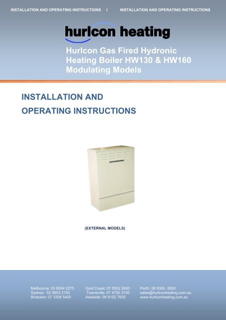
<strong>Hurlcon</strong> Gas Fired Hydronic<br />
<strong>Heating</strong> <strong>Boiler</strong> <strong>HW130</strong> & <strong>HW160</strong><br />
<strong>Modulating</strong> Models<br />
INSTALLATION AND<br />
OPERATING INSTRUCTIONS<br />
(EXTERNAL MODELS)<br />
Melbourne: 03 9554 2275 Gold Coast: 07 5552 2600 Perth: 08 9350 2600<br />
Sydney: 02 9853 2100 Townsville: 07 4750 3100 sales@hurlconheating.com.au<br />
Brisbane: 07 3308 5400 Adelaide: 08 8152 7600 www.hurlconheating.com.au<br />
2/06/2010
INDEX<br />
INTRODUCTION……………………………………………………………………………………… 3<br />
NOTICE TO INSTALLERS…………………………………………………………………………... 3<br />
MODELS AVAILABLE………………………………………………………………………………... 4<br />
STANDARD EQUIPMENT…………………………………………………………………………… 4<br />
INSTALLATION……………………………………………………………………………………….. 5<br />
SAFETY RULES………………………………………………………………………………………. 5<br />
GUIDE TO INSTALLATION………………………………………………………………………….. 6<br />
CLEARANCES………………………………………………………………………………………… 7<br />
ELECTRICAL CONNECTION……………………………………………………………………….. 7<br />
BOILER DIMENSIONS……………………………………………………………………………….. 8<br />
INDOOR INSTALLATION……………………………………………………………………………. 8<br />
HEATING PIPE SIZE & LAYOUT……………………………………………………………………. 8<br />
SIZING OF PRESSURE VESSEL…………………………………………………………………… 9<br />
COMMISSIONING…………………………………………………………………………………….. 9<br />
STARTING BOILER…………………………………………………………………………………… 9<br />
TESTING BURNER PRESSURE……………………………………………………………………. 10<br />
FLOW SWITCH ……………………………………………………………………………………….. 11<br />
CENTRAL HEATING CONTROLLER …………………………………….…………...……………. 12<br />
OPERATING INSTRUCTIONS………………………………………………………………………. 12<br />
ENERGY SAVING TIPS………………………………………………………………………………. 12<br />
MAINTENANCE………………………………………………………………………………………... 13<br />
CENTRAL HEATING THERMOSTAT INSTRUCTIONS . . …………….. . . . . . . . . .. . . . . . . 13<br />
GAS CONVERSION……………………………………………………………………………………. 14<br />
................................................................................................................................................... 15<br />
BURNER CONVERSION……………………………………………………………………………… 15<br />
……………………………………………………………………………………………………………. 16<br />
GAS PIPE SIZING TABLES…………………………………………………………………………… 17<br />
TROUBLESHOOTING…………………………………………………………………………………. 18<br />
<strong>HW130</strong> – <strong>HW160</strong> WIRING DIAGRAM……………………………………………………………….. 19<br />
ONE YEAR LIMITED WARRANTY…………………………………………………………………… 20<br />
MOUNTING INSTRUCTIONS ………………………………………………………...………...…... 21<br />
<strong>HW130</strong> & <strong>HW160</strong> <strong>Modulating</strong> <strong>Boiler</strong> 2
INTRODUCTION<br />
Congratulations on your purchase of a <strong>Hurlcon</strong> <strong>HW130</strong> - <strong>HW160</strong> Series <strong>Modulating</strong> Hot Water <strong>Boiler</strong>. Correct<br />
installation and service of your new heating system and correct chemical maintenance of the water will ensure<br />
years of service. The <strong>HW130</strong> - <strong>HW160</strong> Series <strong>Boiler</strong> is a compact lightweight and efficient gas fired hot water<br />
boiler.<br />
The <strong>Hurlcon</strong> HW <strong>Boiler</strong> is a wall mounted induced draught atmospheric boiler with inbuilt flue for outdoor<br />
operation. The power output is controlled by an integrated electronic controller to maintain the set point water<br />
temperature over a wide load range. In addition, the <strong>Hurlcon</strong> HW <strong>Boiler</strong> is equipped with electronic ignition. The<br />
room thermostat display tells at a glance the operational status of the boiler. The boiler application (radiator or<br />
floor coil) is selectable via jumper settings on the boiler controller.<br />
Note:<br />
The appliance is not intended for use by young children or infirm person without supervision. Please ensure that<br />
young children are supervised to ensure that they do not play with the appliance.<br />
NOTICE TO INSTALLERS<br />
This is a Wall Mounted - External – Hot Water <strong>Heating</strong> <strong>Boiler</strong><br />
For use with Natural Gas or LP Gas as per the attached data label.<br />
The information below is given to assist the installer with the installation of this range of <strong>HW130</strong> – <strong>HW160</strong> <strong>Boiler</strong>s.<br />
Please read it carefully in order to make the installation as easy as possible and to ensure the system works well<br />
and conforms to the necessary government regulations.<br />
PLEASE READ THESE INSTRUCTIONS BEFORE STARTING THE INSTALLATION.<br />
THIS APPLIANCE MUST BE INSTALLED BY AN AUTHORISED PERSON ONLY.<br />
This boiler is to be installed and serviced to the requirements of the<br />
Local Building, Gas, Water and Electricity Authorities.<br />
These instructions are to be held by the owner / user after installation.<br />
THIS APPLIANCE IS UNSUITABLE FOR USE AS A POOL HEATER<br />
This appliance must be installed in accordance with the installation instructions, local gas fitting regulations, the<br />
AGA Installation Code AS5601 / AG 601 and any other relevant statutory authorities.<br />
Refer to data plate for details of gas type, gas consumption and burner pressure.<br />
<strong>HW130</strong> & <strong>HW160</strong> <strong>Modulating</strong> <strong>Boiler</strong> 3
MODELS AVAILABLE<br />
Details<br />
Model<br />
<strong>HW130</strong> <strong>Modulating</strong><br />
Model<br />
<strong>HW160</strong> <strong>Modulating</strong><br />
Height 905<br />
Width 520 651<br />
Depth 325<br />
Gas input 105.5 (95) MJ 145 (135) MJ<br />
Gas type<br />
Natural & (L P Gas)<br />
Nom output 24 (21) kW 35 (32) kW<br />
Ignition system<br />
Electronic Ignition<br />
Heat exchanger/burner<br />
All copper/stainless steel<br />
<strong>Boiler</strong> Thermostat<br />
SIT (modulating)<br />
Pressure relief<br />
300kPa (3 Bar)<br />
Expansion vessel<br />
7 litre diaphragm (~60lt system)<br />
Circulator<br />
In line Centrifugal Pump<br />
Hi limit Thermostat<br />
99 o C<br />
Run on timer<br />
Timed electronic<br />
Pressure reduction valve<br />
1 Bar pre-set<br />
Packed weight 50kg 60kg<br />
STANDARD EQUIPMENT<br />
Electronic boiler control with linking room thermostat.<br />
Set temperature display.<br />
Electronic ignition<br />
Safety devices<br />
Built in flow switch<br />
Manual reset high limit<br />
Built in pressure relief valve<br />
Built to last<br />
Double row heat exchanger made from one piece extruded finned copper tube<br />
Stainless steel burners<br />
Fully powder coated steel cabinet<br />
Stainless steel flue terminal<br />
Efficiency<br />
Hot surface ignition<br />
Induced draught combustion<br />
Highly efficient stainless steel burners<br />
<strong>Modulating</strong> input gas burner<br />
Ease of installation<br />
Fully plumbed ready to go, including circulating pump, expansion tank, pressure reduction valve & 1” flow<br />
and return isolation valves.<br />
All electrical pre wired including three pin plug.<br />
<strong>HW130</strong> & <strong>HW160</strong> <strong>Modulating</strong> <strong>Boiler</strong> 4
INSTALLATION<br />
THIS APPLIANCE MUST BE INSTALLED BY AN AUTHORISED PERSON.<br />
Refer to boiler data plate for specifications of gas type, gas consumption, burner pressure and water pressure.<br />
This appliance must be installed in accordance with local regulations and A.G.A. Installation Code AS5601 / AG<br />
601.<br />
The flow and return connections are located on the bottom of the boiler. The flow and return connections are<br />
clearly marked and the connections are 1” BSP FI.<br />
The <strong>Hurlcon</strong> <strong>Boiler</strong> is fitted with a built in flow switch and will not start unless full of water and the pump is<br />
operating.<br />
The <strong>Hurlcon</strong> <strong>Boiler</strong> incorporates a powered flue terminal suitable for outdoor installation. An indoor room sealed<br />
model combined with co-axial flue kit for internal installation is available on request.<br />
SAFETY RULES<br />
For your safety – read before lighting<br />
This appliance is equipped with an ignition device, which automatically lights the burner. Do not try to light the<br />
burner by hand.<br />
BEFORE OPERATING smell all around the appliance area for gas. Be sure to smell next to the floor because<br />
some gas is heavier than air and will settle on the floor.<br />
Safety<br />
WHAT TO DO IF YOU SMELL GAS<br />
Do not try to light any gas appliance.<br />
Do not touch any electrical switch.<br />
Turn off the gas supply at the gas meter.<br />
Immediately call your gas supplier or licensed gas fitter.<br />
NOTE. Some gases are heavier than air and it may be necessary to smell for leaks at floor level.<br />
House keeping<br />
Do not store or use flammable liquids or chemicals near this appliance.<br />
Do not use aerosols in the vicinity of this gas appliance.<br />
Keep this appliance free of debris.<br />
WARNING:<br />
Should overheating occur or the gas supply fail to shut off, turn off the manual gas control valve to the appliance.<br />
Do not use this boiler if any part has been under water.<br />
<strong>HW130</strong> & <strong>HW160</strong> <strong>Modulating</strong> <strong>Boiler</strong> 5
GUIDE TO INSTALLATION<br />
Location of Flue Terminals – An extract from AG 601<br />
Minimum Clearances Required For Powered Flue, Balanced Flue Terminals or the Terminals of Room Sealed<br />
Appliances.<br />
a<br />
f<br />
n<br />
c<br />
openable<br />
window<br />
I<br />
k<br />
j<br />
k<br />
j<br />
door<br />
j<br />
h<br />
T<br />
h<br />
h<br />
T<br />
g<br />
e<br />
P<br />
e<br />
d<br />
M<br />
d<br />
b<br />
c<br />
See note 3<br />
g<br />
T<br />
T = Flue terminal<br />
I = Mechanical air inlet<br />
M = Gas meter<br />
P = Electricity meter<br />
or fuse box<br />
See note 2<br />
Shading indicates prohibited<br />
areas for flue terminals<br />
A<br />
MIN. CLEARANCE<br />
(mm)<br />
Below eaves, balconies and other projections<br />
Appliances up to 50 MJ/h input 200<br />
Appliances over 50 MJ/h input 300<br />
B From the ground, above a balcony or other surface 300<br />
C From a return wall or external corner 500<br />
D From a gas meter (M) 1000<br />
E From an electricity meter or fuse box (P) 500<br />
F From a drain pipe or soil pipe 75<br />
G Horizontally from any building structure (unless appliance approved 500<br />
for closer installation) or obstruction facing a terminal<br />
H From any other flue terminal, cowl, or combustion air intake 300<br />
I Horizontally from an openable window, door, non-mechanical air inlet,<br />
or any other opening into a building with the exception of sub-floor<br />
ventilation<br />
Appliances up to 150 MJ/h input 300<br />
Appliances over 150 MJ/h but less than 200 MJ/h input 500<br />
Appliances over 200 MJ/h input 1500<br />
All fan-assisted flue appliances, in direction of discharge 1500<br />
K From a mechanical air inlet, including a spa blower 1000<br />
N Vertically below an openable window, non-mechanical air inlet, or any<br />
other<br />
opening into a building with the exception of sub-floor ventilation<br />
See table<br />
CLEARANCE „n‟ (mm)<br />
Space heaters<br />
All other appliances<br />
Up to 50 MJ/h<br />
input<br />
Up to 50 MJ/h<br />
input<br />
Over 50 MJ/h &<br />
up 150 MJ/h<br />
Over 150 MJ/h<br />
input<br />
150 500 1000 1500<br />
NOTES: 1 All distances are measured to the nearest part of the terminal.<br />
2 Prohibited area below electricity meter or fuse box extends to ground level.<br />
3 See Clause 5.13.6.6 for restrictions on a flue terminal under a covered area.<br />
4 See Appendix J, Figures J1(a) and J2(a), for clearances required from a flue terminal to an LP Gas<br />
cylinder. A flue terminal is considered to be a source of ignition.<br />
The above information is part of AG 601 FIGURE 5.3 as supplied by the AGA and is provided as an indication of<br />
the correct clearances only. Please refer to the latest issue of AG 601.<br />
<strong>HW130</strong> & <strong>HW160</strong> <strong>Modulating</strong> <strong>Boiler</strong> 6
CLEARANCES<br />
The boiler must not be installed against any combustible surface.<br />
Clearances must comply with AS5601 / AG 601.<br />
Clearances from surfaces are:<br />
Front<br />
Both sides<br />
Above<br />
Below<br />
500mm<br />
50mm<br />
300mm<br />
900mm<br />
ELECTRICAL CONNECTION<br />
The boiler is supplied with a standard 10 amp 3 pin plug for connection to a 240V 10 amp earthed GPO. The<br />
boiler incorporates a 240/24 VAC transformer which supplies power to the central heating thermostat only and<br />
must not be used for any additional equipment. All equipment connected to mains power should be protected by<br />
an RCD circuit breaker. The boiler has a 240 volt power supply for the pump, fan and gas valve control. A terminal<br />
strip is provided for connection to the central heating thermostat.<br />
If the supply cord is damaged, it must be replaced by the manufacturer or its service agent or a suitably qualified<br />
person in order to avoid a hazard.<br />
GAS CONNECTION<br />
A ¾”BSP FI is provided for gas line connection. An approved manual shut off valve must be installed in the gas<br />
fitting line before the boiler so that the gas can be turned off and the boiler removed for servicing if required. The<br />
gas shut off valve should be sized the same as the gas fitting line to prevent excessive pressure drop in the gas<br />
pipe.<br />
The gas fitting line should be installed by an authorised person and comply with local regulations and A.G.A. code<br />
AGS5601. The gas line from the meter will usually be of a larger size than the gas inlet connection. Therefore a<br />
reduction to the boiler connection fitting will be necessary. The reduction should be as close to the boiler as<br />
possible.<br />
Before using the boiler, test all connections for gas leaks using soapy water.<br />
The boiler gas valve has a built in pressure regulator with a ⅛” pressure test point provided. On starting the boiler,<br />
a manometer must be used and burner pressure checked against the boiler data plate. The gas valve regulator<br />
may need adjustment to correct manifold pressure. Incorrect burner pressure may void warranty.<br />
<strong>HW130</strong> & <strong>HW160</strong> <strong>Modulating</strong> <strong>Boiler</strong> 7
BOILER DIMENSIONS<br />
INDOOR INSTALLATION<br />
This boiler is designed for outdoor use only. If the <strong>HW130</strong> - 160 <strong>Boiler</strong> is to be installed indoors, a dedicated<br />
indoor model with special flue kit is available.<br />
HEATING PIPE SIZE & LAYOUT<br />
<br />
<br />
<br />
The flow & return connection sizes of 1”BSP on the boiler are not necessarily the correct pipe sizes for the<br />
heating system. It is important that the pipe sizes are correctly calculated before installation.<br />
<strong>Hurlcon</strong> recommend a two pipe system with the pipes sized according to the flow requirements and length<br />
of runs with a maximum water velocity of 1.5 M/s.<br />
Reference The Institute of Plumbing Australia. - “SELECTION & SIZING OF COPPER TUBES FOR<br />
PIPING SYSTEMS”.<br />
Nominal flow capacities<br />
Model Output Flow rates DT pd min Pipe dia F & R length<br />
130 24 kW 0.38 l/s 15 oC 8 kPa 20 mm 6.0 m<br />
160 35 kW 0.53 l/s 15 oC 14 kPa 25 mm 4.5 m<br />
<strong>HW130</strong> & <strong>HW160</strong> <strong>Modulating</strong> <strong>Boiler</strong> 8
Typical two pipe system<br />
Radiator/Heat emitter<br />
Flow Flow Flow<br />
Hydronic <strong>Boiler</strong><br />
Return<br />
Bypass valve<br />
Notes<br />
1. An automatic heating bypass valve should be fitted to maintain adequate flow rate through the boiler when<br />
thermostatic valves are fitted and or when the majority of radiators are required to be turned off for long<br />
periods of time.<br />
2. Any pipe work that is in an unheated area such as under the floor or in the ceiling space should be suitably<br />
insulated to prevent heat loss and possible freezing of the pipes.<br />
3. The pipe work should be graded to facilitate the elimination of air at the highest point and the draining of<br />
the system at the lowest point. Provide air bleeds and drains at these points.<br />
SIZING OF PRESSURE VESSEL<br />
If the total water capacity of the heating system is greater<br />
than 60 litres then an additional pressure vessel should<br />
be fitted. An approximate figure can be calculated from<br />
the following table. An additional tank can be fitted at a<br />
convenient location on the system if required.<br />
COMMISSIONING<br />
Item<br />
Capacity per<br />
litres<br />
Therma rad Radiators 0.70 kW<br />
Thermaboard single 0.22 metre<br />
Thermaboard double 0.44 metre<br />
Copper tube 25 mm 0.44 metre<br />
Copper tube 20 mm 0.23 metre<br />
Copper tube 15 mm 0.10 metre<br />
STARTING BOILER<br />
Fill system with water and purge all air from system and pump.<br />
Purge gas line of any air and wait five minutes for gas to clear.<br />
Plug three pin plug into a suitable power point and switch on.<br />
Raise required room temperature on central heating thermostat until heating symbol is displayed.<br />
Pump should start.<br />
After 30seconds, the burner should ignite. (Do not light by any other means.)<br />
If the burner fails to light, the boiler will retry 3 times. To reset boiler press blue reset button located on<br />
lower electrical enclosure in boiler.. (See Trouble shooting page 19.)<br />
Allow boiler to run. Check there are no leaks and there is flow to all of the system.<br />
<strong>HW130</strong> & <strong>HW160</strong> <strong>Modulating</strong> <strong>Boiler</strong> 9
TESTING BURNER PRESSURE<br />
Maximum and minimum burner pressures<br />
Tools required<br />
- Small flat screwdriver<br />
- 10mm spanner / socket or small shifter<br />
- No2 Phillips screwdriver<br />
- Manometer<br />
Burner pressures must only be check by an AUTHORIZED PERSON.<br />
Maximum burner pressure must be set when water system is cool or when boiler can operate at a<br />
maximum condition until pressure is set. (Usually within first 1 – 2minutes of operation)<br />
Turn boiler “OFF”.<br />
Open lower front door.<br />
Set up manometer<br />
Loosen screw from ⅛” test point located on burner side of gas valve.<br />
Connect manometer tube to test point<br />
Turn boiler “ON” and wait for main burner to ignite.<br />
Once main burner has ignited, the manometer will indicate the nominal burner pressure, adjust the<br />
maximum and minimum pressures as per the table below.<br />
To adjust the MAXIMIUM pressure, rotate the brass nut on the gas valve solenoid, using a small shifter or<br />
10mm spanner / socket. Turn brass nut clockwise to increase, anti-clockwise to decrease burner<br />
pressure.<br />
To adjust the MINIMIUM pressure, With boiler running disconnect one only of the purple wires connected<br />
to the gas valve solenoid. The burner will now drop to minimum pressure. Rotate the red plastic screw on<br />
the gas valve solenoid, using a Phillips screwdriver. Turn screw clockwise to increase pressure, anticlockwise<br />
to decrease burner pressure.<br />
Reconnect purple wire to solenoid. Gas pressure will now increase momentarily.<br />
When correct pressure is set turn boiler off.<br />
Remove manometer and retighten test point screw.<br />
Check all gas connections are tight and not leaking.<br />
Close front door.<br />
Maximum inlet gas pressure is:<br />
Natural Gas 3.5 kPa ULPG 3.5 kPa<br />
Nominal burner pressure is:<br />
Natural Gas kPa<br />
Maximum pressure<br />
Minimum pressure<br />
ULP Gas kPa<br />
Maximum pressure<br />
Minimum pressure<br />
<strong>HW130</strong><br />
<strong>Modulating</strong><br />
0.84 kPa max<br />
0.40 kPa min<br />
2.00 kPa max<br />
0.85 kPa min<br />
<strong>HW160</strong><br />
<strong>Modulating</strong><br />
0.84 kPa max<br />
0.40 kPa min<br />
2.00 kPa max<br />
0.85 kPa min<br />
<strong>HW130</strong> & <strong>HW160</strong> <strong>Modulating</strong> <strong>Boiler</strong> 10
Gas valve detail<br />
Gas Specifications<br />
Natural Gas <strong>HW130</strong> <strong>HW160</strong><br />
Capacity input MJ/h 105.5 145<br />
Output kW/h 24 35<br />
Number of Burners 14 20<br />
Injector Diameter of Main Burners 1.3mm 1.25mm<br />
Burner Pressure (kPa) 0.92 0.92<br />
Hourly Gas Consumption per Burner MJ/h 7.5 7.5<br />
ULPG <strong>HW130</strong> <strong>HW160</strong><br />
Capacity input MJ/h 95 135<br />
Output kW/h 21 32<br />
Number of Burners 14 20<br />
Injector Diameter of Main Burners 0.79mm 0.79mm<br />
Burner Pressure (kPa) 2.0 2.0<br />
Hourly Gas Consumption per Burner MJ/h 6.75 6.78<br />
FLOW SWITCH<br />
<br />
<br />
The <strong>Hurlcon</strong> <strong>Boiler</strong> has an inbuilt flow switch which allows the burner to operate only when the system is<br />
full of water and the circulating pump is operating. NOTE: The installed flow switch has no user<br />
adjustments.<br />
Air in the system may cause the flow switch electrical circuit to open and stop the boiler from lighting.<br />
<strong>HW130</strong> & <strong>HW160</strong> <strong>Modulating</strong> <strong>Boiler</strong> 11
CENTRAL HEATING CONTROLLER<br />
<br />
<br />
<br />
80° or 45° operation. HW modulating series boilers are factory default set to 80°. For floor heat<br />
applications the boiler can be selected for 45° max set point by a jumper on the PCB. (Jumper3 on boiler<br />
PCB set to position A). Water temperature can also be adjusted from the central heating thermostat.<br />
Press CH key then + or – to raise / lower temperature. Press CH key again to finish.<br />
Language / Date settings. Press CONFIG key to modify date, language (English or Italian).<br />
Alarms. The central heating thermostat has various alarm features to help identify faults. To reset an<br />
alarm code, remove door form boiler and press the blue reset button on the plastic electrical enclosure in<br />
the boiler.<br />
Wiring connections. The central heating thermostat connects to the boiler using a 2 core low voltage cable. A<br />
maximum wire length of 20m between the boiler and thermostat is possible. A minimum conductor size of 1.0mm²<br />
is recommended.<br />
OPERATING INSTRUCTIONS<br />
STOP! Read the safety rules on page 5 section 3.1.<br />
Turn off electric power to appliance.<br />
This appliance is equipped with an ignition device, which automatically lights the burner. Do not try to light<br />
the burner by hand.<br />
Wait five minutes to clear out any gas. If you then smell gas, STOP! Refer to instructions above.<br />
Turn on power to appliance.<br />
Set central heating thermostat to desired setting. Should heating be required the boiler will ignite in<br />
around 30 seconds<br />
If the appliance does not operate and fails to ignite after 3 attempts, and an alarm code ALL06 will<br />
appear. To retry press the reset switch located on the PCB enclosure behind the access door on the<br />
boiler. If the appliance still does not ignite, check trouble shooting on page 17 or call your service<br />
technician.<br />
<br />
<br />
TO TURN GAS OFF TO THE APPLIANCE<br />
Turn off gas tap in gas line prior to boiler.<br />
Turn off all electrical power to the appliance.<br />
ENERGY SAVING TIPS<br />
<br />
<br />
<br />
During extended periods of non use, turn the boiler off.<br />
Set up a regular program of preventative maintenance for the boiler. Check heat exchanger, controls,<br />
burner operation etc.<br />
For areas where there is a danger of freezing, water should circulate through your boiler even if the<br />
heating is off.<br />
<strong>HW130</strong> & <strong>HW160</strong> <strong>Modulating</strong> <strong>Boiler</strong> 12
MAINTENANCE<br />
<br />
<br />
<br />
<br />
<br />
It is recommended that the following items are professionally checked at least every six months and at the<br />
beginning of every heating season.<br />
Examine the flue outlet or termination cowl. Make sure there are no obstructions to the flow of air to, or<br />
flue products from, the appliance.<br />
Visually check the main burner and pilot flames. If the flame appears yellow, the burner should be cleaned<br />
by a qualified service technician.<br />
Keep the boiler area clear and free of combustibles and flammable liquids. Chlorine should not be stored<br />
in the vicinity of the boiler. Chlorine vapours, when drawn through a boiler, can rapidly cause corrosion of<br />
the heat exchanger.<br />
Keep the boiler area free from garden refuse and debris. This will help prevent insects nesting in the unit<br />
and ensure extended life and reliability of your boiler.<br />
CENTRAL HEATING THERMOSTAT INSTRUCTIONS<br />
<br />
<br />
The <strong>Hurlcon</strong> HW <strong>Modulating</strong> boiler has been designed to work in conjunction with the Model 582 HRC<br />
central thermostat. The central thermostat, boiler control PCB and gas valve control all work together to<br />
maintain room temperature, water temperature and gas valve modulation control.<br />
Central thermostat Instructions are also supplied loose located in the thermostat packaging. Please retain<br />
for future use.<br />
OPERATION<br />
The sequence of events once the boiler has been correctly installed with the room thermostat and burner turned<br />
off.<br />
Event<br />
Turn on electrical power to the boiler<br />
Turn on central thermostat<br />
.<br />
Water flow nears water set temperature.<br />
Water flow reaches set temperature.<br />
Water flow temperature falls 1C<br />
(adjustable) below set temperature.<br />
Water flow temperature reaches 99C<br />
Controller turned off<br />
Room thermostat switches off<br />
Room thermostat switches on<br />
Water flow stopped by external control<br />
Water flow is reinstated<br />
Result<br />
Controller powers up and completes test procedure.<br />
Pump starts up.<br />
Ignition sequence begins; checks water flow, high limit and<br />
flow temperature against set temperature.<br />
Fan starts – air pressure switch is activated.<br />
Burner lights.<br />
Burner indicator on.<br />
Burner modulates down to try to maintain set output<br />
temperature.<br />
Burner turns off.<br />
Burner relights.<br />
Burner indicator on.<br />
High limit switch opens, burner shuts down. Pump continues to<br />
run.<br />
Burner shuts down.<br />
Burner shuts down.<br />
Pump restarts, burner ignites.<br />
Flow switch de-activates, burner turns off and pump continues<br />
to run.<br />
Flow switch reactivates, burner re ignites.<br />
Flow indicator on.<br />
<strong>HW130</strong> & <strong>HW160</strong> <strong>Modulating</strong> <strong>Boiler</strong> 13
<strong>HW130</strong> & <strong>HW160</strong> <strong>Modulating</strong> <strong>Boiler</strong> 14
<strong>HW130</strong> & <strong>HW160</strong> <strong>Modulating</strong> <strong>Boiler</strong> 15
GAS CONVERSION<br />
6.1 BURNER CONVERSION<br />
1. Turn off and disconnect gas supply to unit.<br />
2. Turn off power supply to boiler.<br />
3. Remove front access door<br />
4. Disconnect gas supply tube from burner manifold.<br />
5. Remove burner top bracket. Remove Right Hand Side Shield. Remove left hand side shield.<br />
6. Remove burner lower shield.<br />
7. Remove the four Phillips head screws securing the burner at the end of the manifold tube to combustion<br />
chamber support angles.<br />
8. Slide burner out.<br />
9. Remove burner injectors and replace with desired gas type injectors.<br />
10. Remove enclosure cover from boiler control PCB located in the R/hand lower section of the boiler.<br />
11. Move Jumper 1 on the PCB to the correct gas type. Nat Gas – J1 not mounted. (Pos A).<br />
12. ULPG – J1 mounted. (Pos B).<br />
13. Refit electrical enclosure cover.<br />
14. Re-install burner assembly and refit panels.<br />
15. Reconnect the gas supply.<br />
16. Modify / replace data labels and gas valve type label.<br />
17. Check gas system for leaks.<br />
18. Commence lighting procedure as described above.<br />
19. Adjust burner pressures as described in previous section of manual.<br />
20. NOTE: It is imperative that all shields are refitted for correct burner operation and combustion, incorrect reassembly<br />
could void warranty<br />
<strong>HW130</strong> <strong>Modulating</strong> <strong>Boiler</strong><br />
GAS TYPE INJECTOR SIZE BURNER PRESSURE<br />
NATURAL 1.30 mm 0.92 kPa max 0.40 kPa min<br />
ULPG 0.79 mm 2.00 kPa max 0.90 kPa min<br />
HW 160 <strong>Modulating</strong> <strong>Boiler</strong><br />
GAS TYPE INJECTOR SIZE BURNER PRESSURE<br />
NATURAL 1.25 mm 0.92 kPa max 0.40 kPa min<br />
ULPG 0.79 mm 2.00 kPa max 0.90 kPa min<br />
<strong>HW130</strong> & <strong>HW160</strong> <strong>Modulating</strong> <strong>Boiler</strong> 16
6.2 GAS PIPE SIZING TABLES<br />
Natural gas at 1.13 kPa gas meter pressure<br />
VICTORIA<br />
Maximum run of copper pipe with average number of fittings<br />
Model 20 mm 25 mm 32 mm 40 mm 50 mm<br />
<strong>HW130</strong> 4 m 25 m 90 m 260 m 320 m<br />
<strong>HW160</strong> 2 m 14 m 50 m 140 m 320 m<br />
1.25 kPa gas meter pressure<br />
S.A., W.A., some areas N.S.W.<br />
Maximum run of copper pipe with average number of fittings<br />
Model 20 mm 25 mm 32 mm 40 mm 50 mm<br />
<strong>HW130</strong> 18 m 85 m 300 m 320 m -<br />
<strong>HW160</strong> 10 m 45 m 160 m 320 m -<br />
2.75 kPa gas meter pressure<br />
N.S.W. some areas, some new areas of Victoria.<br />
Maximum run of copper pipe with average number of fittings<br />
Model 15 mm 20 mm 25 mm 32 mm<br />
<strong>HW130</strong> 12 m 100 m 320 +m -<br />
<strong>HW160</strong> 8 m 65 m 260 m 320 +m<br />
NO allowance has been made for other appliances connected to the gas main. This information is supplied as an<br />
indication of the capacities only. Refer to the latest issue of AG601 for full details.<br />
<strong>HW130</strong> & <strong>HW160</strong> <strong>Modulating</strong> <strong>Boiler</strong> 17
7.0 TROUBLESHOOTING<br />
BOILER WILL NOT LIGHT<br />
Possible cause<br />
Automatic ignition system fails<br />
Pump not running<br />
Pump air locked<br />
Flow switch open<br />
Defective gas control<br />
Thermostat turned off<br />
Set temperature lower than water temperature<br />
Water too hot-fault condition displayed<br />
High Limit Thermostat open<br />
Insufficient water flow<br />
BOILER MAKING KNOCKING NOISES<br />
Possible cause<br />
<strong>Boiler</strong> operating after pump has shut off<br />
Heat exchanger scaled<br />
Remedy<br />
Check gas is connected and on.<br />
Check pump and flow switch<br />
Air bleed system & pump bearing<br />
Air bleed system. Check continuity<br />
Shut off gas supply and call for service<br />
Turn on<br />
Increase set temperature<br />
Refer to fault indication table<br />
Reset high limit , Bleed air from system<br />
Check for too many valves turned off<br />
Remedy<br />
Shut off gas supply and call for service<br />
Shut off gas supply and call for service<br />
If the boiler cannot be made to perform correctly, please contact the <strong>Hurlcon</strong> Service Office closest to you.<br />
For VICTORIA: Phone (03) 8796 8600<br />
NEW SOUTH WALES: Phone (02) 9853 2100<br />
QUEENSLAND: Phone (07) 3308 5400<br />
SOUTH AUSTRALIA Phone (08) 8152 7600<br />
WESTERN AUSTRALIA Phone (08) 9350 2600<br />
For all other areas, please contact our Victorian office.<br />
<strong>HW130</strong> & <strong>HW160</strong> <strong>Modulating</strong> <strong>Boiler</strong> 18
8.0 <strong>HW130</strong> – <strong>HW160</strong> WIRING DIAGRAMS<br />
8.1 MODEL <strong>HW130</strong> – <strong>HW160</strong> <strong>Modulating</strong> <strong>Boiler</strong>s<br />
JUMPER LOCATIONS<br />
ROOM THERMOSTAT CONNECTIONS<br />
<strong>HW130</strong> & <strong>HW160</strong> <strong>Modulating</strong> <strong>Boiler</strong> 19
9.0 ONE YEAR LIMITED WARRANTY<br />
GENERAL CONDITIONS<br />
<strong>Hurlcon</strong> cover your boiler with a limited 1 year warranty against defective materials and workmanship from the date<br />
of purchase (plus 30 days to allow for installation). The heat exchanger, burner and cabinet are covered by a five<br />
year limited warranty (plus 30 days to allow for installation). Proof of purchase date must be provided in order to<br />
substantiate warranty claim.<br />
The warranty includes 12 months in field labour costs where the boiler is installed in a capital city metropolitan<br />
area. Labour charges apply to boilers installed outside of these areas. Any costs for transport of faulty or<br />
replacement parts, removal or reinstallation are the owner‟s responsibility.<br />
<strong>Hurlcon</strong> assumes no liability for consequential damages of any kind.<br />
Like your motor vehicle, your new boiler requires periodic service and maintenance to keep it operating in top<br />
condition and at maximum efficiency. An annual service by one of our qualified service technicians is highly<br />
recommended.<br />
LIMITATIONS<br />
All warranties only apply if the boiler is installed and operated in complete compliance with the installation and<br />
operating instructions. The warranty shall not apply to any boilers or parts that have been subject to accident,<br />
negligence, alteration, abuse or misuse.<br />
ADDITIONAL WARRANTY EXCLUSIONS:<br />
This warranty does not cover failures or malfunctions resulting from:<br />
<br />
<br />
<br />
<br />
<br />
<br />
<br />
<br />
Failure to properly install, operate or maintain the boiler in accordance with our printed instructions<br />
provided.<br />
Abuse, alteration, accident, fire, flood and the like. Examples of misuse or neglect include, but are not<br />
limited to, physical damage from external force, not following installation instructions, leaving door off for<br />
extended periods of time, inappropriate application of the boiler, etc.<br />
Scaling, freezing, or other conditions causing an inadequate water circulation.<br />
Incorrect gas pressure or gas supply.<br />
Incorrect or excessive flow rate of water.<br />
Failing to correctly bleed water system of air.<br />
Chemical contamination of combustion air or use of chemical additives to the water.<br />
Printed Circuit Boards: This item is warranted against all claims except for power surges, lightening<br />
strikes, wilful damage or water damage<br />
No person is authorised to make any warranties on <strong>Hurlcon</strong>‟s behalf. To place a service call, contact your nearest<br />
<strong>Hurlcon</strong> office.<br />
<strong>HW130</strong> & <strong>HW160</strong> <strong>Modulating</strong> <strong>Boiler</strong> 20
10.0 MOUNTING INSTRUCTIONS<br />
Mark the fixing hole locations for the top mounting bracket at the desired height. Mark the fixing hole locations for<br />
the bottom mounting bracket with the holes at 820mm centres.<br />
Securely fix the top and bottom mounting bracket (WS0901) (WS0902) to the wall. Lift the boiler over the bracket<br />
sliding the bracket lugs into the slots in the boiler.<br />
<strong>HW130</strong> & <strong>HW160</strong> <strong>Modulating</strong> <strong>Boiler</strong> 21
<strong>HW130</strong> & <strong>HW160</strong> <strong>Modulating</strong> <strong>Boiler</strong> 22
<strong>HW130</strong> & <strong>HW160</strong> <strong>Modulating</strong> <strong>Boiler</strong> 23
INSTALLATION AND OPERATING INSTRUCTIONS I INSTALLATION AND OPERATING INSTRUCTIONS<br />
HURLCON HEATING Pty. Limited. A.B.N. 97 007 284 504<br />
www.hurlconheating.com.au email: service@hurlconheating.com.au<br />
Information and specifications subject to change without notice.<br />
Victoria: New South Wales: Queensland: South Australia: Western Australia: Gold Coast: Townsville:<br />
Ph: (03) 9554 2275 Ph: (02) 9853 2100 Ph: (07) 3308 5400 Ph: (08) 8152 7600 Ph: (08) 9350 2600 Ph: (07) 5552 2600 Ph: (07) 4750 3100<br />
Fax: (03) 9554 2272 Fax: (02) 98532170 Fax: (07) 3308 5470 Fax: (08) 8152 7670 Fax: (08) 9350 2670 Fax: (07) 5552 2670 Fax: (07) 4750 3170<br />
<strong>HW130</strong> & <strong>HW160</strong> <strong>Modulating</strong> <strong>Boiler</strong> 24