HW130 & HW160 Outdoor Modulating Boiler.pdf - Hurlcon Heating
HW130 & HW160 Outdoor Modulating Boiler.pdf - Hurlcon Heating
HW130 & HW160 Outdoor Modulating Boiler.pdf - Hurlcon Heating

You also want an ePaper? Increase the reach of your titles
YUMPU automatically turns print PDFs into web optimized ePapers that Google loves.
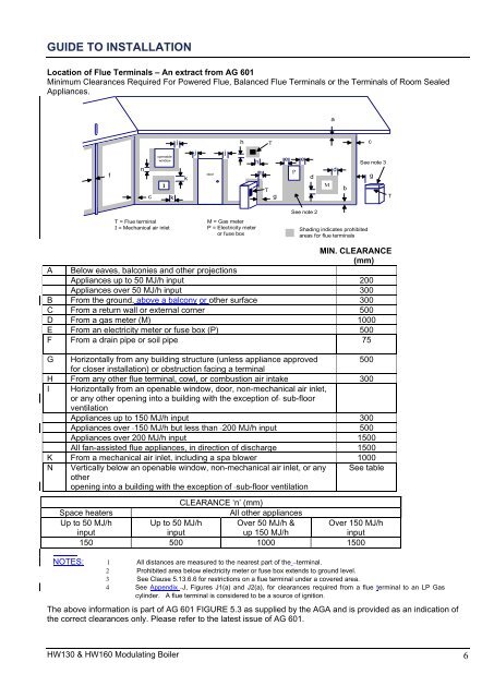
GUIDE TO INSTALLATION<br />
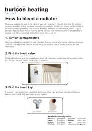
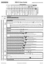
Location of Flue Terminals – An extract from AG 601<br />
Minimum Clearances Required For Powered Flue, Balanced Flue Terminals or the Terminals of Room Sealed<br />
Appliances.<br />
a<br />
f<br />
n<br />
c<br />
openable<br />
window<br />
I<br />
k<br />
j<br />
k<br />
j<br />
door<br />
j<br />
h<br />
T<br />
h<br />
h<br />
T<br />
g<br />
e<br />
P<br />
e<br />
d<br />
M<br />
d<br />
b<br />
c<br />
See note 3<br />
g<br />
T<br />
T = Flue terminal<br />
I = Mechanical air inlet<br />
M = Gas meter<br />
P = Electricity meter<br />
or fuse box<br />
See note 2<br />
Shading indicates prohibited<br />
areas for flue terminals<br />
A<br />
MIN. CLEARANCE<br />
(mm)<br />
Below eaves, balconies and other projections<br />
Appliances up to 50 MJ/h input 200<br />
Appliances over 50 MJ/h input 300<br />
B From the ground, above a balcony or other surface 300<br />
C From a return wall or external corner 500<br />
D From a gas meter (M) 1000<br />
E From an electricity meter or fuse box (P) 500<br />
F From a drain pipe or soil pipe 75<br />
G Horizontally from any building structure (unless appliance approved 500<br />
for closer installation) or obstruction facing a terminal<br />
H From any other flue terminal, cowl, or combustion air intake 300<br />
I Horizontally from an openable window, door, non-mechanical air inlet,<br />
or any other opening into a building with the exception of sub-floor<br />
ventilation<br />
Appliances up to 150 MJ/h input 300<br />
Appliances over 150 MJ/h but less than 200 MJ/h input 500<br />
Appliances over 200 MJ/h input 1500<br />
All fan-assisted flue appliances, in direction of discharge 1500<br />
K From a mechanical air inlet, including a spa blower 1000<br />
N Vertically below an openable window, non-mechanical air inlet, or any<br />
other<br />
opening into a building with the exception of sub-floor ventilation<br />
See table<br />
CLEARANCE „n‟ (mm)<br />
Space heaters<br />
All other appliances<br />
Up to 50 MJ/h<br />
input<br />
Up to 50 MJ/h<br />
input<br />
Over 50 MJ/h &<br />
up 150 MJ/h<br />
Over 150 MJ/h<br />
input<br />
150 500 1000 1500<br />
NOTES: 1 All distances are measured to the nearest part of the terminal.<br />
2 Prohibited area below electricity meter or fuse box extends to ground level.<br />
3 See Clause 5.13.6.6 for restrictions on a flue terminal under a covered area.<br />
4 See Appendix J, Figures J1(a) and J2(a), for clearances required from a flue terminal to an LP Gas<br />
cylinder. A flue terminal is considered to be a source of ignition.<br />
The above information is part of AG 601 FIGURE 5.3 as supplied by the AGA and is provided as an indication of<br />
the correct clearances only. Please refer to the latest issue of AG 601.<br />
<strong>HW130</strong> & <strong>HW160</strong> <strong>Modulating</strong> <strong>Boiler</strong> 6