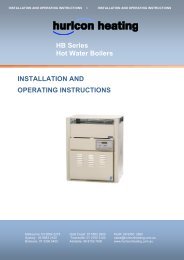
HW130 & HW160 Outdoor Modulating Boiler.pdf - Hurlcon Heating
HW130 & HW160 Outdoor Modulating Boiler.pdf - Hurlcon Heating
HW130 & HW160 Outdoor Modulating Boiler.pdf - Hurlcon Heating

You also want an ePaper? Increase the reach of your titles
YUMPU automatically turns print PDFs into web optimized ePapers that Google loves.
CLEARANCES<br />
The boiler must not be installed against any combustible surface.<br />
Clearances must comply with AS5601 / AG 601.<br />
Clearances from surfaces are:<br />
Front<br />
Both sides<br />
Above<br />
Below<br />
500mm<br />
50mm<br />
300mm<br />
900mm<br />
ELECTRICAL CONNECTION<br />
The boiler is supplied with a standard 10 amp 3 pin plug for connection to a 240V 10 amp earthed GPO. The<br />
boiler incorporates a 240/24 VAC transformer which supplies power to the central heating thermostat only and<br />
must not be used for any additional equipment. All equipment connected to mains power should be protected by<br />
an RCD circuit breaker. The boiler has a 240 volt power supply for the pump, fan and gas valve control. A terminal<br />
strip is provided for connection to the central heating thermostat.<br />
If the supply cord is damaged, it must be replaced by the manufacturer or its service agent or a suitably qualified<br />
person in order to avoid a hazard.<br />
GAS CONNECTION<br />
A ¾”BSP FI is provided for gas line connection. An approved manual shut off valve must be installed in the gas<br />
fitting line before the boiler so that the gas can be turned off and the boiler removed for servicing if required. The<br />
gas shut off valve should be sized the same as the gas fitting line to prevent excessive pressure drop in the gas<br />
pipe.<br />
The gas fitting line should be installed by an authorised person and comply with local regulations and A.G.A. code<br />
AGS5601. The gas line from the meter will usually be of a larger size than the gas inlet connection. Therefore a<br />
reduction to the boiler connection fitting will be necessary. The reduction should be as close to the boiler as<br />
possible.<br />
Before using the boiler, test all connections for gas leaks using soapy water.<br />
The boiler gas valve has a built in pressure regulator with a ⅛” pressure test point provided. On starting the boiler,<br />
a manometer must be used and burner pressure checked against the boiler data plate. The gas valve regulator<br />
may need adjustment to correct manifold pressure. Incorrect burner pressure may void warranty.<br />
<strong>HW130</strong> & <strong>HW160</strong> <strong>Modulating</strong> <strong>Boiler</strong> 7