Avoidance of brake squeal by a separation of the brake ... - tuprints
Avoidance of brake squeal by a separation of the brake ... - tuprints
Avoidance of brake squeal by a separation of the brake ... - tuprints

Create successful ePaper yourself
Turn your PDF publications into a flip-book with our unique Google optimized e-Paper software.
3.3 Free vibrations <strong>of</strong> a rectangular plate with a rectangular or circular hole<br />
a)<br />
b)<br />
y<br />
a<br />
y<br />
l x<br />
y<br />
y m<br />
m l y<br />
b<br />
a<br />
r<br />
b<br />
x m<br />
x<br />
x m<br />
x<br />
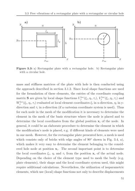
Figure 3.3: a) Rectangular plate with a rectangular hole. b) Rectangular plate<br />
with a circular hole.<br />
mass and stiffness matrices <strong>of</strong> <strong>the</strong> plate with hole is <strong>the</strong>n conducted using<br />
<strong>the</strong> approach described in section 3.1.2. Since local shape functions are used<br />
for <strong>the</strong> formulation <strong>of</strong> <strong>the</strong>se elements, <strong>the</strong> entries <strong>of</strong> <strong>the</strong> coordinate coupling<br />
matrix S are given <strong>by</strong> local shape functions Uj loc (ξ i ,η i ,τ i ), Vj loc (ξ i ,η i ,τ i ) and<br />
Wj loc (ξ i ,η i ,τ i ) evaluated at local element coordinates ξ i in x-direction, η i in y-<br />
direction and τ i in z-direction (if a cartesian coordinate system is used). Thus<br />
for each node in <strong>the</strong> mesh <strong>of</strong> <strong>the</strong> modification it is necessary to determine <strong>the</strong><br />
element in <strong>the</strong> mesh <strong>of</strong> <strong>the</strong> basis structure where <strong>the</strong> node is placed and to<br />
determine <strong>the</strong> local coordinates from <strong>the</strong> global position x i <strong>of</strong> <strong>the</strong> node. In<br />
general, it could be an elaborate procedure to determine <strong>the</strong> element in which<br />
<strong>the</strong> modification’s node is placed, e.g. if different kinds <strong>of</strong> elements were used<br />
in one mesh. However, for <strong>the</strong> rectangular plate presented here, a mesh is used<br />
which consists only <strong>of</strong> bricks with edge angles <strong>of</strong> 90 o shown in Fig. 3.4, a),<br />
which makes it very easy to determine <strong>the</strong> element belonging to <strong>the</strong> considered<br />
hole node at position x i . The second important point is to determine<br />
<strong>the</strong> local coordinates ξ i , η i and τ i from <strong>the</strong> position x i <strong>of</strong> <strong>the</strong> actual node.<br />
Depending on <strong>the</strong> choice <strong>of</strong> <strong>the</strong> element type used to mesh <strong>the</strong> body (e.g.<br />
plate elements), <strong>the</strong>ir shape and <strong>the</strong> local coordinate system used, this might<br />
require additional calculations. Never<strong>the</strong>less, <strong>the</strong> utilization <strong>of</strong> isoparametric<br />
elements, which use (local) shape functions not only to describe displacements<br />
51