Effect of bulk modulus on performance of a hydrostatic transmission ...
Effect of bulk modulus on performance of a hydrostatic transmission ...
Effect of bulk modulus on performance of a hydrostatic transmission ...

You also want an ePaper? Increase the reach of your titles
YUMPU automatically turns print PDFs into web optimized ePapers that Google loves.
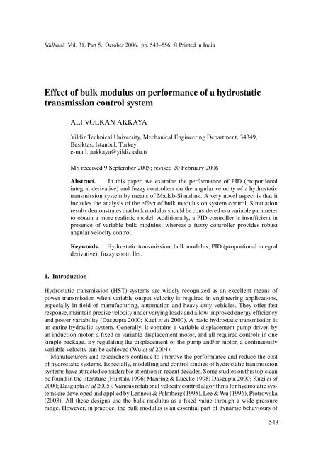
Sādhanā Vol. 31, Part 5, October 2006, pp. 543–556. © Printed in India<br />
<str<strong>on</strong>g>Effect</str<strong>on</strong>g> <str<strong>on</strong>g>of</str<strong>on</strong>g> <str<strong>on</strong>g>bulk</str<strong>on</strong>g> <str<strong>on</strong>g>modulus</str<strong>on</strong>g> <strong>on</strong> <strong>performance</strong> <str<strong>on</strong>g>of</str<strong>on</strong>g> a <strong>hydrostatic</strong><br />
transmissi<strong>on</strong> c<strong>on</strong>trol system<br />
ALI VOLKAN AKKAYA<br />
Yildiz Technical University, Mechanical Engineering Department, 34349,<br />
Besiktas, Istanbul, Turkey<br />
e-mail: aakkaya@yildiz.edu.tr<br />
MS received 9 September 2005; revised 20 February 2006<br />
Abstract. In this paper, we examine the <strong>performance</strong> <str<strong>on</strong>g>of</str<strong>on</strong>g> PID (proporti<strong>on</strong>al<br />
integral derivative) and fuzzy c<strong>on</strong>trollers <strong>on</strong> the angular velocity <str<strong>on</strong>g>of</str<strong>on</strong>g> a <strong>hydrostatic</strong><br />
transmissi<strong>on</strong> system by means <str<strong>on</strong>g>of</str<strong>on</strong>g> Matlab-Simulink. A very novel aspect is that it<br />
includes the analysis <str<strong>on</strong>g>of</str<strong>on</strong>g> the effect <str<strong>on</strong>g>of</str<strong>on</strong>g> <str<strong>on</strong>g>bulk</str<strong>on</strong>g> <str<strong>on</strong>g>modulus</str<strong>on</strong>g> <strong>on</strong> system c<strong>on</strong>trol. Simulati<strong>on</strong><br />
results dem<strong>on</strong>strates that <str<strong>on</strong>g>bulk</str<strong>on</strong>g> <str<strong>on</strong>g>modulus</str<strong>on</strong>g> should be c<strong>on</strong>sidered as a variable parameter<br />
to obtain a more realistic model. Additi<strong>on</strong>ally, a PID c<strong>on</strong>troller is insufficient in<br />
presence <str<strong>on</strong>g>of</str<strong>on</strong>g> variable <str<strong>on</strong>g>bulk</str<strong>on</strong>g> <str<strong>on</strong>g>modulus</str<strong>on</strong>g>, whereas a fuzzy c<strong>on</strong>troller provides robust<br />
angular velocity c<strong>on</strong>trol.<br />
Keywords. Hydrostatic transmissi<strong>on</strong>; <str<strong>on</strong>g>bulk</str<strong>on</strong>g> <str<strong>on</strong>g>modulus</str<strong>on</strong>g>; PID (proporti<strong>on</strong>al integral<br />
derivative); fuzzy c<strong>on</strong>troller.<br />
1. Introducti<strong>on</strong><br />
Hydrostatic transmissi<strong>on</strong> (HST) systems are widely recognized as an excellent means <str<strong>on</strong>g>of</str<strong>on</strong>g><br />
power transmissi<strong>on</strong> when variable output velocity is required in engineering applicati<strong>on</strong>s,<br />
especially in field <str<strong>on</strong>g>of</str<strong>on</strong>g> manufacturing, automati<strong>on</strong> and heavy duty vehicles. They <str<strong>on</strong>g>of</str<strong>on</strong>g>fer fast<br />
resp<strong>on</strong>se, maintain precise velocity under varying loads and allow improved energy efficiency<br />
and power variability (Dasgupta 2000; Kugi et al 2000). A basic <strong>hydrostatic</strong> transmissi<strong>on</strong> is<br />
an entire hydraulic system. Generally, it c<strong>on</strong>tains a variable-displacement pump driven by<br />
an inducti<strong>on</strong> motor, a fixed or variable displacement motor, and all required c<strong>on</strong>trols in <strong>on</strong>e<br />
simple package. By regulating the displacement <str<strong>on</strong>g>of</str<strong>on</strong>g> the pump and/or motor, a c<strong>on</strong>tinuously<br />
variable velocity can be achieved (Wu et al 2004).<br />
Manufacturers and researchers c<strong>on</strong>tinue to improve the <strong>performance</strong> and reduce the cost<br />
<str<strong>on</strong>g>of</str<strong>on</strong>g> <strong>hydrostatic</strong> systems. Especially, modelling and c<strong>on</strong>trol studies <str<strong>on</strong>g>of</str<strong>on</strong>g> <strong>hydrostatic</strong> transmissi<strong>on</strong><br />
systems have attracted c<strong>on</strong>siderable attenti<strong>on</strong> in recent decades. Some studies <strong>on</strong> this topic can<br />
be found in the literature (Huhtala 1996; Manring & Luecke 1998; Dasgupta 2000; Kugi et al<br />
2000; Dasgupta et al 2005). Various rotati<strong>on</strong>al velocity c<strong>on</strong>trol algorithms for <strong>hydrostatic</strong> systems<br />
are developed and applied by Lennevi & Palmberg (1995), Lee & Wu (1996), Piotrowska<br />
(2003). All these designs use the <str<strong>on</strong>g>bulk</str<strong>on</strong>g> <str<strong>on</strong>g>modulus</str<strong>on</strong>g> as a fixed value through a wide pressure<br />
range. However, in practice, the <str<strong>on</strong>g>bulk</str<strong>on</strong>g> <str<strong>on</strong>g>modulus</str<strong>on</strong>g> is an essential part <str<strong>on</strong>g>of</str<strong>on</strong>g> dynamic behaviours <str<strong>on</strong>g>of</str<strong>on</strong>g><br />
543
544 Ali Volkan Akkaya<br />
the hydraulic systems (McCloy & Martin 1980; Watt<strong>on</strong> 1989). Due to temperature variati<strong>on</strong>s<br />
and air entrapment, the <str<strong>on</strong>g>bulk</str<strong>on</strong>g> <str<strong>on</strong>g>modulus</str<strong>on</strong>g> may vary during the operati<strong>on</strong> <str<strong>on</strong>g>of</str<strong>on</strong>g> the hydraulic systems<br />
(Eryilmaz & Wils<strong>on</strong> 2001). A little entrapped air is enough to reduce the <str<strong>on</strong>g>bulk</str<strong>on</strong>g> <str<strong>on</strong>g>modulus</str<strong>on</strong>g><br />
significantly (Merrit 1967; Tan & Sepehri 2002). Moreover, system pressure plays an important<br />
role <strong>on</strong> the <str<strong>on</strong>g>bulk</str<strong>on</strong>g> <str<strong>on</strong>g>modulus</str<strong>on</strong>g> value (Wu et al 2004). Some effects <str<strong>on</strong>g>of</str<strong>on</strong>g> instabilities induced by<br />
<str<strong>on</strong>g>bulk</str<strong>on</strong>g> <str<strong>on</strong>g>modulus</str<strong>on</strong>g> n<strong>on</strong>linearities such as pressure oscillati<strong>on</strong>s in the form <str<strong>on</strong>g>of</str<strong>on</strong>g> pressure waves can<br />
be detrimental to operati<strong>on</strong> <str<strong>on</strong>g>of</str<strong>on</strong>g> hydraulic systems and may result in reduced comp<strong>on</strong>ent life,<br />
loss <str<strong>on</strong>g>of</str<strong>on</strong>g> <strong>performance</strong>, disturbance in c<strong>on</strong>trol systems, reduced efficiency and increased acoustic<br />
noise. In spite <str<strong>on</strong>g>of</str<strong>on</strong>g> these adverse effects, there are few studies about <str<strong>on</strong>g>bulk</str<strong>on</strong>g> <str<strong>on</strong>g>modulus</str<strong>on</strong>g> within<br />
<strong>hydrostatic</strong> transmissi<strong>on</strong> systems. Yu et al (1994) developed an <strong>on</strong>-line parameter identificati<strong>on</strong><br />
method, determining the effective oil <str<strong>on</strong>g>bulk</str<strong>on</strong>g> <str<strong>on</strong>g>modulus</str<strong>on</strong>g> within an actual hydraulic system by<br />
measuring the propagati<strong>on</strong> <str<strong>on</strong>g>of</str<strong>on</strong>g> a pressure wave through a l<strong>on</strong>g pipe. Marning (1997) developed<br />
a linear relati<strong>on</strong> between oil <str<strong>on</strong>g>bulk</str<strong>on</strong>g> <str<strong>on</strong>g>modulus</str<strong>on</strong>g> and pressure for a HST system. However, to<br />
date, nothing has appeared in the literature that addresses the effect <str<strong>on</strong>g>of</str<strong>on</strong>g> <str<strong>on</strong>g>bulk</str<strong>on</strong>g> <str<strong>on</strong>g>modulus</str<strong>on</strong>g> dynamics<br />
incorporated into a <strong>hydrostatic</strong> transmissi<strong>on</strong> model <strong>on</strong> c<strong>on</strong>trol design process <str<strong>on</strong>g>of</str<strong>on</strong>g> the HST<br />
system. In fact, models <str<strong>on</strong>g>of</str<strong>on</strong>g> <strong>hydrostatic</strong> transmissi<strong>on</strong> systems with variable <str<strong>on</strong>g>bulk</str<strong>on</strong>g> <str<strong>on</strong>g>modulus</str<strong>on</strong>g> have<br />
more complex dynamic behaviour than normal. Moreover, having servo c<strong>on</strong>trol <str<strong>on</strong>g>of</str<strong>on</strong>g> the system,<br />
dynamics <str<strong>on</strong>g>of</str<strong>on</strong>g> <str<strong>on</strong>g>bulk</str<strong>on</strong>g> <str<strong>on</strong>g>modulus</str<strong>on</strong>g> becomes more important because the closed-loop system<br />
itself raises the issue <str<strong>on</strong>g>of</str<strong>on</strong>g> stability.<br />
Bulk <str<strong>on</strong>g>modulus</str<strong>on</strong>g> cannot be determined directly and hence needs to be estimated. Based <strong>on</strong><br />
this estimati<strong>on</strong>, corrective acti<strong>on</strong>s may be taken in c<strong>on</strong>trol applicati<strong>on</strong>s for HST systems. The<br />
complex dynamic interacti<strong>on</strong>s between variable <str<strong>on</strong>g>bulk</str<strong>on</strong>g> <str<strong>on</strong>g>modulus</str<strong>on</strong>g> and the c<strong>on</strong>trol acti<strong>on</strong> is investigated<br />
using modelling and simulati<strong>on</strong> analysis. Simulati<strong>on</strong> tests are particularly beneficial<br />
when preparing a model <str<strong>on</strong>g>of</str<strong>on</strong>g> a real system is complicated and time-c<strong>on</strong>suming. A servo <strong>hydrostatic</strong><br />
transmissi<strong>on</strong> c<strong>on</strong>trol system is a good example for this issue. The determinati<strong>on</strong> <str<strong>on</strong>g>of</str<strong>on</strong>g> static<br />
and dynamic behaviours using simulati<strong>on</strong> tests is possible without expensive prototypes. The<br />
simulati<strong>on</strong> also makes a shorter product-designing cycle possible.<br />
This study focuses <strong>on</strong> c<strong>on</strong>trol <strong>performance</strong> <str<strong>on</strong>g>of</str<strong>on</strong>g> a typical HST system. A n<strong>on</strong>linear model<br />
<str<strong>on</strong>g>of</str<strong>on</strong>g> the system is studied by means <str<strong>on</strong>g>of</str<strong>on</strong>g> Matlab-Simulink s<str<strong>on</strong>g>of</str<strong>on</strong>g>tware. The system model is a<br />
combinati<strong>on</strong> <str<strong>on</strong>g>of</str<strong>on</strong>g> each individual comp<strong>on</strong>ent model c<strong>on</strong>sisting <str<strong>on</strong>g>of</str<strong>on</strong>g> pump, valve, hydraulic hose<br />
and hydraulic motor. In additi<strong>on</strong>, the variable <str<strong>on</strong>g>bulk</str<strong>on</strong>g> <str<strong>on</strong>g>modulus</str<strong>on</strong>g> is presented to describe the<br />
effects <str<strong>on</strong>g>of</str<strong>on</strong>g> this phenomen<strong>on</strong> <strong>on</strong> system dynamics and c<strong>on</strong>trol algorithm. For this purpose, two<br />
different hydraulic hose Simulink models are incorporated separately into the system model.<br />
In additi<strong>on</strong>, the models are utilized in the c<strong>on</strong>trol design process. The c<strong>on</strong>trol <str<strong>on</strong>g>of</str<strong>on</strong>g> the angular<br />
velocity <str<strong>on</strong>g>of</str<strong>on</strong>g> the hydraulic motor coupled with load is achieved by PID (proporti<strong>on</strong>al integral<br />
derivative) and fuzzy types <str<strong>on</strong>g>of</str<strong>on</strong>g> c<strong>on</strong>troller. In the first model, <str<strong>on</strong>g>bulk</str<strong>on</strong>g> <str<strong>on</strong>g>modulus</str<strong>on</strong>g> is assumed to have<br />
a fixed value and angular velocity c<strong>on</strong>trol <str<strong>on</strong>g>of</str<strong>on</strong>g> the HST system is carried out with the classical<br />
PID c<strong>on</strong>trol algorithm. In the sec<strong>on</strong>d model, <str<strong>on</strong>g>bulk</str<strong>on</strong>g> <str<strong>on</strong>g>modulus</str<strong>on</strong>g> is defined as a variable parameter<br />
depending <strong>on</strong> entrapped air and system pressure. This new model is applied <strong>on</strong> velocity c<strong>on</strong>trol<br />
<str<strong>on</strong>g>of</str<strong>on</strong>g> the HST system under the same PID c<strong>on</strong>trol parameters. In the following, fuzzy c<strong>on</strong>troller<br />
is implemented in this new model in order to judge its capability against variable <str<strong>on</strong>g>bulk</str<strong>on</strong>g> <str<strong>on</strong>g>modulus</str<strong>on</strong>g><br />
n<strong>on</strong>linearity. The simulati<strong>on</strong> results <str<strong>on</strong>g>of</str<strong>on</strong>g> two c<strong>on</strong>trol approaches are then compared to analyse<br />
the differences in the <strong>performance</strong> <str<strong>on</strong>g>of</str<strong>on</strong>g> the HST system in terms <str<strong>on</strong>g>of</str<strong>on</strong>g> <str<strong>on</strong>g>bulk</str<strong>on</strong>g> <str<strong>on</strong>g>modulus</str<strong>on</strong>g> dynamics.<br />
2. Mathematical model<br />
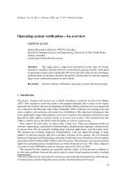
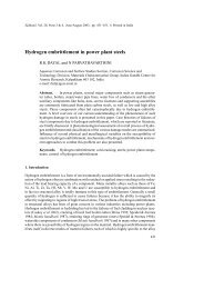
The physical model <str<strong>on</strong>g>of</str<strong>on</strong>g> the HST system c<strong>on</strong>sidered for this study is shown in figure 1. The<br />
variable displacement pump driven by an inducti<strong>on</strong> motor supplies hydraulic power to a fixed
<str<strong>on</strong>g>Effect</str<strong>on</strong>g> <str<strong>on</strong>g>of</str<strong>on</strong>g> <str<strong>on</strong>g>bulk</str<strong>on</strong>g> <str<strong>on</strong>g>modulus</str<strong>on</strong>g> <strong>on</strong> <strong>performance</strong> <str<strong>on</strong>g>of</str<strong>on</strong>g> a transmissi<strong>on</strong> c<strong>on</strong>trol system 545<br />
Figure 1.<br />
Hydrostatic transmissi<strong>on</strong> system.<br />
displacement hydraulic motor for driving load. To protect the system from excessive pressure,<br />
a pressure relief valve is used.<br />
From a research objective point <str<strong>on</strong>g>of</str<strong>on</strong>g> view, the descripti<strong>on</strong>s <str<strong>on</strong>g>of</str<strong>on</strong>g> a system mathematical model<br />
should be as simple as possible. At the same time, it must include important characteristics <str<strong>on</strong>g>of</str<strong>on</strong>g><br />
the real event. One way to understand the system is to separate the system into comp<strong>on</strong>ents<br />
for the purpose <str<strong>on</strong>g>of</str<strong>on</strong>g> modelling. Using a fundamental knowledge <str<strong>on</strong>g>of</str<strong>on</strong>g> physics, for instance the<br />
moment equilibrium and c<strong>on</strong>tinuity equati<strong>on</strong>, a model that represents the dynamics behaviour<br />
<str<strong>on</strong>g>of</str<strong>on</strong>g> each comp<strong>on</strong>ent can be derived at the comp<strong>on</strong>ent levels. Having understood each individual<br />
comp<strong>on</strong>ent, we can understand the overall system by interc<strong>on</strong>necting the comp<strong>on</strong>ents together<br />
to obtain an overall system model (Prasetiawan 2001). In this paper, the model <str<strong>on</strong>g>of</str<strong>on</strong>g> each<br />
comp<strong>on</strong>ent used for the HST system is developed using earlier methods (Jedrzykiewicz et al<br />
1997, 1998).<br />
2.1 Variable-displacement pump<br />
It is assumed that the angular velocity <str<strong>on</strong>g>of</str<strong>on</strong>g> the prime mover (inducti<strong>on</strong> motor) is c<strong>on</strong>stant.<br />
Therefore, angular velocity <str<strong>on</strong>g>of</str<strong>on</strong>g> the pump shaft is c<strong>on</strong>stant. Pump flow rate can be adjusted<br />
with variable displacement via the swashplate displacement angle and can be given as<br />
Q p = αk p η vp , (1)<br />
where, Q p is pump flow rate (m 3 /s), α is displacement angle <str<strong>on</strong>g>of</str<strong>on</strong>g> swashplate ( ◦ ), k p is pump<br />
coefficient (m 3 /s), η vp is pump volumetric efficiency (−) which is assumed not to depend <strong>on</strong><br />
pump rotati<strong>on</strong> angle.<br />
2.2 Pressure relief valve<br />
To simplify, pressure relief valve dynamics is not taken into c<strong>on</strong>siderati<strong>on</strong>. Therefore, two<br />
equati<strong>on</strong> as below are given for passing flow rate through pressure relief valve (m 3 /s) in the<br />
state <str<strong>on</strong>g>of</str<strong>on</strong>g> opening and closing.<br />
Q v = k v (P − P v ), if P>P v , (2)<br />
Q v = 0, if P ≤ P v , (3)
546 Ali Volkan Akkaya<br />
where, k v is slope coefficient <str<strong>on</strong>g>of</str<strong>on</strong>g> valve static characteristic (m 5 /Ns), P is system pressure (Pa)<br />
and P v is valve opening pressure (Pa).<br />
2.3 Hydraulic hose<br />
As in traditi<strong>on</strong>al modelling, the pressurized hose that c<strong>on</strong>nects the pump to the motors is<br />
modelled as volume with a fixed <str<strong>on</strong>g>bulk</str<strong>on</strong>g> <str<strong>on</strong>g>modulus</str<strong>on</strong>g> in this secti<strong>on</strong>. Variable <str<strong>on</strong>g>bulk</str<strong>on</strong>g> <str<strong>on</strong>g>modulus</str<strong>on</strong>g> are<br />
discussed in the following subsecti<strong>on</strong>.<br />
The fluid compressibility relati<strong>on</strong> can be given as in (4). Equati<strong>on</strong> (5) provides the pressure<br />
value from a given flow rate. It is assumed that pressure drop in the hydraulic hose is negligible.<br />
Q c = (V /β)(dP/dt), (4)<br />
(dP/dt) = (β/V )Q c , (5)<br />
where, Q c is flow rate deal with fluid compressibility (m 3 /s), V is the fluid volume (m 3 )<br />
subjected to pressure effect, β is fixed <str<strong>on</strong>g>bulk</str<strong>on</strong>g> <str<strong>on</strong>g>modulus</str<strong>on</strong>g> (Pa).<br />
2.3a Variable <str<strong>on</strong>g>bulk</str<strong>on</strong>g> <str<strong>on</strong>g>modulus</str<strong>on</strong>g> Fluid is an important element <str<strong>on</strong>g>of</str<strong>on</strong>g> <strong>hydrostatic</strong> systems and enables<br />
power transmissi<strong>on</strong>, hence it can influence the dynamic behaviours <str<strong>on</strong>g>of</str<strong>on</strong>g> the system and the<br />
c<strong>on</strong>trol system. The <str<strong>on</strong>g>bulk</str<strong>on</strong>g> <str<strong>on</strong>g>modulus</str<strong>on</strong>g> <str<strong>on</strong>g>of</str<strong>on</strong>g> n<strong>on</strong>-aerated hydraulic oil depends <strong>on</strong> temperature and<br />
pressure, for mineral oils with additives its value ranges from 1200 to 2000 MPa. Moreover,<br />
system pressure and entrapped air affect the <str<strong>on</strong>g>bulk</str<strong>on</strong>g> <str<strong>on</strong>g>modulus</str<strong>on</strong>g> value. If a hydraulic hose is used<br />
rather than a steel pipe, the <str<strong>on</strong>g>bulk</str<strong>on</strong>g> <str<strong>on</strong>g>modulus</str<strong>on</strong>g> <str<strong>on</strong>g>of</str<strong>on</strong>g> this secti<strong>on</strong> may be c<strong>on</strong>siderably reduced. Owing<br />
to these reas<strong>on</strong>s, the parameters influencing <str<strong>on</strong>g>bulk</str<strong>on</strong>g> <str<strong>on</strong>g>modulus</str<strong>on</strong>g> value must be included in the HST<br />
model for more accurate system dynamics.<br />
The equati<strong>on</strong> which gives the variable <str<strong>on</strong>g>bulk</str<strong>on</strong>g> <str<strong>on</strong>g>modulus</str<strong>on</strong>g> <str<strong>on</strong>g>of</str<strong>on</strong>g> fluid-air mixture in a flexible<br />
c<strong>on</strong>tainer is as follows (McCloy & Martin 1980):<br />
1<br />
= 1 + 1 + V a 1<br />
· , (6)<br />
β v β f β h V t β a<br />
where, the subcripts a, f and h refer to air, fluid, and hose respectively. It is assumed that the<br />
initial total volume V t = V f + V a , and that β f ≫ β a . Thus <str<strong>on</strong>g>bulk</str<strong>on</strong>g> <str<strong>on</strong>g>modulus</str<strong>on</strong>g> will be less than any<br />
β f , β h ,orV t /V a β a . The <str<strong>on</strong>g>bulk</str<strong>on</strong>g> <str<strong>on</strong>g>modulus</str<strong>on</strong>g> <str<strong>on</strong>g>of</str<strong>on</strong>g> the fluid β f is obtained from the manufacturers<br />
data. The adiabatic <str<strong>on</strong>g>bulk</str<strong>on</strong>g> <str<strong>on</strong>g>modulus</str<strong>on</strong>g> used for air is (C p /C v )P = 1·4P . With these assumpti<strong>on</strong>s,<br />
(6) can be rewritten as in,<br />
1<br />
= 1 + 1 +<br />
s<br />
β v β f β h 1·4 · P , (7)<br />
where, s is entrapped air percent in the total volume (s = V a /V t ).<br />
2.4 Hydraulic motor and load<br />
Flow rate used in the hydraulic motor (m 3 /s) can be written as in<br />
Q m = k m ω/η vm , (8)<br />
where, k m is hydraulic motor coefficient (m 3 ), ω is angular velocity <str<strong>on</strong>g>of</str<strong>on</strong>g> hydraulic motor (1/s)<br />
and η vm is volumetric efficiency <str<strong>on</strong>g>of</str<strong>on</strong>g> the motor (−). It is assumed that hydraulic motor efficiency<br />
does not depend <strong>on</strong> its shaft rotati<strong>on</strong> angle. Hydraulic motor torque (Nm) can be written as,<br />
M m = k mt P η mm , (9)
<str<strong>on</strong>g>Effect</str<strong>on</strong>g> <str<strong>on</strong>g>of</str<strong>on</strong>g> <str<strong>on</strong>g>bulk</str<strong>on</strong>g> <str<strong>on</strong>g>modulus</str<strong>on</strong>g> <strong>on</strong> <strong>performance</strong> <str<strong>on</strong>g>of</str<strong>on</strong>g> a transmissi<strong>on</strong> c<strong>on</strong>trol system 547<br />
where, k mt is motor torque coefficient (m 3 ), P is pressure drop in hydraulic motor (Pa)<br />
and η mm is mechanical efficiency <str<strong>on</strong>g>of</str<strong>on</strong>g> hydraulic the motor (−). The torque produced in the<br />
hydraulic motor (Nm) is equal to the sum <str<strong>on</strong>g>of</str<strong>on</strong>g> the moments from the motor loads and can be<br />
given as,<br />
M m = M I + M B + M o , (10)<br />
where, M I , M B and M o are the moments resulting from load inertia, fricti<strong>on</strong> force and machine<br />
operati<strong>on</strong> respectively. These moments can be denoted as<br />
M m = I m (dω/dt) + Bω + M o , (11)<br />
where, I m is the inertia <str<strong>on</strong>g>of</str<strong>on</strong>g> the hydraulic motor shaft (Nms 2 ), B is viscous fricti<strong>on</strong> coefficient<br />
<str<strong>on</strong>g>of</str<strong>on</strong>g> motor and its shaft (Ns/m), and ω is angular velocity <str<strong>on</strong>g>of</str<strong>on</strong>g> motor shaft (1/s). Equati<strong>on</strong> (11)<br />
can be used to determine the angular velocity <str<strong>on</strong>g>of</str<strong>on</strong>g> the hydraulic motor shaft. This equati<strong>on</strong> is<br />
rearranged for angular velocity as<br />
dω/dt = (M m − Bω − M o )/I m . (12)<br />
2.5 Hydrostatic transmissi<strong>on</strong> system<br />
The fundamental mathematical models <str<strong>on</strong>g>of</str<strong>on</strong>g> the system comp<strong>on</strong>ents and phenomena occurring<br />
in <strong>hydrostatic</strong> systems are c<strong>on</strong>veniently combined to obtain the overall HST system model.<br />
Accordingly, a <strong>hydrostatic</strong> transmissi<strong>on</strong> is modelled as a lumped system. In the development<br />
<str<strong>on</strong>g>of</str<strong>on</strong>g> the dynamic model <str<strong>on</strong>g>of</str<strong>on</strong>g> the system, it is assumed that static and dynamic features <str<strong>on</strong>g>of</str<strong>on</strong>g> the<br />
transmissi<strong>on</strong> do not depend up<strong>on</strong> the directi<strong>on</strong> <str<strong>on</strong>g>of</str<strong>on</strong>g> hydraulic motor rotati<strong>on</strong> and the transmissi<strong>on</strong><br />
is a state <str<strong>on</strong>g>of</str<strong>on</strong>g> thermal balance. Leakage flows in pump and motor are not taken into account<br />
during the modelling.<br />
The mathematical model <str<strong>on</strong>g>of</str<strong>on</strong>g> the HST system c<strong>on</strong>sists <str<strong>on</strong>g>of</str<strong>on</strong>g> two equati<strong>on</strong>s as below:<br />
equality <str<strong>on</strong>g>of</str<strong>on</strong>g> flow rate:<br />
moment:<br />
Q p = Q m + Q c + Q v , (13)<br />
M m = M I + M B + M o . (14)<br />
Using (5) and (12), the following are then obtained,<br />
dP/dt = (β/V )(Q p − Q m − Q v ), (15)<br />
dω/dt = (M m − Bω − M o )/I m . (16)<br />
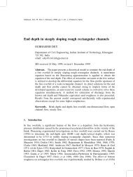
A comm<strong>on</strong>ly available general purpose simulati<strong>on</strong> package Matlab/Simulink is used to<br />
solve the n<strong>on</strong>linear equati<strong>on</strong>s. The Simulink model based <strong>on</strong> the comp<strong>on</strong>ent mathematical<br />
models <str<strong>on</strong>g>of</str<strong>on</strong>g> HST system is given in figure 2. The comp<strong>on</strong>ent models can be easily modified<br />
in accordance width specific c<strong>on</strong>structi<strong>on</strong>s. Accordingly, when <str<strong>on</strong>g>bulk</str<strong>on</strong>g> <str<strong>on</strong>g>modulus</str<strong>on</strong>g> is rebuilt in the<br />
hydraulic hose comp<strong>on</strong>ent with regard to (7), the sec<strong>on</strong>d model can be generated.
548 Ali Volkan Akkaya<br />
Figure 2.<br />
Simulink model <str<strong>on</strong>g>of</str<strong>on</strong>g> <strong>hydrostatic</strong> transmissi<strong>on</strong> system.<br />
3. C<strong>on</strong>trol applicati<strong>on</strong>s<br />
Most publicati<strong>on</strong>s related to the HST c<strong>on</strong>trol are related to the speed c<strong>on</strong>trol <str<strong>on</strong>g>of</str<strong>on</strong>g> the hydraulic<br />
motor c<strong>on</strong>nected to the load. In order to achieve this goal, different closed-loop c<strong>on</strong>trol design<br />
strategies can be used. However, Lee & Wu (1996) showed that using <strong>on</strong>ly pump displacement<br />
to regulate load speed is the most effective <str<strong>on</strong>g>of</str<strong>on</strong>g> all the methods they tested. In additi<strong>on</strong>, Re et al<br />
(1996) c<strong>on</strong>cluded that the sole use <str<strong>on</strong>g>of</str<strong>on</strong>g> pump displacement actuati<strong>on</strong> to c<strong>on</strong>trol <strong>on</strong>e load speed<br />
<str<strong>on</strong>g>of</str<strong>on</strong>g> a system with variable-displacement pump and motor is the most efficient, and should be<br />
always preferred whenever possible. For this reas<strong>on</strong>, in the HST systems being c<strong>on</strong>sidered in<br />
this study, the output angular velocity is c<strong>on</strong>trolled by the flow rate supplied to the hydraulic<br />
motor, and this flowrate is adjusted by the swashplate angle <str<strong>on</strong>g>of</str<strong>on</strong>g> the variable-displacement<br />
pump. Swashplate dynamics are not taken into c<strong>on</strong>siderati<strong>on</strong> in the c<strong>on</strong>trol applicati<strong>on</strong> in<br />
this study for the sake <str<strong>on</strong>g>of</str<strong>on</strong>g> simplicity. In additi<strong>on</strong>, the swashplate c<strong>on</strong>trol system usually has<br />
faster dynamics than the rest <str<strong>on</strong>g>of</str<strong>on</strong>g> the system, and therefore neglecting its dynamics is justified<br />
(Watt<strong>on</strong> 1989).<br />
To precisely c<strong>on</strong>trol the angular velocity <str<strong>on</strong>g>of</str<strong>on</strong>g> the hydraulic motor in <strong>hydrostatic</strong> transmissi<strong>on</strong><br />
c<strong>on</strong>trol systems, an appropriate c<strong>on</strong>troller must be designed in advance. In industrial applicati<strong>on</strong>s,<br />
classical c<strong>on</strong>trol methods such as PI, PID are being used for velocity c<strong>on</strong>trol <str<strong>on</strong>g>of</str<strong>on</strong>g> HST<br />
systems. It is crucial to determine c<strong>on</strong>troller parameters accurately because PID c<strong>on</strong>trol methods<br />
have linear characteristics. They are sometimes insufficient to overcome n<strong>on</strong>linearities<br />
which exist in the nature <str<strong>on</strong>g>of</str<strong>on</strong>g> the HST systems for high precisi<strong>on</strong> applicati<strong>on</strong>s (Tikkanen et al<br />
1995; Prasetiawan 2001). In particular, the <str<strong>on</strong>g>bulk</str<strong>on</strong>g> <str<strong>on</strong>g>modulus</str<strong>on</strong>g> ought to be regarded as a source <str<strong>on</strong>g>of</str<strong>on</strong>g><br />
significant n<strong>on</strong>linearity for this type <str<strong>on</strong>g>of</str<strong>on</strong>g> c<strong>on</strong>troller. Thus, the c<strong>on</strong>troller has to be very robust<br />
to account for such wide variati<strong>on</strong>. Use <str<strong>on</strong>g>of</str<strong>on</strong>g> knowledge-based systems in process c<strong>on</strong>trol is<br />
increasing, especially in the fields <str<strong>on</strong>g>of</str<strong>on</strong>g> fuzzy c<strong>on</strong>trol (Tanaka 1996). Unlike classical c<strong>on</strong>trol<br />
methods, the fuzzy c<strong>on</strong>troller is designed with linguistic terms to cope with the n<strong>on</strong>linearities.<br />
Therefore, this c<strong>on</strong>trol method is also applied to judge its capacity to reduce the adverse<br />
effect <str<strong>on</strong>g>of</str<strong>on</strong>g> variable <str<strong>on</strong>g>bulk</str<strong>on</strong>g> <str<strong>on</strong>g>modulus</str<strong>on</strong>g>.<br />
3.1 PID c<strong>on</strong>trol<br />
The structure <str<strong>on</strong>g>of</str<strong>on</strong>g> the PID c<strong>on</strong>trol algorithm used for the angular velocity c<strong>on</strong>trol <str<strong>on</strong>g>of</str<strong>on</strong>g> HST<br />
system is given in (17) and (18) below. Ziegler-Nichols method is implemented for tuning<br />
c<strong>on</strong>trol parameters, such as proporti<strong>on</strong>al gain (K p ), derivative time c<strong>on</strong>stant (τ d ) and integral<br />
time c<strong>on</strong>stant (τ i ) (Ogata 1990). After fine adjustments, the optimal c<strong>on</strong>trol parameters are
<str<strong>on</strong>g>Effect</str<strong>on</strong>g> <str<strong>on</strong>g>of</str<strong>on</strong>g> <str<strong>on</strong>g>bulk</str<strong>on</strong>g> <str<strong>on</strong>g>modulus</str<strong>on</strong>g> <strong>on</strong> <strong>performance</strong> <str<strong>on</strong>g>of</str<strong>on</strong>g> a transmissi<strong>on</strong> c<strong>on</strong>trol system 549<br />
Figure 3.<br />
Simulink model <str<strong>on</strong>g>of</str<strong>on</strong>g> HST system for PID c<strong>on</strong>trol.<br />
determined for the reference angular velocity. Figure 3 shows the Simulink model <str<strong>on</strong>g>of</str<strong>on</strong>g> the<br />
PID-c<strong>on</strong>trolled HST system.<br />
uv(t) = K p · e(t) + K p · τ d · de(t) + K ∫<br />
p<br />
dt τ i<br />
e(t) · dt, (17)<br />
e(t) = ω r − ω. (18)<br />
3.2 Fuzzy c<strong>on</strong>trol<br />
Fuzzy logic has come a l<strong>on</strong>g way since it was first presented to technical society, when<br />
Zadeh (1965) first published his seminal work. Since then, the subject has been the focus<br />
<str<strong>on</strong>g>of</str<strong>on</strong>g> many independent research investigati<strong>on</strong>s. The attenti<strong>on</strong> currently being paid to fuzzy<br />
logic is most likely the result <str<strong>on</strong>g>of</str<strong>on</strong>g> present popular c<strong>on</strong>sumer products employing fuzzy logic.<br />
The advantages <str<strong>on</strong>g>of</str<strong>on</strong>g> this method are its applicability to n<strong>on</strong>linear systems, simplicity, good<br />
<strong>performance</strong> and robust character. These days, this method is being applied to engineering<br />
c<strong>on</strong>trol systems such as robot c<strong>on</strong>trol, flight c<strong>on</strong>trol, motor c<strong>on</strong>trol and power systems<br />
successfully.<br />
In fuzzy c<strong>on</strong>trol, linguistic descripti<strong>on</strong>s <str<strong>on</strong>g>of</str<strong>on</strong>g> human expertise in c<strong>on</strong>trolling a process are<br />
represented as fuzzy rules or relati<strong>on</strong>s. This knowledge base is used by an inference mechanism,<br />
in c<strong>on</strong>juncti<strong>on</strong> with some knowledge <str<strong>on</strong>g>of</str<strong>on</strong>g> the states <str<strong>on</strong>g>of</str<strong>on</strong>g> the process in order to determine<br />
c<strong>on</strong>trol acti<strong>on</strong>s. Unlike the c<strong>on</strong>venti<strong>on</strong>al c<strong>on</strong>troller, there are three procedures involved in the<br />
implementati<strong>on</strong> <str<strong>on</strong>g>of</str<strong>on</strong>g> a fuzzy c<strong>on</strong>troller: fuzzificati<strong>on</strong> <str<strong>on</strong>g>of</str<strong>on</strong>g> inputs, and fuzzy inference based <strong>on</strong><br />
the knowledge and the defuzzificati<strong>on</strong> <str<strong>on</strong>g>of</str<strong>on</strong>g> the rule-based c<strong>on</strong>trol signal. The structure <str<strong>on</strong>g>of</str<strong>on</strong>g> the<br />
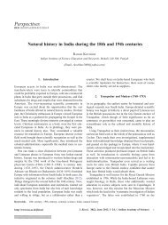
fuzzy c<strong>on</strong>troller is seen in figure 4.<br />
An applied fuzzy c<strong>on</strong>troller needs two input signals. These signals are error (e) and derivative<br />
<str<strong>on</strong>g>of</str<strong>on</strong>g> error (de) respectively. The usual overlapped triangular fuzzy membership functi<strong>on</strong>s<br />
are used for two input signals (e, de/dt) and the output signal (u). Figure 5 shows the structure<br />
<str<strong>on</strong>g>of</str<strong>on</strong>g> the membership functi<strong>on</strong>s <str<strong>on</strong>g>of</str<strong>on</strong>g> input and output signals. Input signals are transformed<br />
at intervals <str<strong>on</strong>g>of</str<strong>on</strong>g> [−1, 1] by scaling factors which are Ge and Gde.<br />
In the fuzzificati<strong>on</strong> process, all input signals are expressed as linguistic values which are:<br />
NB – negative big, NM – negative medium, NS-negative small, ZE-zero, PS-positive small,<br />
PM-positive medium, PB-positive big. After input signals are c<strong>on</strong>verted to fuzzy linguistic<br />
variables, these variables are sent to the inference mechanism to create output signals.
550 Ali Volkan Akkaya<br />
Figure 4.<br />
Structure <str<strong>on</strong>g>of</str<strong>on</strong>g> a fuzzy c<strong>on</strong>troller.<br />
The inference process c<strong>on</strong>sists <str<strong>on</strong>g>of</str<strong>on</strong>g> forty nine rules driven by the linguistic values <str<strong>on</strong>g>of</str<strong>on</strong>g> the input<br />
signals. These fuzzy rules written as a rule base are shown given in table 1. The rule base is<br />
developed by heuristics with error in motor angular velocity and derivati<strong>on</strong> <str<strong>on</strong>g>of</str<strong>on</strong>g> error in this<br />
velocity. For instance, <strong>on</strong>e <str<strong>on</strong>g>of</str<strong>on</strong>g> the possible rules is: IF e = PS and de = NB THAN u = NM.<br />
This rule can be explained as in the following: If the error is small, angular velocity <str<strong>on</strong>g>of</str<strong>on</strong>g> hydraulic<br />
motor is around the reference velocity. Significantly big negative value <str<strong>on</strong>g>of</str<strong>on</strong>g> derivati<strong>on</strong> <str<strong>on</strong>g>of</str<strong>on</strong>g> error<br />
shows that the motor velocity is rapidly approaching the reference positi<strong>on</strong>. C<strong>on</strong>sequently,<br />
c<strong>on</strong>troller output should be negative middle to prevent overshoot and to create a brake effect.<br />
As a rule-inference method, the Mamdani Method is selected because <str<strong>on</strong>g>of</str<strong>on</strong>g> its general acceptance<br />
(Tanaka 1996).<br />
Defuzzificati<strong>on</strong> transforms the c<strong>on</strong>trol linguistic variables into the exact c<strong>on</strong>trol output. In<br />
defuzzificati<strong>on</strong>, the method <str<strong>on</strong>g>of</str<strong>on</strong>g> centre <str<strong>on</strong>g>of</str<strong>on</strong>g> gravity is implemented (Tanaka 1996), as<br />
u =<br />
n∑ n∑<br />
W i B i / W i (19)<br />
i=1 i=1<br />
Figure 5. Triangular fuzzy membership<br />
functi<strong>on</strong>s, (a) e input signal, (b) de<br />
input signal, (c) u output signals.
<str<strong>on</strong>g>Effect</str<strong>on</strong>g> <str<strong>on</strong>g>of</str<strong>on</strong>g> <str<strong>on</strong>g>bulk</str<strong>on</strong>g> <str<strong>on</strong>g>modulus</str<strong>on</strong>g> <strong>on</strong> <strong>performance</strong> <str<strong>on</strong>g>of</str<strong>on</strong>g> a transmissi<strong>on</strong> c<strong>on</strong>trol system 551<br />
Table 1. Rule base for fuzzy c<strong>on</strong>trol.<br />
de\e NB NM NS ZE PS PM PB<br />
NB NB NB NB NM NM NS ZE<br />
NM NB NB NM NS NS ZE PS<br />
NS NB NM NS NS ZE PS PM<br />
ZE NM NS NS ZE PS PS PM<br />
PS NM NS ZE PS PS PM PB<br />
PM NS ZE PS PS PM PB PB<br />
PB ZE PS PM PM PB PB PB<br />
where, u is the output signal <str<strong>on</strong>g>of</str<strong>on</strong>g> the fuzzy c<strong>on</strong>troller, W i is the degree <str<strong>on</strong>g>of</str<strong>on</strong>g> the firing <str<strong>on</strong>g>of</str<strong>on</strong>g> the ith<br />
rule, B i is the centroid <str<strong>on</strong>g>of</str<strong>on</strong>g> the c<strong>on</strong>sequent fuzzy subset <str<strong>on</strong>g>of</str<strong>on</strong>g> ith rule. Real values <str<strong>on</strong>g>of</str<strong>on</strong>g> c<strong>on</strong>trol output<br />
signal (uv) are determined by the scaling factor <str<strong>on</strong>g>of</str<strong>on</strong>g> Guv. As a result, the fuzzy c<strong>on</strong>troller<br />
built-in Fuzzy Logic Toolbox <str<strong>on</strong>g>of</str<strong>on</strong>g> the Matlab program has been added to the Simulink model<br />
<str<strong>on</strong>g>of</str<strong>on</strong>g> <strong>hydrostatic</strong> transmissi<strong>on</strong> system for simulati<strong>on</strong> analysis (figure 6).<br />
4. Simulati<strong>on</strong> results and discussi<strong>on</strong><br />
The validity <str<strong>on</strong>g>of</str<strong>on</strong>g> the influence <str<strong>on</strong>g>of</str<strong>on</strong>g> <str<strong>on</strong>g>bulk</str<strong>on</strong>g> <str<strong>on</strong>g>modulus</str<strong>on</strong>g> dynamics <strong>on</strong> HST c<strong>on</strong>trol system has been<br />
tested in computer simulati<strong>on</strong>s. In order to carry out simulati<strong>on</strong>, some physical and simulati<strong>on</strong><br />
parameters corresp<strong>on</strong>ding to HST system are taken from work <str<strong>on</strong>g>of</str<strong>on</strong>g> McCloy & Martin (1980)<br />
and Jedrzykiewicz et al (1997, 1998), and other c<strong>on</strong>trol parameters are as given in table 2.<br />
Open loop pressure and angular velocity resp<strong>on</strong>ses <str<strong>on</strong>g>of</str<strong>on</strong>g> the HST system are given in figures 7a<br />
and b respectively, under fixed <str<strong>on</strong>g>bulk</str<strong>on</strong>g> <str<strong>on</strong>g>modulus</str<strong>on</strong>g> and variable <str<strong>on</strong>g>bulk</str<strong>on</strong>g> <str<strong>on</strong>g>modulus</str<strong>on</strong>g>. Comparing the simulati<strong>on</strong><br />
results shows that the model including variable <str<strong>on</strong>g>bulk</str<strong>on</strong>g> <str<strong>on</strong>g>modulus</str<strong>on</strong>g> shows flexible dynamics<br />
and decreasing system stiffness (figure 7a). Moreover, a degree <str<strong>on</strong>g>of</str<strong>on</strong>g> aerati<strong>on</strong> less than 1%<br />
brings about c<strong>on</strong>siderable changes <str<strong>on</strong>g>of</str<strong>on</strong>g> velocity and pressure resp<strong>on</strong>ses because the aerati<strong>on</strong> <str<strong>on</strong>g>of</str<strong>on</strong>g><br />
the working fluid results in decrease <str<strong>on</strong>g>of</str<strong>on</strong>g> fluid <str<strong>on</strong>g>bulk</str<strong>on</strong>g> <str<strong>on</strong>g>modulus</str<strong>on</strong>g> and changes its characteristics as<br />
a functi<strong>on</strong> <str<strong>on</strong>g>of</str<strong>on</strong>g> pressure.<br />
The dynamic behaviour patterns in figure 8 are obtained from PID c<strong>on</strong>trol. It is observed<br />
from figure 8a that the system model including the fixed <str<strong>on</strong>g>bulk</str<strong>on</strong>g> <str<strong>on</strong>g>modulus</str<strong>on</strong>g> is in good agreement<br />
with reference velocity. In c<strong>on</strong>trast to this, the simulati<strong>on</strong> result <str<strong>on</strong>g>of</str<strong>on</strong>g> the model with variable<br />
<str<strong>on</strong>g>bulk</str<strong>on</strong>g> <str<strong>on</strong>g>modulus</str<strong>on</strong>g> show oscillati<strong>on</strong>s in the transient regime. The reas<strong>on</strong> is that the <str<strong>on</strong>g>bulk</str<strong>on</strong>g> <str<strong>on</strong>g>modulus</str<strong>on</strong>g><br />
Figure 6.<br />
Simulink model <str<strong>on</strong>g>of</str<strong>on</strong>g> HST system for fuzzy c<strong>on</strong>troller.
552 Ali Volkan Akkaya<br />
Table 2. Physical and simulati<strong>on</strong> parameters.<br />
Moments resulting from machine operati<strong>on</strong> M o (Nm) 150<br />
Viscous fricti<strong>on</strong> coefficient B (Ns/m) 15<br />
Displacement angle <str<strong>on</strong>g>of</str<strong>on</strong>g> swashplate a ( ◦ ) 16 for open-loop<br />
Inertia <str<strong>on</strong>g>of</str<strong>on</strong>g> hydraulic motor shaft I m (Nms 2 ) 0·04<br />
Opening pressure value <str<strong>on</strong>g>of</str<strong>on</strong>g> valve P v (Pa) 12 × 10 6<br />
Fluid volume subjected to pressure effect V (m 3 ) 1·4145 × 10 −4<br />
Pump coefficient k p (m 3 / ◦ s) 2·688 × 10 −5<br />
Hydraulic motor coefficient k m (m 3 ) 3·979 × 10 −5<br />
Motor torque coefficient k mt (m 3 ) 3·979 × 10 −5<br />
Slope coefficient <str<strong>on</strong>g>of</str<strong>on</strong>g> relief valve k v (m 5 /Ns) 0·2 × 10 −9<br />
Pump volumetric efficiency η vp (%) 97<br />
Mechanical efficiency <str<strong>on</strong>g>of</str<strong>on</strong>g> hydraulic motor η mm (%) 95<br />
Bulk <str<strong>on</strong>g>modulus</str<strong>on</strong>g> <str<strong>on</strong>g>of</str<strong>on</strong>g> fluid β f (Pa) 1·49 × 10 9<br />
Bulk <str<strong>on</strong>g>modulus</str<strong>on</strong>g> <str<strong>on</strong>g>of</str<strong>on</strong>g> hose β h (Pa) 47 × 10 7<br />
Degree <str<strong>on</strong>g>of</str<strong>on</strong>g> entrapped air s (%) 0·5<br />
Reference angular velocity ω r (1/s) 7<br />
Proporti<strong>on</strong>al gain c<strong>on</strong>stant K p (–) 70<br />
Derivative time c<strong>on</strong>stant τ d (–) 0·0002875<br />
Integral time c<strong>on</strong>stant τ i (–) 0·00115<br />
Scaling factor <str<strong>on</strong>g>of</str<strong>on</strong>g> error Ge (–) 0·1<br />
Scaling factor <str<strong>on</strong>g>of</str<strong>on</strong>g> derivative <str<strong>on</strong>g>of</str<strong>on</strong>g> error Gde (–) 0·0001<br />
Scaling factor <str<strong>on</strong>g>of</str<strong>on</strong>g> c<strong>on</strong>trol signal Gu (–) 1500<br />
Figure 7.<br />
velocity.<br />
Open loop resp<strong>on</strong>ses <str<strong>on</strong>g>of</str<strong>on</strong>g> HST system under fixed and variable (a) system pressure, (b) angular
<str<strong>on</strong>g>Effect</str<strong>on</strong>g> <str<strong>on</strong>g>of</str<strong>on</strong>g> <str<strong>on</strong>g>bulk</str<strong>on</strong>g> <str<strong>on</strong>g>modulus</str<strong>on</strong>g> <strong>on</strong> <strong>performance</strong> <str<strong>on</strong>g>of</str<strong>on</strong>g> a transmissi<strong>on</strong> c<strong>on</strong>trol system 553<br />
Figure 8. PID c<strong>on</strong>trol resp<strong>on</strong>ses <str<strong>on</strong>g>of</str<strong>on</strong>g> HST system for fixed and variable <str<strong>on</strong>g>bulk</str<strong>on</strong>g> <str<strong>on</strong>g>modulus</str<strong>on</strong>g> (a) angular<br />
velocity, (b) system pressure, (c) variable <str<strong>on</strong>g>bulk</str<strong>on</strong>g> <str<strong>on</strong>g>modulus</str<strong>on</strong>g>.<br />
value becomes lower than that <str<strong>on</strong>g>of</str<strong>on</strong>g> the fixed <strong>on</strong>e (figure 8b) and changes with system pressure<br />
(figure 8c). The same characteristic is seen for increasing load moment at 0·03 s. The above<br />
results indicate that with change in the <str<strong>on</strong>g>bulk</str<strong>on</strong>g> <str<strong>on</strong>g>modulus</str<strong>on</strong>g>, peak pressure as well as fluctuati<strong>on</strong> <str<strong>on</strong>g>of</str<strong>on</strong>g><br />
the fluid pressure increase in closed loop c<strong>on</strong>trol applicati<strong>on</strong>s. This increases the settling time<br />
<str<strong>on</strong>g>of</str<strong>on</strong>g> the system’s resp<strong>on</strong>ses. This may cause to failure <str<strong>on</strong>g>of</str<strong>on</strong>g> the stability <str<strong>on</strong>g>of</str<strong>on</strong>g> the system. Therefore,<br />
it is necessary to revise the c<strong>on</strong>trol parameters or apply a more robust c<strong>on</strong>troller in terms <str<strong>on</strong>g>of</str<strong>on</strong>g><br />
variable <str<strong>on</strong>g>bulk</str<strong>on</strong>g> <str<strong>on</strong>g>modulus</str<strong>on</strong>g>.<br />
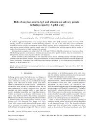
Fuzzy and PID c<strong>on</strong>trol resp<strong>on</strong>ses <str<strong>on</strong>g>of</str<strong>on</strong>g> HST system under the variable <str<strong>on</strong>g>bulk</str<strong>on</strong>g> <str<strong>on</strong>g>modulus</str<strong>on</strong>g> are<br />
depicted in figure 9. Simulati<strong>on</strong> results <str<strong>on</strong>g>of</str<strong>on</strong>g> fuzzy c<strong>on</strong>troller show good <strong>performance</strong> compared<br />
with PID c<strong>on</strong>troller in tracking referenced velocity (figure 9a). In additi<strong>on</strong>, fuzzy c<strong>on</strong>troller<br />
rejects the effect <str<strong>on</strong>g>of</str<strong>on</strong>g> loading <strong>on</strong> pressure dynamics (figure 9b). Figure 9c indicates that fuzzy<br />
c<strong>on</strong>troller minimizes the fluctuati<strong>on</strong>s <str<strong>on</strong>g>of</str<strong>on</strong>g> <str<strong>on</strong>g>bulk</str<strong>on</strong>g> <str<strong>on</strong>g>modulus</str<strong>on</strong>g> value. This is the reas<strong>on</strong> why the<br />
fuzzy resp<strong>on</strong>se is more robust. Figure 9d shows that PID c<strong>on</strong>troller can work safely up to<br />
200 Hz, whereas a fuzzy c<strong>on</strong>troller is capable <str<strong>on</strong>g>of</str<strong>on</strong>g> enduring 400 Hz. Therefore, a fuzzy c<strong>on</strong>troller
554 Ali Volkan Akkaya<br />
Figure 9. Fuzzy and PID c<strong>on</strong>trol resp<strong>on</strong>ses <str<strong>on</strong>g>of</str<strong>on</strong>g> HST system under variable <str<strong>on</strong>g>bulk</str<strong>on</strong>g> <str<strong>on</strong>g>modulus</str<strong>on</strong>g>. (a) Angular<br />
velocity, (b) system pressure, (c) variable <str<strong>on</strong>g>bulk</str<strong>on</strong>g> <str<strong>on</strong>g>modulus</str<strong>on</strong>g>, (d) velocity bode diagram.<br />
increases the stability c<strong>on</strong>diti<strong>on</strong>s <str<strong>on</strong>g>of</str<strong>on</strong>g> a hydraulic transmissi<strong>on</strong> system in presence <str<strong>on</strong>g>of</str<strong>on</strong>g> variable<br />
<str<strong>on</strong>g>bulk</str<strong>on</strong>g> n<strong>on</strong>linearity.<br />
5. C<strong>on</strong>clusi<strong>on</strong><br />
The effects <str<strong>on</strong>g>of</str<strong>on</strong>g> <str<strong>on</strong>g>bulk</str<strong>on</strong>g> <str<strong>on</strong>g>modulus</str<strong>on</strong>g> n<strong>on</strong>linearity <strong>on</strong> the <strong>performance</strong> <str<strong>on</strong>g>of</str<strong>on</strong>g> a <strong>hydrostatic</strong> transmissi<strong>on</strong><br />
c<strong>on</strong>trol system have been analysed through system modelling and simulati<strong>on</strong>. This study has
<str<strong>on</strong>g>Effect</str<strong>on</strong>g> <str<strong>on</strong>g>of</str<strong>on</strong>g> <str<strong>on</strong>g>bulk</str<strong>on</strong>g> <str<strong>on</strong>g>modulus</str<strong>on</strong>g> <strong>on</strong> <strong>performance</strong> <str<strong>on</strong>g>of</str<strong>on</strong>g> a transmissi<strong>on</strong> c<strong>on</strong>trol system 555<br />
dem<strong>on</strong>strated that omitting the <str<strong>on</strong>g>bulk</str<strong>on</strong>g> <str<strong>on</strong>g>modulus</str<strong>on</strong>g> dynamics in <strong>hydrostatic</strong> transmissi<strong>on</strong> c<strong>on</strong>trol<br />
systems may lead to major errors in system resp<strong>on</strong>se and have implicati<strong>on</strong>s <strong>on</strong> the safety <str<strong>on</strong>g>of</str<strong>on</strong>g><br />
operati<strong>on</strong>. Therefore, <str<strong>on</strong>g>bulk</str<strong>on</strong>g> <str<strong>on</strong>g>modulus</str<strong>on</strong>g> should be c<strong>on</strong>sidered as a variable parameter to obtain<br />
a more realistic overall model and to determine more accurate c<strong>on</strong>trol parameters in PID<br />
c<strong>on</strong>troller. Analysis including <str<strong>on</strong>g>bulk</str<strong>on</strong>g> <str<strong>on</strong>g>modulus</str<strong>on</strong>g> dynamics in an HST-c<strong>on</strong>trol system model with<br />
this c<strong>on</strong>trol design feature has not been described in the literature to date. Therefore, it may<br />
be useful for early design <str<strong>on</strong>g>of</str<strong>on</strong>g> an HST system used for PID c<strong>on</strong>trol applicati<strong>on</strong>. In additi<strong>on</strong>, it<br />
is clearly seen that a fuzzy c<strong>on</strong>troller has the capability <str<strong>on</strong>g>of</str<strong>on</strong>g> eliminating the adverse effects <str<strong>on</strong>g>of</str<strong>on</strong>g><br />
variable <str<strong>on</strong>g>bulk</str<strong>on</strong>g> <str<strong>on</strong>g>modulus</str<strong>on</strong>g>. This will also benefit the c<strong>on</strong>trol design process in terms <str<strong>on</strong>g>of</str<strong>on</strong>g> developing<br />
a robust c<strong>on</strong>troller. For future research, model development will be expanded to include<br />
swashplate dynamics, valve dynamics and more complex flow and torque models <str<strong>on</strong>g>of</str<strong>on</strong>g> the<br />
pump and the motor. Furthermore, an adaptive c<strong>on</strong>trol method will be applied for changeable<br />
velocity reference and load moment.<br />
List <str<strong>on</strong>g>of</str<strong>on</strong>g> symbols<br />
B viscous fricti<strong>on</strong> coefficient <str<strong>on</strong>g>of</str<strong>on</strong>g> motor and its shaft [Nms];<br />
B i centroid <str<strong>on</strong>g>of</str<strong>on</strong>g> the c<strong>on</strong>sequent fuzzy subset <str<strong>on</strong>g>of</str<strong>on</strong>g> ith rule;<br />
HST <strong>hydrostatic</strong> transmissi<strong>on</strong>;<br />
I m inertia <str<strong>on</strong>g>of</str<strong>on</strong>g> hydraulic motor shaft [Nms 2 ];<br />
k p pump coefficient [m 3 / ◦ s];<br />
k m hydraulic motor coefficient [m 3 ];<br />
k mt motor torque coefficient [m 3 ];<br />
k v slope coefficient <str<strong>on</strong>g>of</str<strong>on</strong>g> static characteristic <str<strong>on</strong>g>of</str<strong>on</strong>g> relief valve [m 5 /Ns];<br />
M B moments resulted from fricti<strong>on</strong> force [Nm];<br />
M I moments resulted from load inertia [Nm];<br />
M m hydraulic motor torque [Nm];<br />
M o moments resulted from machine operati<strong>on</strong> [Nm];<br />
P system pressure [Pa];<br />
P v opening pressure value <str<strong>on</strong>g>of</str<strong>on</strong>g> valve [Pa];<br />
Q c flow rate deal with compressibility [m 3 /s];<br />
Q m flow rate used in hydraulic motor [m 3 /s];<br />
Q p flow rate <str<strong>on</strong>g>of</str<strong>on</strong>g> pump [m 3 /s];<br />
Q v passing flow rate through relief valve [m 3 /s];<br />
uv output signal <str<strong>on</strong>g>of</str<strong>on</strong>g> fuzzy c<strong>on</strong>troller;<br />
V fluid volume subjected to pressure effect [m 3 ];<br />
W i degree <str<strong>on</strong>g>of</str<strong>on</strong>g> firing <str<strong>on</strong>g>of</str<strong>on</strong>g> ith fuzzy rule;<br />
α displacement angle <str<strong>on</strong>g>of</str<strong>on</strong>g> swashplate [ ◦ ];<br />
β <str<strong>on</strong>g>bulk</str<strong>on</strong>g> <str<strong>on</strong>g>modulus</str<strong>on</strong>g> [Pa];<br />
η mm mechanical efficiency <str<strong>on</strong>g>of</str<strong>on</strong>g> hydraulic motor [−];<br />
η vp pump volumetric efficiency [−];<br />
η vm volumetric efficiency <str<strong>on</strong>g>of</str<strong>on</strong>g> motor [−];<br />
ω angular velocity <str<strong>on</strong>g>of</str<strong>on</strong>g> motor [1/s];<br />
P m pressure drop in hydraulic motor [Pa].
556 Ali Volkan Akkaya<br />
References<br />
Dasgupta K 2000 Analysis <str<strong>on</strong>g>of</str<strong>on</strong>g> a <strong>hydrostatic</strong> transmissi<strong>on</strong> system using low speed high torque motor.<br />
Mech. Mach. Theory 35: 1481–1499<br />
Dasgupta K, Chattapadhyay A, M<strong>on</strong>dal S K 2005 Selecti<strong>on</strong> <str<strong>on</strong>g>of</str<strong>on</strong>g> fire-resistant hydraulic fluids through<br />
system modelling and simulati<strong>on</strong>. Simul. Model. Pract. Theory 13: 1–20<br />
Eryilmaz B, Wils<strong>on</strong> B H 2001 Improved tracking c<strong>on</strong>trol <str<strong>on</strong>g>of</str<strong>on</strong>g> hydraulic systems. Trans. ASME: J. Dyn.<br />
Syst. Meas. C<strong>on</strong>trol 123: 457–462<br />
Huhtala K 1996 Modelling <str<strong>on</strong>g>of</str<strong>on</strong>g> <strong>hydrostatic</strong> transmissi<strong>on</strong> – steady state, linear and n<strong>on</strong>linear models.<br />
Acta Polytech. Sci. Me. 123:<br />
Jedrzykiewicz Z, Pluta J, Stojek J 1997 Research <strong>on</strong> the properties <str<strong>on</strong>g>of</str<strong>on</strong>g> a <strong>hydrostatic</strong> transmissi<strong>on</strong> for<br />
different efficiency models <str<strong>on</strong>g>of</str<strong>on</strong>g> its elements. Acta M<strong>on</strong>tanistica Slovaca 2: 373–380<br />
Jedrzykiewicz Z, Pluta J, Stojek J 1998 Applicati<strong>on</strong> <str<strong>on</strong>g>of</str<strong>on</strong>g> the Matlab-Simulink package in the simulati<strong>on</strong><br />
tests <strong>on</strong> <strong>hydrostatic</strong> systems. Acta M<strong>on</strong>tanistica Slovaca Rocnik 3: 29–36<br />
Kugi A, Schlacher K, Aitzetmüller H, Hirmann G 2000 Modelling and simulati<strong>on</strong> <str<strong>on</strong>g>of</str<strong>on</strong>g> a <strong>hydrostatic</strong><br />
transmissi<strong>on</strong> with variable-displacement pump. Math. Comput. Simul. 53: 409–414<br />
Lee C B, Wu H W 1996 Self-tuning adaptive speed c<strong>on</strong>trol for <strong>hydrostatic</strong> transmissi<strong>on</strong> systems. Int.<br />
J. Comput. Appl. Technol. 9: 18–33<br />
Lennevi J, Palmberg J O 1995 Applicati<strong>on</strong> and implementati<strong>on</strong> <str<strong>on</strong>g>of</str<strong>on</strong>g> LQ design method for the velocity<br />
c<strong>on</strong>trol <str<strong>on</strong>g>of</str<strong>on</strong>g> <strong>hydrostatic</strong> transmissi<strong>on</strong>s. Proc. Inst. Mech. Eng., J. Syst. C<strong>on</strong>trol Eng. 209: 255–268<br />
Manring N D 1997 The effective fluid <str<strong>on</strong>g>bulk</str<strong>on</strong>g> <str<strong>on</strong>g>modulus</str<strong>on</strong>g> within a <strong>hydrostatic</strong> transmissi<strong>on</strong>. Trans. ASME:<br />
J. Dyn. Syst. Meas. C<strong>on</strong>trol 119: 462–466<br />
Manring N D, Luecke G R 1998 Modelling and designing a <strong>hydrostatic</strong> transmissi<strong>on</strong> with a fixeddisplacement<br />
motor. Trans. ASME: J. Dyn. Syst. Meas. C<strong>on</strong>trol 120: 45–49<br />
McCloy D, Martin H R 1980 C<strong>on</strong>trol <str<strong>on</strong>g>of</str<strong>on</strong>g> fluid power, analysis and design (New York: John Wiley &<br />
S<strong>on</strong>s)<br />
Merrit H E 1967 Hydraulic c<strong>on</strong>trol systems (New York: John Wiley & S<strong>on</strong>s)<br />
Ogata K 1990 Modern c<strong>on</strong>trol engineering (Englewood Chiffs, NJ: Prentice-Hall)<br />
Piotrowska A 2003 The c<strong>on</strong>trol <str<strong>on</strong>g>of</str<strong>on</strong>g> the rotati<strong>on</strong>al speed <str<strong>on</strong>g>of</str<strong>on</strong>g> hydraulic engine in <strong>hydrostatic</strong> transmissi<strong>on</strong><br />
by use <str<strong>on</strong>g>of</str<strong>on</strong>g> the module DSP. 28th ASR Seminar, Instruments and C<strong>on</strong>trol (Ostrava: V˘SB-TU) pp. 291–<br />
297<br />
Prasetiawan E A 2001 Modelling, simulati<strong>on</strong> and c<strong>on</strong>trol <str<strong>on</strong>g>of</str<strong>on</strong>g> an earthmoving vehicle powertrain simulator.<br />
M Sc thesis, Mechanical Engineering in Graduate College, University <str<strong>on</strong>g>of</str<strong>on</strong>g> Illinois, Urbana, Il<br />
Re L, Goranss<strong>on</strong> A, Astolfi A 1996 Enhancing <strong>hydrostatic</strong> gear efficiency through n<strong>on</strong>linear optimal<br />
c<strong>on</strong>trol strategies. Trans. ASME: J. Dyn. Syst. Meas. C<strong>on</strong>trol 118: 727–732<br />
Tan H Z, Sepehri N 2002 Parametric fault diagnosis for electrohydraulic cylinder drive units. IEEE<br />
Trans. Ind. Electr<strong>on</strong>. 49: 96–106<br />
Tanaka K 1996 Introducti<strong>on</strong> to fuzzy logic for engineering applicati<strong>on</strong> (Berlin Springer)<br />
Tikkanen S, Huhtala K, Vilenius M 1995 Fuzzy c<strong>on</strong>trollers in <strong>hydrostatic</strong> transmissi<strong>on</strong>. IEE Colloquium<br />
<strong>on</strong> Innovative Actuators for Mechatr<strong>on</strong>ic Systems (L<strong>on</strong>d<strong>on</strong>: Inst. Elec. Eng.) 15/1–15/3<br />
Watt<strong>on</strong> J 1989 Fluid power systems: Modelling, simulati<strong>on</strong>, analog and microcomputer c<strong>on</strong>trol (Englewood<br />
Chiffs, NJ: Prentice-Hall)<br />
Wu K, Zhang Q, Hansen 2004 Modelling and identificati<strong>on</strong> <str<strong>on</strong>g>of</str<strong>on</strong>g> a <strong>hydrostatic</strong> transmissi<strong>on</strong> hardwarein-the-loop<br />
simulator. Int. J. Vehicle Des. 34: 63–75<br />
Yu J, Chen Z, Lu Y 1994 The variati<strong>on</strong> <str<strong>on</strong>g>of</str<strong>on</strong>g> oil effective <str<strong>on</strong>g>bulk</str<strong>on</strong>g> <str<strong>on</strong>g>modulus</str<strong>on</strong>g> with pressure in hydraulic<br />
systems. Trans. ASME: J. Dyn. Syst. Meas. C<strong>on</strong>trol 116: 146–150<br />
Zadeh L 1965 Fuzzy sets. Inf. C<strong>on</strong>trol 8: 338–353