Manual NISE 3500 - ICPDAS-EUROPE
Manual NISE 3500 - ICPDAS-EUROPE
Manual NISE 3500 - ICPDAS-EUROPE

You also want an ePaper? Increase the reach of your titles
YUMPU automatically turns print PDFs into web optimized ePapers that Google loves.
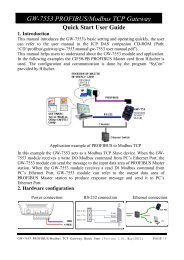
NEXCOM International Co., Ltd.<br />
Industrial Computing Solutions<br />
Fanless Computer<br />
<strong>NISE</strong> <strong>3500</strong>, <strong>NISE</strong> <strong>3500</strong>M Series<br />
User <strong>Manual</strong><br />
NEXCOM International Co., Ltd.<br />
Published December 2011<br />
www.nexcom.com
Contents<br />
Contents<br />
Preface<br />
Copyright .............................................................................................. iv<br />
Disclaimer .............................................................................................. iv<br />
Acknowledgements ............................................................................... iv<br />
Regulatory Compliance Statements ........................................................ iv<br />
Declaration of Conformity....................................................................... iv<br />
RoHS Compliance.................................................................................... v<br />
Warranty and RMA................................................................................. vi<br />
Safety Information .................................................................................vii<br />
Installation Recommendations.................................................................vii<br />
Safety Precautions..................................................................................viii<br />
Technical Support and Assistance............................................................ ix<br />
Conventions Used in this <strong>Manual</strong>............................................................ ix<br />
Global Service Contact Information.......................................................... x<br />
Package Contents...................................................................................xii<br />
Ordering Information.............................................................................xiii<br />
Chapter 1: Product Introduction<br />
Overview.................................................................................................1<br />
<strong>NISE</strong> <strong>3500</strong>...........................................................................................1<br />
<strong>NISE</strong> <strong>3500</strong>M........................................................................................2<br />
Hardware Specifications...........................................................................3<br />
Getting to Know <strong>NISE</strong> <strong>3500</strong> Series...........................................................5<br />
Front Panel of <strong>NISE</strong> <strong>3500</strong>.....................................................................5<br />
Front Panel of <strong>NISE</strong> <strong>3500</strong>M..................................................................5<br />
Rear Panel of <strong>NISE</strong> <strong>3500</strong>/<strong>3500</strong>M..........................................................6<br />
Mechanical Dimensions............................................................................7<br />
<strong>NISE</strong> <strong>3500</strong>/<strong>3500</strong>M...............................................................................7<br />
Chapter 2: Jumpers And Connectors<br />
Before You Begin.....................................................................................8<br />
Precautions..............................................................................................8<br />
Jumper Settings.......................................................................................9<br />
Locations of the Jumpers and Connectors..............................................10<br />
NISB <strong>3500</strong>.........................................................................................10<br />
Jumpers.................................................................................................12<br />
Clear CMOS......................................................................................12<br />
Connectors Pin Definitions.....................................................................13<br />
External I/O Interface - Front Panel.....................................................13<br />
USB Ports......................................................................................13<br />
eSATA Ports..................................................................................13<br />
IEEE1394b Connector (<strong>NISE</strong> <strong>3500</strong>M only)......................................14<br />
HDMI Connector (<strong>NISE</strong> <strong>3500</strong>M only).............................................14<br />
Status Indicators...........................................................................15<br />
LAN1/LAN2 Link/Active LED..........................................................15<br />
ATX Power On/Off Switch.............................................................16<br />
External I/O Interface - Rear Panel......................................................17<br />
Remote Power On/Off Switch.......................................................17<br />
PS/2 Keyboard/Mouse Port............................................................17<br />
9V-30V DC Input..........................................................................18<br />
GPIO Connector...........................................................................18<br />
Copyright © 2011 NEXCOM International Co., Ltd. All Rights Reserved. ii <strong>NISE</strong> <strong>3500</strong>, <strong>NISE</strong> <strong>3500</strong>M User <strong>Manual</strong>
Contents<br />
Serial Interface (COM 1 - COM 4).................................................19<br />
LAN Ports.....................................................................................21<br />
USB Ports......................................................................................22<br />
VGA Port......................................................................................22<br />
DVI-I Port......................................................................................23<br />
Speaker-out Jack...........................................................................23<br />
Mic-in Jack...................................................................................24<br />
Internal Connectors...........................................................................25<br />
ATX Power Output Connector.......................................................25<br />
Reset Connector...........................................................................25<br />
SMBus DATA/CLK Pin Header........................................................26<br />
LVDS Backlight Power Select.........................................................26<br />
LVDS Channel A Connector..........................................................27<br />
LVDS Channel B Connector...........................................................27<br />
LVDS Backlight Connector.............................................................28<br />
SATA Ports....................................................................................29<br />
SATA Power Connectors...............................................................29<br />
SATA DOM Power Connectors......................................................30<br />
USB Port Connector......................................................................30<br />
COM4 RI Pin Header.....................................................................31<br />
GPIO LED Connector.....................................................................31<br />
Line-in Connector.........................................................................32<br />
Internal Power/HDD/LAN Power/LAN Active LED...........................32<br />
Smart Fan Connectors..................................................................33<br />
COM5 Connector.........................................................................33<br />
Parallel Connector........................................................................34<br />
Chapter 3: System Setup<br />
Removing the Chassis Cover .................................................................35<br />
Installing a DIMM...................................................................................36<br />
Installing the CPU..................................................................................38<br />
Installing a SATA Hard Drive...................................................................41<br />
Installing a Half Length SATA DOM with SATA HD (<strong>NISE</strong><br />
<strong>3500</strong>P2/<strong>3500</strong>M2/<strong>3500</strong>M2 E)..................................................................44<br />
Installing a Full Length SATA DOM.........................................................46<br />
Wallmount Brackets...............................................................................48<br />
Chapter 4: BIOS Setup<br />
About BIOS Setup..................................................................................49<br />
When to Configure the BIOS..................................................................49<br />
Default Configuration............................................................................50<br />
Entering Setup.......................................................................................50<br />
Legends.................................................................................................50<br />
BIOS Setup Utility...................................................................................51<br />
Chapter 5: AMT Settings<br />
Enable Intel ® AMT in the AMI BIOS........................................................64<br />
Configure the Intel ® ME Setup...............................................................65<br />
Unconfigure AMT/ME............................................................................83<br />
Appendix A: Power Consumption......................... 85<br />
Appendix B: GPI/O Programming Guide............... 87<br />
Appendix C: Watchdog Timer Setting................... 88<br />
Appendix D: Intel Embedded AMT Management<br />
Express KVM...................................... 90<br />
Appendix E: Intel Manageability Command Tool -<br />
KVM.................................................... 97<br />
Appendix F: External Anti-vibration Kit................ 103<br />
Appendix G: <strong>NISE</strong><strong>3500</strong>iP2 Series with Isolated DC<br />
Input Design...................................... 107<br />
Copyright © 2011 NEXCOM International Co., Ltd. All Rights Reserved. iii <strong>NISE</strong> <strong>3500</strong>, <strong>NISE</strong> <strong>3500</strong>M User <strong>Manual</strong>
Preface<br />
Preface<br />
Copyright<br />
This publication, including all photographs, illustrations and software, is<br />
protected under international copyright laws, with all rights reserved. No<br />
part of this manual may be reproduced, copied, translated or transmitted<br />
in any form or by any means without the prior written consent from<br />
NEXCOM International Co., Ltd.<br />
Disclaimer<br />
The information in this document is subject to change without prior notice<br />
and does not represent commitment from NEXCOM International Co., Ltd.<br />
However, users may update their knowledge of any product in use by constantly<br />
checking its manual posted on our website: http://www.nexcom.<br />
com. NEXCOM shall not be liable for direct, indirect, special, incidental, or<br />
consequential damages arising out of the use of any product, nor for any<br />
infringements upon the rights of third parties, which may result from such<br />
use. Any implied warranties of merchantability or fitness for any particular<br />
purpose is also disclaimed.<br />
Acknowledgements<br />
<strong>NISE</strong> <strong>3500</strong>/<strong>3500</strong>M is a trademark of NEXCOM International Co., Ltd. All<br />
other product names mentioned herein are registered trademarks of their<br />
respective owners.<br />
Regulatory Compliance Statements<br />
This section provides the FCC compliance statement for Class B devices<br />
and describes how to keep the system CE compliant.<br />
Declaration of Conformity<br />
FCC<br />
This equipment has been tested and verified to comply with the limits for<br />
a Class B digital device, pursuant to Part 15 of FCC Rules. These limits are<br />
designed to provide reasonable protection against harmful interference<br />
when the equipment is operated in a commercial environment. This equipment<br />
generates, uses, and can radiate radio frequency energy and, if not<br />
installed and used in accordance with the instructions, may cause harmful<br />
interference to radio communications. Operation of this equipment in a<br />
residential area (domestic environment) is likely to cause harmful interference,<br />
in which case the user will be required to correct the interference<br />
(take adequate measures) at their own expense.<br />
CE<br />
The product(s) described in this manual complies with all applicable European<br />
Union (CE) directives if it has a CE marking. For computer systems to<br />
remain CE compliant, only CE-compliant parts may be used. Maintaining<br />
CE compliance also requires proper cable and cabling techniques.<br />
Copyright © 2011 NEXCOM International Co., Ltd. All Rights Reserved. iv <strong>NISE</strong> <strong>3500</strong>, <strong>NISE</strong> <strong>3500</strong>M User <strong>Manual</strong>
Preface<br />
RoHS Compliance<br />
NEXCOM RoHS Environmental Policy and Status<br />
Update<br />
NEXCOM is a global citizen for building the digital<br />
infrastructure. We are committed to providing green<br />
products and services, which are compliant with European<br />
Union RoHS (Restriction on Use of Hazardous Substance in Electronic<br />
Equipment) directive 2002/95/EU, to be your trusted green partner and to<br />
protect our environment.<br />
RoHS restricts the use of Lead (Pb) < 0.1% or 1,000ppm, Mercury (Hg)<br />
< 0.1% or 1,000ppm, Cadmium (Cd) < 0.01% or 100ppm, Hexavalent<br />
Chromium (Cr6+) < 0.1% or 1,000ppm, Polybrominated biphenyls (PBB)<br />
< 0.1% or 1,000ppm, and Polybrominated diphenyl Ethers (PBDE) < 0.1%<br />
or 1,000ppm.<br />
In order to meet the RoHS compliant directives, NEXCOM has established<br />
an engineering and manufacturing task force in to implement the introduction<br />
of green products. The task force will ensure that we follow the<br />
standard NEXCOM development procedure and that all the new RoHS<br />
components and new manufacturing processes maintain the highest<br />
industry quality levels for which NEXCOM are renowned.<br />
The model selection criteria will be based on market demand. Vendors and<br />
suppliers will ensure that all designed components will be RoHS compliant.<br />
How to recognize NEXCOM RoHS Products?<br />
For existing products where there are non-RoHS and RoHS versions, the<br />
suffix “(LF)” will be added to the compliant product name.<br />
All new product models launched after January 2006 will be RoHS compliant.<br />
They will use the usual NEXCOM naming convention.<br />
Copyright © 2011 NEXCOM International Co., Ltd. All Rights Reserved. v <strong>NISE</strong> <strong>3500</strong>, <strong>NISE</strong> <strong>3500</strong>M User <strong>Manual</strong>
Preface<br />
Warranty and RMA<br />
NEXCOM Warranty Period<br />
NEXCOM manufactures products that are new or equivalent to new in<br />
accordance with industry standard. NEXCOM warrants that products will<br />
be free from defect in material and workmanship for 2 years, beginning<br />
on the date of invoice by NEXCOM. HCP series products (Blade Server)<br />
which are manufactured by NEXCOM are covered by a three year warranty<br />
period.<br />
NEXCOM Return Merchandise Authorization (RMA)<br />
??<br />
Customers shall enclose the “NEXCOM RMA Service Form” with the<br />
returned packages.<br />
??<br />
Customers must collect all the information about the problems encountered<br />
and note anything abnormal or, print out any on-screen messages,<br />
and describe the problems on the “NEXCOM RMA Service Form” for<br />
the RMA number apply process.<br />
??<br />
Customers can send back the faulty products with or without accessories<br />
(manuals, cable, etc.) and any components from the card, such as<br />
CPU and RAM. If the components were suspected as part of the problems,<br />
please note clearly which components are included. Otherwise,<br />
NEXCOM is not responsible for the devices/parts.<br />
??<br />
Customers are responsible for the safe packaging of defective products,<br />
making sure it is durable enough to be resistant against further damage<br />
and deterioration during transportation. In case of damages occurred<br />
during transportation, the repair is treated as “Out of Warranty.”<br />
??<br />
Any products returned by NEXCOM to other locations besides the customers’<br />
site will bear an extra charge and will be billed to the customer.<br />
Repair Service Charges for Out-of-Warranty Products<br />
NEXCOM will charge for out-of-warranty products in two categories, one<br />
is basic diagnostic fee and another is component (product) fee.<br />
System Level<br />
??<br />
Component fee: NEXCOM will only charge for main components such<br />
as SMD chip, BGA chip, etc. Passive components will be repaired for<br />
free, ex: resistor, capacitor.<br />
??<br />
Items will be replaced with NEXCOM products if the original one cannot<br />
be repaired. Ex: motherboard, power supply, etc.<br />
??<br />
Replace with 3rd party products if needed.<br />
??<br />
If RMA goods can not be repaired, NEXCOM will return it to the customer<br />
without any charge.<br />
Board Level<br />
??<br />
Component fee: NEXCOM will only charge for main components, such<br />
as SMD chip, BGA chip, etc. Passive components will be repaired for<br />
free, ex: resistors, capacitors.<br />
? ? If RMA goods can not be repaired, NEXCOM will return it to the customer<br />
without any charge.<br />
Copyright © 2011 NEXCOM International Co., Ltd. All Rights Reserved. vi <strong>NISE</strong> <strong>3500</strong>, <strong>NISE</strong> <strong>3500</strong>M User <strong>Manual</strong>
Preface<br />
Warnings<br />
Read and adhere to all warnings, cautions, and notices in this guide and<br />
the documentation supplied with the chassis, power supply, and accessory<br />
modules. If the instructions for the chassis and power supply are inconsistent<br />
with these instructions or the instructions for accessory modules,<br />
contact the supplier to find out how you can ensure that your computer<br />
meets safety and regulatory requirements.<br />
Cautions<br />
Electrostatic discharge (ESD) can damage system components. Do the described<br />
procedures only at an ESD workstation. If no such station is available,<br />
you can provide some ESD protection by wearing an antistatic wrist<br />
strap and attaching it to a metal part of the computer chassis.<br />
Safety Information<br />
Before installing and using the device, note the following precautions:<br />
▪▪<br />
Read all instructions carefully.<br />
▪▪<br />
Do not place the unit on an unstable surface, cart, or stand.<br />
▪▪<br />
Follow all warnings and cautions in this manual.<br />
▪▪<br />
When replacing parts, ensure that your service technician uses parts<br />
specified by the manufacturer.<br />
▪▪<br />
Avoid using the system near water, in direct sunlight, or near a heating<br />
device.<br />
▪▪<br />
The load of the system unit does not solely rely for support from the<br />
rackmounts located on the sides. Firm support from the bottom is highly<br />
necessary in order to provide balance stability.<br />
▪▪<br />
The computer is provided with a battery-powered real-time clock circuit.<br />
There is a danger of explosion if battery is incorrectly replaced. Replace<br />
only with the same or equivalent type recommended by the manufacturer.<br />
Discard used batteries according to the manufacturer’s instructions.<br />
Installation Recommendations<br />
Ensure you have a stable, clean working environment. Dust and dirt can<br />
get into components and cause a malfunction. Use containers to keep<br />
small components separated.<br />
Adequate lighting and proper tools can prevent you from accidentally<br />
damaging the internal components. Most of the procedures that follow<br />
require only a few simple tools, including the following:<br />
• A Philips screwdriver<br />
• A flat-tipped screwdriver<br />
• A grounding strap<br />
• An anti-static pad<br />
Using your fingers can disconnect most of the connections. It is recommended<br />
that you do not use needlenose pliers to disconnect connections<br />
as these can damage the soft metal or plastic parts of the connectors.<br />
Copyright © 2011 NEXCOM International Co., Ltd. All Rights Reserved. vii <strong>NISE</strong> <strong>3500</strong>, <strong>NISE</strong> <strong>3500</strong>M User <strong>Manual</strong>
Preface<br />
Safety Precautions<br />
1. Read these safety instructions carefully.<br />
2. Keep this User <strong>Manual</strong> for later reference.<br />
3. Disconnect this equipment from any AC outlet before cleaning. Use a<br />
damp cloth. Do not use liquid or spray detergents for cleaning.<br />
4. For plug-in equipment, the power outlet socket must be located near<br />
the equipment and must be easily accessible.<br />
5. Keep this equipment away from humidity.<br />
6. Put this equipment on a stable surface during installation. Dropping<br />
it or letting it fall may cause damage.<br />
7. Do not leave this equipment in either an unconditioned environment<br />
or in a above 40 o C storage temperature as this may damage the<br />
equipment.<br />
8. The openings on the enclosure are for air convection to protect the<br />
equipment from overheating. DO NOT COVER THE OPENINGS.<br />
9. Make sure the voltage of the power source is correct before connecting<br />
the equipment to the power outlet.<br />
10. Place the power cord in a way so that people will not step on it. Do<br />
not place anything on top of the power cord. Use a power cord that<br />
has been approved for use with the product and that it matches the<br />
voltage and current marked on the product’s electrical range label.<br />
The voltage and current rating of the cord must be greater than the<br />
voltage and current rating marked on the product.<br />
11. All cautions and warnings on the equipment should be noted.<br />
12. If the equipment is not used for a long time, disconnect it from the<br />
power source to avoid damage by transient overvoltage.<br />
13. Never pour any liquid into an opening. This may cause fire or electrical<br />
shock.<br />
14. Never open the equipment. For safety reasons, the equipment should<br />
be opened only by qualified service personnel.<br />
15. If one of the following situations arises, get the equipment checked<br />
by service personnel:<br />
a. The power cord or plug is damaged.<br />
b. Liquid has penetrated into the equipment.<br />
c. The equipment has been exposed to moisture.<br />
d. The equipment does not work well, or you cannot get it to work<br />
according to the user’s manual.<br />
e. The equipment has been dropped and damaged.<br />
f. The equipment has obvious signs of breakage.<br />
16. Do not place heavy objects on the equipment.<br />
17. The unit uses a three-wire ground cable which is equipped with a<br />
third pin to ground the unit and prevent electric shock. Do not defeat<br />
the purpose of this pin. If your outlet does not support this kind of<br />
plug, contact your electrician to replace your obsolete outlet.<br />
18. CAUTION: DANGER OF EXPLOSION IF BATTERY IS INCORRECTLY<br />
REPLACED. REPLACE ONLY WITH THE SAME OR EQUIVALENT TYPE<br />
RECOMMENDED BY THE MANUFACTURER. DISCARD USED BATTER-<br />
IES ACCORDING TO THE MANUFACTURER’S INSTRUCTIONS.<br />
19. The computer is provided with CD drives that comply with the appropriate<br />
safety standards including IEC 60825.<br />
Copyright © 2011 NEXCOM International Co., Ltd. All Rights Reserved. viii <strong>NISE</strong> <strong>3500</strong>, <strong>NISE</strong> <strong>3500</strong>M User <strong>Manual</strong>
Preface<br />
Technical Support and Assistance<br />
Conventions Used in this <strong>Manual</strong><br />
1. For the most updated information of NEXCOM products, visit NEX-<br />
COM’s website at www.nexcom.com.<br />
2. For technical issues that require contacting our technical support team<br />
or sales representative, please have the following information ready<br />
before calling:<br />
– Product name and serial number<br />
– Detailed information of the peripheral devices<br />
– Detailed information of the installed software (operating system,<br />
version, application software, etc.)<br />
– A complete description of the problem<br />
– The exact wordings of the error messages<br />
Warning!<br />
1. Handling the unit: carry the unit with both hands and handle it with<br />
care.<br />
2. Maintenance: to keep the unit clean, use only approved cleaning products<br />
or clean with a dry cloth.<br />
3. CompactFlash: Turn off the unit’s power before inserting or removing a<br />
CompactFlash storage card.<br />
CAUTION!<br />
Warning: Information about certain situations, which if not<br />
observed, can cause personal injury. This will prevent injury to<br />
yourself when performing a task.<br />
Caution: Information to avoid damaging components or losing<br />
data.<br />
Note: Provides additional information to complete a task easily.<br />
Safety Warning: This equipment is intended for installation in a<br />
Restricted Access Location only.<br />
Copyright © 2011 NEXCOM International Co., Ltd. All Rights Reserved. ix <strong>NISE</strong> <strong>3500</strong>, <strong>NISE</strong> <strong>3500</strong>M User <strong>Manual</strong>
Preface<br />
Global Service Contact Information<br />
Headquarters<br />
Taiwan<br />
15F, No.920,Chung-Cheng Road, Zhonghe Dist.<br />
New Taipei City, Taiwan 23586, R.O.C.<br />
Tel: +886-2-8226-7786<br />
Fax: +886-2-8226-7782<br />
http://www.nexcom.com.tw<br />
USA<br />
3758 Spinnaker Court,<br />
Fremont, CA 94538, USA<br />
Tel: +1-510-656-2248<br />
Fax: +1-510-656-2158<br />
http://www.nexcom.com<br />
France<br />
Z.I. des Amandiers, 17, Rue des entrepreneurs<br />
78420 Carrières sur Seine, France<br />
Tel: +33 (0)1 71 51 10 20<br />
Fax: +33 (0)1 71 51 10 21<br />
http://www.nexcom.eu<br />
Germany<br />
Leopoldstrase Business Centre, Leopoldstrase 244 80807<br />
Munich, Germany<br />
Tel: +49-89-208039-278<br />
Fax: +49-89-208039-279<br />
http://www.nexcom.eu<br />
Italy<br />
Via Gaudenzio Ferrari 29, 21047 Saronno (VA) Italia<br />
Tel: +39 02 9628 0333<br />
Fax: +39 02 9619 8846<br />
http://www.nexcom.eu<br />
United Kingdom<br />
10 Vincent Avenue, Crownhill Business Centre<br />
Milton Keynes, Buckinghamshire, MK8 0AB<br />
United Kingdom<br />
Tel: +44-1908-267121<br />
Fax: +44-1908-262042<br />
http://www.nexcom.eu<br />
Copyright © 2011 NEXCOM International Co., Ltd. All Rights Reserved. x <strong>NISE</strong> <strong>3500</strong>, <strong>NISE</strong> <strong>3500</strong>M User <strong>Manual</strong>
Preface<br />
China-Beijing<br />
Room 301, Block E, Power Creative Building, No. 1<br />
Shangdi East Rd. Haidian Dist., Beijing, 100085, China<br />
Tel: +86-10-5885-6655<br />
Fax: +86-10-5885-1066<br />
http://www.nexcom.cn<br />
China-Shanghai Office<br />
Room 1505, Greenland He Chuang Building, No. 450<br />
Caoyang Rd. Shanghai, 200063, China<br />
Tel: +86-21-6150-8008<br />
Fax: +86-21-3251-6358<br />
http://www.nexcom.cn<br />
Japan<br />
9F, Tamachi Hara Bldg.,<br />
4-11-5, Shiba Minato-ku Tokyo,<br />
Japan 108-0014<br />
Tel: +81-3-5419-7830<br />
Fax: +81-3-5419-7832<br />
http://www.nexcom-jp.com<br />
China-Nanjing Office<br />
Room 1206, Hongde Building, No. 20 Yunnan Rd.<br />
Nanjing, 210018, China<br />
Tel: +86-25-8324-9606<br />
Fax: +86-25-8324-9685<br />
http://www.nexcom.cn<br />
China-Shenzhen Office<br />
Western Room 708, Block 210, Tairan Industry & Trading Place,<br />
Futian Area, Shenzhen, China 518040<br />
TEL: +86-755-833 27203<br />
FAX: +86-755-833 27213<br />
http://www.nexcom.cn<br />
Copyright © 2011 NEXCOM International Co., Ltd. All Rights Reserved. xi <strong>NISE</strong> <strong>3500</strong>, <strong>NISE</strong> <strong>3500</strong>M User <strong>Manual</strong>
Preface<br />
Package Contents<br />
Before continuing, verify that the <strong>NISE</strong> <strong>3500</strong> Series package that you received is complete. Your package should have all the items listed in the following<br />
table.<br />
Item Part Number Description Qty<br />
1 60233POW33X00 DC Power Cable 1<br />
2 6023344361X00 DB44 to 4x DB9 COM port cable 1<br />
3 6029900037X00 DOW CORNING 340 Silcone Heat Sink Compound(3g) 1<br />
4 4NCPM00203X00 2 Pin Phoenix Contact: MC 1.5/2-ST-3.81(1803578), 3.81mm pitch 1<br />
5 50311F0110X00 Flat Head Screw for HDD F3x5 ISO+NYLOK NIGP 4<br />
6 602DCD0269X00 NISB<strong>3500</strong> CD DRIVER VER:1.0 1<br />
7 7800000014X00 DVI-I TO VGA Adapter 1<br />
8 5060600087X00 Mylar for PCI bracket 1<br />
9 60177A0205X00 NISB<strong>3500</strong> Quick Reference Guide VER:A 1<br />
10 50311P0001X00 Plastic Screw for PCI card use 1<br />
11 60233MK202X00 PS/2 Y Cable for Keyboard / Mouse, L:150mm 1<br />
12 50322P0001X00 Plastic Nut for PCI card use 1<br />
Copyright © 2011 NEXCOM International Co., Ltd. All Rights Reserved. xii <strong>NISE</strong> <strong>3500</strong>, <strong>NISE</strong> <strong>3500</strong>M User <strong>Manual</strong>
Preface<br />
Ordering Information<br />
The following provides ordering information for <strong>NISE</strong> <strong>3500</strong> Series.<br />
• Barebone<br />
<strong>NISE</strong> <strong>3500</strong>M (P/N: 10J00<strong>3500</strong>01X0) RoHS Compliant<br />
- Intel ® Core i7/i5 Fanless System<br />
- 1 x PCI expansion slot<br />
<strong>NISE</strong> <strong>3500</strong> (P/N: 10J00<strong>3500</strong>00X0) RoHS Compliant<br />
- Intel ® Core i7/i5 Fanless System<br />
- 1 x PCI expansion slot<br />
<strong>NISE</strong> <strong>3500</strong>P2 (P/N: 10J00<strong>3500</strong>02X0) RoHS Compliant<br />
- Intel ® Core i7/i5 Fanless System<br />
- 2 x PCI expansion slots<br />
<strong>NISE</strong> <strong>3500</strong>M2 E (P/N: 10J00<strong>3500</strong>03X0) RoHS Compliant<br />
- Intel ® Core i7/i5 Fanless System<br />
- 1 x PCI expansion slot, 1 x PCIe expansion slot<br />
• 19V, 120W AC/DC Power Adapter w/o power cord<br />
(P/N: 7410120002X00)<br />
Copyright © 2011 NEXCOM International Co., Ltd. All Rights Reserved. xiii <strong>NISE</strong> <strong>3500</strong>, <strong>NISE</strong> <strong>3500</strong>M User <strong>Manual</strong>
Chapter 1: Product Introduction<br />
Chapter 1: Product Introduction<br />
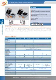
Overview<br />
<strong>NISE</strong> <strong>3500</strong><br />
Front<br />
Rear<br />
Key Features<br />
• Intel ® Core i7/i5 socket processor<br />
• Mobile Intel ® QM57 PCH<br />
• Dual Intel ® Gigabit Ethernet ports<br />
• Dual VGA or VGA/DVI Independent Display<br />
• 3x RS232 and 1x RS232/422/485 with Auto Flow<br />
Control<br />
• 4 x Digital Input, 4 x Digital Output<br />
• Onboard DC to DC power design to support<br />
9V to 30V DC power input<br />
• Supports ATX power mode and PXE/WOL<br />
Copyright © 2011 NEXCOM International Co., Ltd. All Rights Reserved. 1 <strong>NISE</strong> <strong>3500</strong>, <strong>NISE</strong> <strong>3500</strong>M User <strong>Manual</strong>
Chapter 1: Product Introduction<br />
<strong>NISE</strong> <strong>3500</strong>M<br />
Front<br />
Rear<br />
Key Features<br />
• Intel ® Core i7/i5 socket processor<br />
• Mobile Intel ® QM57 PCH<br />
• Dual Intel ® Gigabit Ethernet ports<br />
• Dual VGA or VGA/DVI or DVI/HDMI Independent<br />
Display<br />
• 3x RS232 and 1x RS232/422/485 with Auto Flow<br />
Control<br />
• 3x IEEE1394b ports, 2x eSATA<br />
• Onboard DC to DC power design to support 9V to 30V<br />
DC power input<br />
• Supports ATX power mode and PXE/WOL<br />
Copyright © 2011 NEXCOM International Co., Ltd. All Rights Reserved. 2 <strong>NISE</strong> <strong>3500</strong>, <strong>NISE</strong> <strong>3500</strong>M User <strong>Manual</strong>
Chapter 1: Product Introduction<br />
Hardware Specifications<br />
Main Board<br />
• NISB <strong>3500</strong><br />
• Onboard Mobile Intel ® QM57 Platform Controller Hub<br />
• Supports Intel ® Core i7-620M PGA Processor (2.66GHz, 4M Cache)<br />
• Supports Intel ® Core i5-520M PGA Processor (2.4GHz, 3M Cache)<br />
• Supports Intel ® P4500 PGA Processor (1.86GHz, 2M Cache)<br />
Main Memory<br />
• 2x 240-pin memory DIMM, up to 4GB DDR3 800/1066MHz SDRAM,<br />
unbuffered and non-ECC<br />
Note: The actual memory size is dynamic. It is based on the OS I/O resource<br />
allocation.<br />
I/O Interface - Front<br />
• ATX power on/off switch<br />
• HDD Access / Power status LEDs<br />
• 2 x USB2.0 ports<br />
• 2 x eSATA ports<br />
• 3 x IEEE1394b ports (<strong>NISE</strong> <strong>3500</strong>M only)<br />
• 1 x HDMI port (<strong>NISE</strong> <strong>3500</strong>M only)<br />
I/O Interface - Rear<br />
• 2-pin Remote Power on/off switch<br />
• 9 ~ 30V DC input<br />
• 1 x PS/2 for Keyboard/Mouse<br />
• 1 x DB15 male connector for GPIO (4x digital-input and 4x digital-output)<br />
• 1 x DB44 Serial Port for 4x RS232<br />
(COM2: RS232/422/485 with Auto Flow Control)<br />
• 2 x Gbe LAN ports<br />
• 4 x USB2.0 ports<br />
• 1 x DB15 VGA port<br />
• 1 x DVI-I Port<br />
• 1 x Speaker-out<br />
• 1 x Mic-in<br />
Device<br />
• 1 x 2.5” HDD drive bay<br />
Expansion<br />
• One PCI expansion<br />
• Max. Supported Add-on Card Length: 169mm<br />
Copyright © 2011 NEXCOM International Co., Ltd. All Rights Reserved. 3 <strong>NISE</strong> <strong>3500</strong>, <strong>NISE</strong> <strong>3500</strong>M User <strong>Manual</strong>
Chapter 1: Product Introduction<br />
Power Requirements<br />
• ATX power mode<br />
• Onboard DC to DC power support from 9V to 30V DC<br />
• Optional power adapter<br />
Dimensions<br />
• 195mm (W) x 268mm (D) x 80mm (H) (7.7” x 10.5” x 3.1”)<br />
Construction<br />
• Aluminum chassis with fanless design<br />
Environment<br />
• Operating temperature:<br />
Ambient with airflow: -5°C to 55°C<br />
(According to IEC60068-2-1, IEC60068-2-2, IEC60068-2-14)<br />
• Storage temperature: -20°C to 80°C<br />
• Relative humidity: 10% to 93% (Non-Condensing)<br />
Certifications<br />
• CE approval<br />
• FCC Class A<br />
Copyright © 2011 NEXCOM International Co., Ltd. All Rights Reserved. 4 <strong>NISE</strong> <strong>3500</strong>, <strong>NISE</strong> <strong>3500</strong>M User <strong>Manual</strong>
Chapter 1: Product Introduction<br />
Getting to Know <strong>NISE</strong> <strong>3500</strong> Series<br />
Front Panel of <strong>NISE</strong> <strong>3500</strong><br />
LAN LEDs<br />
Power LED<br />
Front Panel of <strong>NISE</strong> <strong>3500</strong>M<br />
LAN LEDs<br />
Power LED<br />
Power on/off<br />
switch<br />
Power on/off<br />
switch<br />
USB<br />
eSATA<br />
HDD LED<br />
USB eSATA<br />
1394b<br />
HDD LED<br />
HDMI<br />
USB<br />
Used to connect USB 2.0/1.1 devices.<br />
eSATA<br />
Used to connect eSATA devices.<br />
IEEE1394b<br />
Used to connect IEEE1394b devices.<br />
HDMI<br />
Used to connect devices that support HDMI.<br />
Power LED<br />
Indicates the power status of the system.<br />
HDD LED<br />
Indicates the status of the hard drive.<br />
LAN LEDs<br />
Indicate the status of the LAN ports.<br />
Power On/Off Switch<br />
Press to power-on or power-off the system.<br />
Copyright © 2011 NEXCOM International Co., Ltd. All Rights Reserved. 5 <strong>NISE</strong> <strong>3500</strong>, <strong>NISE</strong> <strong>3500</strong>M User <strong>Manual</strong>
Chapter 1: Product Introduction<br />
Rear Panel of <strong>NISE</strong> <strong>3500</strong>/<strong>3500</strong>M<br />
PS/2 KB/Mouse<br />
Output for<br />
remote power<br />
on/off swtich<br />
GPIO<br />
LAN<br />
COM1-COM4<br />
9V-30V<br />
USB<br />
DC Input<br />
VGA<br />
Speaker-out<br />
1 expansion<br />
card slot<br />
Output for Remote Power On/Off Switch<br />
Used to connect a remote to power on/off the system.<br />
PS/2 Keyboard/Mouse<br />
Used to connect a PS/2 keyboard and PS/2 mouse via a cable.<br />
9V-30V DC Input<br />
Used to plug a DC power cord.<br />
GPIO<br />
The GPIO connector supports 4 digital input and 4 digital output.<br />
COM1 to COM4<br />
The DB44 port supports 3 RS232 and 1 RS232/422/485 compatible serial<br />
devices.<br />
LAN<br />
Used to connect the system to a local area network.<br />
USB<br />
Used to connect USB 2.0/1.1 devices.<br />
VGA<br />
Used to connect an analog VGA monitor.<br />
DVI<br />
Used to connect a digital LCD panel.<br />
Speaker-out<br />
Used to connect a headphone or a speaker.<br />
Mic-in<br />
Used to connect an external microphone.<br />
Expansion Slot<br />
One PCI expansion slot.<br />
Copyright © 2011 NEXCOM International Co., Ltd. All Rights Reserved. 6 <strong>NISE</strong> <strong>3500</strong>, <strong>NISE</strong> <strong>3500</strong>M User <strong>Manual</strong>
Chapter 1: Product Introduction<br />
Mechanical Dimensions<br />
<strong>NISE</strong> <strong>3500</strong>/<strong>3500</strong>M<br />
184.00<br />
224.00<br />
264.00<br />
268.00<br />
195.00<br />
207.00<br />
219.00<br />
80.00<br />
86.00<br />
Copyright © 2011 NEXCOM International Co., Ltd. All Rights Reserved. 7 <strong>NISE</strong> <strong>3500</strong>, <strong>NISE</strong> <strong>3500</strong>M User <strong>Manual</strong>
Chapter 2: Jumpers and Connectors<br />
This chapter describes how to set the jumpers on the motherboard. Note<br />
that the following procedures are generic for all <strong>NISE</strong> <strong>3500</strong> series.<br />
Before You Begin<br />
• Ensure you have a stable, clean working environment. Dust and dirt can<br />
get into components and cause a malfunction. Use containers to keep<br />
small components separated.<br />
• Adequate lighting and proper tools can prevent you from accidentally<br />
damaging the internal components. Most of the procedures that follow<br />
require only a few simple tools, including the following:<br />
• A Philips screwdriver<br />
• A flat-tipped screwdriver<br />
• A set of jewelers Screwdrivers<br />
• A grounding strap<br />
• An anti-static pad<br />
• Using your fingers can disconnect most of the connections. It is recommended<br />
that you do not use needle-nosed pliers to disconnect connections<br />
as these can damage the soft metal or plastic parts of the connectors.<br />
• Before working on internal components, make sure that the power<br />
is off. Ground yourself before touching any internal components, by<br />
touching a metal object. Static electricity can damage many of the electronic<br />
components. Humid environment tend to have less static electricity<br />
than dry environments. A grounding strap is warranted whenever<br />
danger of static electricity exists.<br />
Precautions<br />
Computer components and electronic circuit boards can be damaged by<br />
discharges of static electricity. Working on the computers that are still connected<br />
to a power supply can be extremely dangerous.<br />
Follow the guidelines below to avoid damage to your computer or yourself:<br />
• Always disconnect the unit from the power outlet whenever you are<br />
working inside the case.<br />
• If possible, wear a grounded wrist strap when you are working inside<br />
the computer case. Alternatively, discharge any static electricity by<br />
touching the bare metal chassis of the unit case, or the bare metal body<br />
of any other grounded appliance.<br />
• Hold electronic circuit boards by the edges only. Do not touch the components<br />
on the board unless it is necessary to do so. Don’t flex or stress<br />
the circuit board.<br />
• Leave all components inside the static-proof packaging that they<br />
shipped with until they are ready for installation.<br />
• Use correct screws and do not over tighten screws.<br />
Copyright © 2011 NEXCOM International Co., Ltd. All Rights Reserved. 8 <strong>NISE</strong> <strong>3500</strong>, <strong>NISE</strong> <strong>3500</strong>M User <strong>Manual</strong>
Jumper Settings<br />
A jumper is the simplest kind of electric switch. It consists of two metal<br />
pins and a cap. When setting the jumpers, ensure that the jumper caps are<br />
placed on the correct pins. When the jumper cap is placed on both pins,<br />
the jumper is short. If you remove the jumper cap, or place the jumper<br />
cap on just one pin, the jumper is open.<br />
Refer to the illustrations below for examples of what the 2-pin and 3-pin<br />
jumpers look like when they are short (on) and open (off).<br />
Two-Pin Jumpers: Open (Left) and Short (Right)<br />
Three-Pin Jumpers: Pins 1 and 2 Are Short<br />
Copyright © 2011 NEXCOM International Co., Ltd. All Rights Reserved. 9 <strong>NISE</strong> <strong>3500</strong>, <strong>NISE</strong> <strong>3500</strong>M User <strong>Manual</strong>
1<br />
1<br />
1<br />
Locations of the Jumpers and Connectors<br />
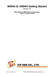
NISB <strong>3500</strong><br />
The figure below is the top view of the NISB <strong>3500</strong> main board which is the main board used in the <strong>NISE</strong> <strong>3500</strong> Series system. It shows the locations of the<br />
jumpers and connectors.<br />
J3<br />
CN1<br />
CON1<br />
J1<br />
J18<br />
J2<br />
J4<br />
SW1<br />
LED1<br />
LED2<br />
CN2<br />
J5<br />
LED3<br />
J6<br />
JP2 JP1<br />
J7<br />
CN3<br />
J9<br />
J8<br />
CN4<br />
J10<br />
CN6<br />
CN5<br />
J11<br />
CN9<br />
BAT1<br />
JP3<br />
CN7<br />
CN8<br />
J12<br />
CON2<br />
CN11<br />
J15<br />
JP4<br />
J13<br />
DIMM1<br />
DIMM2<br />
J14<br />
CN10<br />
Copyright © 2011 NEXCOM International Co., Ltd. All Rights Reserved. 10 <strong>NISE</strong> <strong>3500</strong>, <strong>NISE</strong> <strong>3500</strong>M User <strong>Manual</strong>
9<br />
The figure below is the bottom view of the NISB <strong>3500</strong> main board.<br />
J17<br />
J16<br />
CN16<br />
CN17<br />
CN12<br />
CN15<br />
CN13 CN14<br />
Copyright © 2011 NEXCOM International Co., Ltd. All Rights Reserved. 11 <strong>NISE</strong> <strong>3500</strong>, <strong>NISE</strong> <strong>3500</strong>M User <strong>Manual</strong>
Jumpers<br />
Clear CMOS<br />
Connector size: 1x3 3-pin header, 2.54 mm pitch<br />
Connector location: JP4<br />
1 3<br />
Pin<br />
Settings<br />
1-2 On *Normal<br />
2-3 On CMOS Clear<br />
1-2 On: default<br />
Pin<br />
Definition<br />
1 RTCRST#_PU<br />
2 RTCRST#<br />
3 CLR_CMOS<br />
Copyright © 2011 NEXCOM International Co., Ltd. All Rights Reserved. 12 <strong>NISE</strong> <strong>3500</strong>, <strong>NISE</strong> <strong>3500</strong>M User <strong>Manual</strong>
Connector Pin Definitions<br />
External I/O Interface - Front Panel<br />
USB Ports<br />
Connector type: Dual USB port<br />
Connector location: CN10<br />
eSATA Ports<br />
Connector type: eSATA port<br />
Connector location: CON2A and CON2B<br />
Pin Definition Pin Definition<br />
1 +5V 7 USB1+<br />
2 USB0- 8 GND<br />
3 USB0+ 22 GND<br />
4 GND 23 GND<br />
5 +5V 26 GND<br />
6 USB1- 27 GND<br />
Pin Definition Pin Definition<br />
1 GND 5 SATA_RXN4<br />
2 SATA_TXP4 6 SATA_RXP4<br />
3 SATA_TXN4 7 GND<br />
4 GND<br />
Copyright © 2011 NEXCOM International Co., Ltd. All Rights Reserved. 13 <strong>NISE</strong> <strong>3500</strong>, <strong>NISE</strong> <strong>3500</strong>M User <strong>Manual</strong>
IEEE1394b Connector (<strong>NISE</strong> <strong>3500</strong>M only)<br />
Connector type: 1394<br />
Connector location: J7, J10 and J11<br />
HDMI Connector (<strong>NISE</strong> <strong>3500</strong>M only)<br />
Connector type: HDMI<br />
Connector location: J6<br />
19<br />
1<br />
Pin Description Pin Description<br />
1 TB2N 2 TB2P<br />
3 TA2N 4 TA2P<br />
5 1394B_SG_2 6 GND<br />
7 NC 8 +12V<br />
9 GND<br />
18<br />
2<br />
Pin Definition Pin Definition<br />
1 HDMID_D2P 2 GND<br />
3 HDMID_D2N 4 HDMID_D1P<br />
5 GND 6 HDMID_D1N<br />
7 HDMID_D0P 8 GND<br />
9 HDMID_D0N 10 HDMID_LKP<br />
11 GND 12 HDMID_LKN<br />
13 NC 14 NC<br />
15 HDMID_CTL_CLK 16 HDMID_CTL_SDA<br />
17 GND 18 +5V<br />
19 HDP<br />
Copyright © 2011 NEXCOM International Co., Ltd. All Rights Reserved. 14 <strong>NISE</strong> <strong>3500</strong>, <strong>NISE</strong> <strong>3500</strong>M User <strong>Manual</strong>
Status Indicators<br />
PWR<br />
LAN1/LAN2 Link/Active LED<br />
Connector location: LED1 and LED2<br />
LINK1<br />
LINK2<br />
HDD<br />
Status<br />
LED Color<br />
PWR Green<br />
HDD Yellow<br />
ACT1<br />
ACT2<br />
Pin<br />
Definition<br />
C1 LAN2_LINK_N<br />
C2 LAN2_ACT_N<br />
A1 LAN2_LINK_P<br />
A2 LAN2_ACT_P<br />
Copyright © 2011 NEXCOM International Co., Ltd. All Rights Reserved. 15 <strong>NISE</strong> <strong>3500</strong>, <strong>NISE</strong> <strong>3500</strong>M User <strong>Manual</strong>
ATX Power On/Off Switch<br />
Connector location: SW1<br />
Pin<br />
Definition<br />
On Blue light<br />
Off Red light<br />
Pin Definition Pin Definition<br />
1 GND 2 PBT_PU<br />
3 PBT_PU 4 GND<br />
A1 PWRLED_N C1 PWRLED_P<br />
Copyright © 2011 NEXCOM International Co., Ltd. All Rights Reserved. 16 <strong>NISE</strong> <strong>3500</strong>, <strong>NISE</strong> <strong>3500</strong>M User <strong>Manual</strong>
External I/O Interface - Rear Panel<br />
Connector type: 2-pin switch<br />
Connector location: J3<br />
PS/2 Keyboard/Mouse Port<br />
Connector type: PS/2, Mini-DIN-6, JST-2.0mm-M-180<br />
Connector location: J5<br />
1 2<br />
6 5<br />
4<br />
3<br />
6<br />
1<br />
Pin<br />
Definition<br />
1 GND<br />
2 PBT_PU<br />
2<br />
1<br />
Pin Definition Pin Definition<br />
1 5VSB 2 KDAT<br />
3 KCLK 4 MDAT<br />
5 MCLK 6 GND<br />
Copyright © 2011 NEXCOM International Co., Ltd. All Rights Reserved. 17 <strong>NISE</strong> <strong>3500</strong>, <strong>NISE</strong> <strong>3500</strong>M User <strong>Manual</strong>
9V-30V DC Input<br />
Connector type: POWER-F-90<br />
Connector location: CN1<br />
GPIO Connector<br />
(4 digital input and 4 digital output)<br />
Connector type: DB-15 port, 2x5 10-pin header, 2.0 mm-M-180<br />
Connector location: JP2<br />
1 2<br />
3<br />
4<br />
1 2<br />
1 5<br />
Pin Definition Pin Definition<br />
1 VIN 2 VIN<br />
3 GND 4 GND<br />
5 GND<br />
9 10<br />
11 15<br />
Pin Definition Pin Definition<br />
1 VCC5 2 SIO_GPI20<br />
3 SIO_GPI21 4 SIO_GPI22<br />
5 SIO_GPI23 6 GND<br />
7 SIO_GPO24 8 SIO_GPO25<br />
9 SIO_GPO26 10 SIO_GPO27<br />
Copyright © 2011 NEXCOM International Co., Ltd. All Rights Reserved. 18 <strong>NISE</strong> <strong>3500</strong>, <strong>NISE</strong> <strong>3500</strong>M User <strong>Manual</strong>
Serial Interface (COM 1 - COM 4)<br />
Connector type: 44-pin D-Sub, 2x22 (12.55mm x 53.04mm)<br />
Connector location: CN4<br />
30<br />
15<br />
44<br />
1 16<br />
The 44-pin D-Sub connector is used to connect 4 external serial devices.<br />
Use the COM ports on the provided “DB44 to 4x DB9 COM port cable”<br />
(included in the package) to connect the devices.<br />
6<br />
44-pin D-Sub<br />
1 5<br />
COM port<br />
9<br />
31<br />
Pin Definition Pin Definition<br />
1 CN10_1 2 CN10_2<br />
3 CN10_3 4 CN10_4<br />
5 GND 6 CN10_6<br />
7 CN10_7 8 CN10_8<br />
9 CN10_9 10 GND<br />
11 CN10_11 12 CN10_12<br />
13 CN10_13 14 CN10_14<br />
15 GND 16 CN10_16<br />
17 CN10_17 18 CN10_18<br />
19 CN10_19 20 GND<br />
21 CN10_21 22 CN10_22<br />
23 CN10_23 24 CN10_24<br />
25 GND 26 CN10_26<br />
27 CN10_27 28 CN10_28<br />
29 CN10_29 30 GND<br />
31 CN10_31 32 CN10_32<br />
33 CN10_33 34 CN10_34<br />
35 GND 36 CN10_36<br />
37 CN10_37 38 CN10_38<br />
39 SP4_RI_TI 40 GND<br />
41 NC 42 NC<br />
43 NC 44 NC<br />
Copyright © 2011 NEXCOM International Co., Ltd. All Rights Reserved. 19 <strong>NISE</strong> <strong>3500</strong>, <strong>NISE</strong> <strong>3500</strong>M User <strong>Manual</strong>
COM1 (RS232) labelled “A“ on DB9 Cable Connector<br />
DB44 Pin # DB9 Pin # Def. DB44 Pin # DB9 Pin # Def.<br />
1 1 DCD1 2 2 RXD1<br />
3 3 TXD1 4 4 DTR1<br />
5 5 GND 6 6 DSR1<br />
7 7 RTS1 8 8 CTS1<br />
9 9 RI1 10 GND<br />
COM4 labelled “D“ on DB9 Cable Connector<br />
DB44 Pin # DB9 Pin # Def. DB44 Pin # DB9 Pin # Def.<br />
31 1 DCD4 32 2 RXD1<br />
33 3 TXD4 34 4 DTR1<br />
35 5 GND 36 6 DSR1<br />
37 7 RTS4 38 8 CTS1<br />
39 9 RI4 40 GND<br />
COM2 (RS232) labelled “B“ on DB9 Cable Connector<br />
DB44 Pin # DB9 Pin # Def. DB44 Pin # DB9 Pin # Def.<br />
11 1 DCD2 12 2 RXD2<br />
13 3 TXD2 14 4 DTR2<br />
15 5 GND 16 6 DSR2<br />
17 7 RTS2 18 8 CTS2<br />
19 9 RI2 20 GND<br />
Note: Pin 39 is defined as an external power source, which can be selected for 5V<br />
or 12V using JP9.<br />
COM2 (RS422) labelled “B“ on DB9 Cable Connector<br />
DB44 Pin # DB9 Pin # Def. DB44 Pin # DB9 Pin # Def.<br />
11 1 TXD- 12 2 TXD+<br />
13 3 RXD+ 14 4 RXD-<br />
15 5 GND 16 6 RTS-<br />
17 7 RTS# 18 8 CTS+<br />
19 9 CTS- 20 GND<br />
COM3 (RS232) labelled “C“ on DB9 Cable Connector<br />
DB44 Pin # DB9 Pin # Def. DB44 Pin # DB9 Pin # Def.<br />
21 1 DCD3 22 2 RXD3<br />
23 3 TXD3 24 4 DTR3<br />
25 5 GND 26 6 DSR3<br />
27 7 RTS3 28 8 CTS3<br />
29 9 RI3 30 GND<br />
Copyright © 2011 NEXCOM International Co., Ltd. All Rights Reserved. 20 <strong>NISE</strong> <strong>3500</strong>, <strong>NISE</strong> <strong>3500</strong>M User <strong>Manual</strong>
COM2 (RS485) labelled “B“ on DB9 Cable Connector<br />
DB44 Pin # DB9 Pin # Def. DB44 Pin # DB9 Pin # Def.<br />
11 1 TXD- 12 2 TXD+<br />
RXD-<br />
RXD+<br />
13 3 Reserved 14 4 Reserved<br />
15 5 Reserved 16 6 Reserved<br />
17 7 Reserved 18 8 Reserved<br />
19 9 Reserved 20 Reserved<br />
LAN Ports<br />
Connector type: RJ45 port with LEDs<br />
Connector location: CN3B and CN6B<br />
Act<br />
Link<br />
Act<br />
Status<br />
Orange Data Activity<br />
Blinking<br />
Off No Acitivity<br />
Link<br />
Status<br />
Green<br />
Linked<br />
Always Lighted<br />
Off No Link<br />
Pin Definition Pin Definition<br />
09 LAN1_M0P 10 LAN1_M0N<br />
11 LAN1_M1P 12 LAN1_M2P<br />
13 LAN1_M2N 14 LAN1_M1N<br />
15 LAN1_M3P 16 LAN1_M3N<br />
17 LAN1_LED1P 18 LAN1_LED_ACT#<br />
19 LAN1_LED2P 20 LAN1_LINK#<br />
21 GND 24 GND<br />
25 GND 28 GND<br />
Copyright © 2011 NEXCOM International Co., Ltd. All Rights Reserved. 21 <strong>NISE</strong> <strong>3500</strong>, <strong>NISE</strong> <strong>3500</strong>M User <strong>Manual</strong>
USB Ports<br />
Connector type: Dual USB port<br />
Connector location: CN3A and CN6A<br />
VGA Port<br />
Connector type: DB-15 port, 15-pin D-Sub<br />
Connector location: CN9B<br />
5<br />
1<br />
15<br />
11<br />
Pin Definition Pin Definition<br />
1 +5V 7 USB1+<br />
2 USB0- 8 GND<br />
3 USB0+ 22 GND<br />
4 GND 23 GND<br />
5 +5V 26 GND<br />
6 USB1- 27 GND<br />
Pin Description Pin Description Pin Description<br />
1 RED_VGA 2 GREEN_VGA 3 BLUE_VGA<br />
4 DVI_GND 5 DVI_GND 6 DVI_GND<br />
7 DVI_GND 8 DVI_GND 9 VGA_+5V<br />
10 DVI_GND 11 DVI_GND 12 DATA_V<br />
13 HS_VGA 14 VS_VGA 15 CLK_V<br />
MH3 DVI_GND MH4 DVI_GND<br />
Copyright © 2011 NEXCOM International Co., Ltd. All Rights Reserved. 22 <strong>NISE</strong> <strong>3500</strong>, <strong>NISE</strong> <strong>3500</strong>M User <strong>Manual</strong>
DVI-I Port<br />
Connector type: 29-pin D-Sub Female 90°<br />
Connector location: CN9A<br />
Speaker-out Jack<br />
Connector type: 5-pin jack<br />
Connector location: CN11B<br />
1<br />
8<br />
17<br />
24<br />
Pin Function Pin Function<br />
01 HDMI_DATA2_N 2 HDMI_DATA2_P<br />
03 DVI_GND 4 NC<br />
05 NC 6 HDMI_CTL_CLK<br />
07 HDMI_CTL_SDA 8 DC_VSYNC_VGA<br />
09 HDMI_DATA1_N 10 HDMI_DATA1_P<br />
11 DVI_GND 12 NC<br />
13 NC 14 HDMIC_PWR_S<br />
15 DVI_GND 16 HDMIC_HPDET<br />
17 HDMI_DATA0_N 18 HDMI_DATA0_P<br />
19 DVI_GND 20 DC_DATA_VGA<br />
21 DC_CLK_VGA 22 NC<br />
23 HDMI_LKP 24 HDMI_LKN<br />
C1 DC_RED_VGA C2 DC_GREEN_VGA<br />
C3 DC_BLUE_VGA C4 DC_HSYNC_VGA<br />
C5A DVI_GND C5B DVI_GND<br />
Pin<br />
Definition<br />
1 GND<br />
2 SPK_Out_R<br />
3 NC<br />
4 NC<br />
5 SPK_Out_L<br />
Copyright © 2011 NEXCOM International Co., Ltd. All Rights Reserved. 23 <strong>NISE</strong> <strong>3500</strong>, <strong>NISE</strong> <strong>3500</strong>M User <strong>Manual</strong>
Mic-in Jack<br />
Connector size: 5-pin jack, 25.9x12.6x17.0mm<br />
Connector location: CN11A<br />
Pin<br />
Definition<br />
1 AU_GND<br />
2 MIC_OUT-L<br />
3 AU_GND<br />
4 MIC_JD1<br />
5 MIC_OUT-R<br />
Copyright © 2011 NEXCOM International Co., Ltd. All Rights Reserved. 24 <strong>NISE</strong> <strong>3500</strong>, <strong>NISE</strong> <strong>3500</strong>M User <strong>Manual</strong>
Internal Connectors<br />
DC Power Output Connector<br />
Connector type: 2x2 Aux power connector<br />
Connector location: CON1<br />
Reset Connector<br />
Connector type: 1x2 2-pin header, JST 2.5mm-M-90<br />
Connector location: J2<br />
1<br />
3<br />
1<br />
2<br />
2<br />
4<br />
Pin<br />
Definition<br />
1 GND<br />
2 GND<br />
3 VIN<br />
4 VIN<br />
Pin<br />
Definition<br />
1 RESET#<br />
2 GND<br />
Copyright © 2011 NEXCOM International Co., Ltd. All Rights Reserved. 25 <strong>NISE</strong> <strong>3500</strong>, <strong>NISE</strong> <strong>3500</strong>M User <strong>Manual</strong>
SMBus DATA/CLK Pin Header<br />
Connector type: 1x3 3-pin header 2.54mm-M-180<br />
Connector location: J8<br />
LVDS Backlight Power Select<br />
Connector type: 1x3 3-pin header 2.54mm-M-180<br />
Connector location: JP3<br />
1<br />
3<br />
Pin<br />
Definition<br />
1 SMB_CLK<br />
2 SMB_DATA<br />
3 GND<br />
1<br />
3<br />
Pin<br />
Definition<br />
1 VCC5<br />
2 PANEL1_VDD<br />
3 VCC3<br />
*Default: 2-3<br />
Copyright © 2011 NEXCOM International Co., Ltd. All Rights Reserved. 26 <strong>NISE</strong> <strong>3500</strong>, <strong>NISE</strong> <strong>3500</strong>M User <strong>Manual</strong>
LVDS Channel A Connector<br />
Connector type: LCD-1.25mm-M-180<br />
Connector location: CN7<br />
LVDS Channel B Connector<br />
Connector type: LCD-1.25mm-M-180<br />
Connector location: CN8<br />
MH1<br />
MH1<br />
1<br />
19<br />
1<br />
19<br />
2<br />
20<br />
2<br />
20<br />
MH2<br />
MH2<br />
Pin Definition Pin Definition<br />
1 L_DDC_CLK 2 L_DDC_DATA<br />
3 VDD 4 LA_DATAP0<br />
5 LA_DATAP3 6 LA_DATAN0<br />
7 LA_DATAN3 8 VDD<br />
9 GND_LVDS 10 LA_DATAP1<br />
11 LA_CLKP 12 LA_DATAN1<br />
13 LA_CLKN 14 GND_LVDS<br />
15 GND_LVDS 16 PANEL1_BACKLIGHT<br />
17 LA_DATAP2 18 PANEL1_BACKLIGHT<br />
19 LA_DATAN2 20 GND_LVDS<br />
Pin Definition Pin Definition<br />
1 L_DDC_CLK 2 L_DDC_DATA<br />
3 VDD 4 LB_DATAP0<br />
5 LB_DATAP3 6 LB_DATAN0<br />
7 LB_DATAN3 8 VDD<br />
9 GND_LVDS 10 LB_DATAP1<br />
11 LB_CLKP 12 LB_DATAN1<br />
13 LB_CLKN 14 GND_LVDS<br />
15 GND_LVDS 16 PANEL1_BACKLIGHT<br />
17 LB_DATAP2 18 PANEL1_BACKLIGHT<br />
19 LB_DATAN2 20 GND_LVDS<br />
Copyright © 2011 NEXCOM International Co., Ltd. All Rights Reserved. 27 <strong>NISE</strong> <strong>3500</strong>, <strong>NISE</strong> <strong>3500</strong>M User <strong>Manual</strong>
LVDS Backlight Connector<br />
Connector type: 1x7 7-pin header JST-2.5mm-M-180<br />
Connector location: J13<br />
7<br />
1<br />
Pin<br />
Definition<br />
1 VCC5<br />
2 PANEL1_BACKLIGHT<br />
3 PANEL1_BACKLIGHT<br />
4 L_BKLTCTL_R<br />
5 GND<br />
6 GND<br />
7 L_BKLTEN<br />
Copyright © 2011 NEXCOM International Co., Ltd. All Rights Reserved. 28 <strong>NISE</strong> <strong>3500</strong>, <strong>NISE</strong> <strong>3500</strong>M User <strong>Manual</strong>
SATA Ports<br />
Connector type: Standard Serial ATAII 7P (1.27mm, SATA-M-180)<br />
Connector location: CN12 and CN13<br />
1 7<br />
Pin<br />
Definition<br />
1 GND<br />
2 SATA_TXP1<br />
3 SATA_TXN1<br />
4 GND<br />
5 SATA_RXN1<br />
6 SATA_RXP1<br />
7 GND<br />
SATA Power Connectors<br />
Connector type: 4-pin Wafer, 2.54mm-M-180<br />
Connector location: CN14 and CN15<br />
1<br />
4<br />
Pin<br />
Definition<br />
1 +12V<br />
2 GND<br />
3 GND<br />
4 VCC5<br />
Copyright © 2011 NEXCOM International Co., Ltd. All Rights Reserved. 29 <strong>NISE</strong> <strong>3500</strong>, <strong>NISE</strong> <strong>3500</strong>M User <strong>Manual</strong>
SATA DOM Power Connectors<br />
Connector type: 1x2 2-pin JST wafer, 2.54mm pitch<br />
Connector location: J16 and J17<br />
USB Port Connector<br />
Connector type: 6-pin boxed header, JST-2.0mm-M-180<br />
Connector location: J12<br />
1<br />
2<br />
1<br />
Pin<br />
Definition<br />
1 +12V<br />
2 GND<br />
6<br />
Pin<br />
Definition<br />
1 +5V<br />
2 USB10-<br />
3 USB10+<br />
4 USB11-<br />
5 USB11+<br />
6 GND<br />
Copyright © 2011 NEXCOM International Co., Ltd. All Rights Reserved. 30 <strong>NISE</strong> <strong>3500</strong>, <strong>NISE</strong> <strong>3500</strong>M User <strong>Manual</strong>
COM4 RI Pin Header<br />
Connector type: 1x5 5-pin header 2.0mm -M-180<br />
Connector location: J9<br />
1<br />
GPIO LED Connector<br />
Connector type: 2x2 4-pin 2.0mm -M-180<br />
Connector location: JP1<br />
1 2<br />
3 4<br />
5<br />
Pin<br />
Definition<br />
1 VCC5<br />
2 SP4_RI_T<br />
3 +12V<br />
4 SP4_RI_T<br />
5 SP4_R<br />
Pin<br />
Definition<br />
1 GPO_LED0<br />
2 GND<br />
3 GPO_LED1<br />
4 GND<br />
*Default: 4-5<br />
Copyright © 2011 NEXCOM International Co., Ltd. All Rights Reserved. 31 <strong>NISE</strong> <strong>3500</strong>, <strong>NISE</strong> <strong>3500</strong>M User <strong>Manual</strong>
Line-in Connector<br />
Connector type: 1x4 4-pin header 2.5mm-M-180<br />
Connector location: J15<br />
Internal Power/HDD/LAN Power/LAN Active LED<br />
Connector type: 2x7 14-pin header 2.54mm-M-180<br />
Connector location: J4<br />
1 4<br />
2<br />
14<br />
Pin<br />
Definition<br />
1 LINE1-LP<br />
2 GND<br />
3 LINE1-JD<br />
4 LINE1-RP<br />
1 13<br />
Pin Description Pin Description<br />
1 LED_PWRN 2 LED_PWRP<br />
3 HD_LEDN 4 LED_HDDP<br />
5 LAN1_LINK# 6 LAN1_LINKP<br />
7 LAN1_LED_ACT# 8 LAN1_ACTP<br />
9 LAN2_LINK# 10 LAN2_LINKP<br />
11 LAN2_LED_ACT# 12 LAN2_ACTP<br />
13 NC 14 NC<br />
Copyright © 2011 NEXCOM International Co., Ltd. All Rights Reserved. 32 <strong>NISE</strong> <strong>3500</strong>, <strong>NISE</strong> <strong>3500</strong>M User <strong>Manual</strong>
Smart Fan Connectors<br />
Connector size: 4-pin Wafer, 2.54mm-M-180<br />
Connector location: J1 and J14<br />
COM5 Connector<br />
Connector type: 2x5 10-pin boxed header, 2.0mm-M-180<br />
Connector location: CN5<br />
4<br />
1<br />
Pin<br />
Definition<br />
1 GND<br />
2 +12V<br />
3 CPUFANIN_P<br />
4 CPUFANOUT_R<br />
2<br />
1<br />
10<br />
9<br />
Pin Definition Pin Definition<br />
1 SP5_DCD 2 SP5_RXD<br />
3 SP5_TXD 4 SP5_DTR<br />
5 GND 6 SP5_DSR<br />
7 SP5_RTS 8 SP5_CTS<br />
9 SP5_RI 10 GND<br />
Copyright © 2011 NEXCOM International Co., Ltd. All Rights Reserved. 33 <strong>NISE</strong> <strong>3500</strong>, <strong>NISE</strong> <strong>3500</strong>M User <strong>Manual</strong>
Parallel Connector<br />
Connector size: 2x13 26-pin box header, 2.0mm-M-180<br />
Connector location: CN4<br />
14<br />
1<br />
26<br />
13<br />
Pin Definition Pin Definition<br />
1 LPT_RP_STB# 14 LPT_AFD#R<br />
2 LPT_RP_PRD0 15 LPT_ERR#<br />
3 LPT_RP_PRD1 16 LPT_INIT#R<br />
4 LPT_RP_PRD2 17 LPT_SLIN#R<br />
5 LPT_RP_PRD3 18 GND_LPT<br />
6 LPT_RP_PRD4 19 GND_LPT<br />
7 LPT_RP_PRD5 20 GND_LPT<br />
8 LPT_RP_PRD6 21 GND_LPT<br />
9 LPT_RP_PRD7 22 GND_LPT<br />
10 LPT_ACK#R 23 GND_LPT<br />
11 LPT_BUSY 24 GND_LPT<br />
12 LPT_PE 25 GND_LPT<br />
13 LPT_SLCT 26 NC<br />
Copyright © 2011 NEXCOM International Co., Ltd. All Rights Reserved. 34 <strong>NISE</strong> <strong>3500</strong>, <strong>NISE</strong> <strong>3500</strong>M User <strong>Manual</strong>
Chapter 3: System Setup<br />
Removing the Chassis Cover<br />
CAUTION!<br />
Prior to removing the chassis cover, make sure the unit’s power is<br />
off and disconnected from the power sources to prevent electric<br />
shock or system damage.<br />
3. Lift up the cover and then remove it from the chassis.<br />
1. The screws on the cover are used to secure the cover to the chassis.<br />
2. Remove these screws and then put them in a safe place for later use.<br />
The dots denote the locations of the screws.<br />
4. Battery: one removable lithium BR2032 is pre-installed in <strong>NISE</strong> <strong>3500</strong><br />
series. (CAUTION: Risk of explosion if the battery is replaced by an incorrect<br />
type. Dispose of used batteries according to the instructions.)<br />
5. Optional Power adapter: Suggest to use an appropriate AC/DC power<br />
adapter compliant with CE or UL safety regulations.<br />
Copyright © 2011 NEXCOM International Co., Ltd. All Rights Reserved. 35 <strong>NISE</strong> <strong>3500</strong>, <strong>NISE</strong> <strong>3500</strong>M User <strong>Manual</strong>
Installing a DIMM<br />
1. Push the ejector tabs which are at the ends of the socket outward. This<br />
indicates that the socket is unlocked.<br />
2. Note how the module is keyed to the socket. Grasping the module by<br />
its edges, align the module with the socket so that the “notch” on the<br />
module is aligned with the “key” on the socket. The key ensures the<br />
module can be plugged into the socket in only one direction.<br />
Ejector<br />
tab<br />
DIMM<br />
sockets<br />
Notch on the<br />
module<br />
Key on the<br />
socket<br />
Copyright © 2011 NEXCOM International Co., Ltd. All Rights Reserved. 36 <strong>NISE</strong> <strong>3500</strong>, <strong>NISE</strong> <strong>3500</strong>M User <strong>Manual</strong>
3. Seat the module vertically, pressing it down firmly until it is completely<br />
seated in the socket. The ejector tabs at the ends of the socket will automatically<br />
snap into the locked position to hold the module in place.<br />
Copyright © 2011 NEXCOM International Co., Ltd. All Rights Reserved. 37 <strong>NISE</strong> <strong>3500</strong>, <strong>NISE</strong> <strong>3500</strong>M User <strong>Manual</strong>
Installing the CPU<br />
1. The CPU socket is readily accessible after you have removed the chassis<br />
cover.<br />
2. Make sure the screw is in its unlock position. If it’s not, use a screwdriver<br />
to turn the screw to its unlock position.<br />
Screw in unlocked<br />
position<br />
CAUTION!<br />
CPU socket<br />
• Make sure all power cables are unplugged before you install the<br />
CPU.<br />
• The CPU socket must not come in contact with anything other<br />
than the CPU. Avoid unnecessary exposure.<br />
Copyright © 2011 NEXCOM International Co., Ltd. All Rights Reserved. 38 <strong>NISE</strong> <strong>3500</strong>, <strong>NISE</strong> <strong>3500</strong>M User <strong>Manual</strong>
3. Position the CPU above the socket. The gold triangular mark on the<br />
CPU must align with pin 1 of the CPU socket.<br />
4. Insert the CPU into the socket until it is seated in place. The CPU will fit<br />
in only one orientation and can easily be inserted without exerting any<br />
force. Use a screwdriver to turn the screw to its lock position.<br />
Screw in locked<br />
position<br />
Pin 1<br />
Gold triangular mark<br />
Handle the CPU by its edges and avoid touching the pins.<br />
CAUTION!<br />
Do not force the CPU into the socket. Forcing the CPU into the<br />
socket may bend the pins and damage the CPU.<br />
Copyright © 2011 NEXCOM International Co., Ltd. All Rights Reserved. 39 <strong>NISE</strong> <strong>3500</strong>, <strong>NISE</strong> <strong>3500</strong>M User <strong>Manual</strong>
5. Before you install the heat sink, apply thermal paste onto the top of<br />
the CPU. Do not spread the paste all over the surface. When you later<br />
place the heat sink on top of the CPU, the compound will disperse<br />
evenly.<br />
6. Align the mounting holes of the heat sink with the mounting studs on<br />
the board and then secure the heat sink with the provided screws.<br />
Mounting stud<br />
Copyright © 2011 NEXCOM International Co., Ltd. All Rights Reserved. 40 <strong>NISE</strong> <strong>3500</strong>, <strong>NISE</strong> <strong>3500</strong>M User <strong>Manual</strong>
Installing a SATA Hard Drive<br />
1. With the bottom side of the chassis facing up, remove the screws of<br />
the bottom cover.<br />
3. Remove the drive bay. The drive bay is used to hold a SATA hard drive.<br />
2. Remove the 4 mounting screws that secure the drive bay to the chassis.<br />
If you are installing one SATA drive only, the system will allow you<br />
to install an optional CompactFlash card, a half length SATA DOM<br />
or a full length SATA DOM.<br />
Copyright © 2011 NEXCOM International Co., Ltd. All Rights Reserved. 41 <strong>NISE</strong> <strong>3500</strong>, <strong>NISE</strong> <strong>3500</strong>M User <strong>Manual</strong>
4. Place the SATA hard drive on the drive bay. Make sure the connector<br />
side of the SATA drive is facing the opening of the drive bay.<br />
6. Connect the SATA data cable and SATA power cable to the connectors<br />
on the SATA drive.<br />
5. Align the mounting holes that are on the sides of the SATA drive with<br />
the mounting holes on the drive bay then use the provided mounting<br />
screws to secure the drive in place.<br />
SATA power<br />
cable<br />
SATA data<br />
cable<br />
Connector side of<br />
the SATA drive<br />
Copyright © 2011 NEXCOM International Co., Ltd. All Rights Reserved. 42 <strong>NISE</strong> <strong>3500</strong>, <strong>NISE</strong> <strong>3500</strong>M User <strong>Manual</strong>
7. Use the provided mounting screws to secure the drive bay to the chassis.<br />
Copyright © 2011 NEXCOM International Co., Ltd. All Rights Reserved. 43 <strong>NISE</strong> <strong>3500</strong>, <strong>NISE</strong> <strong>3500</strong>M User <strong>Manual</strong>
Installing a Half Length SATA DOM with SATA HD (<strong>NISE</strong> <strong>3500</strong>P2/<strong>3500</strong>M2/<strong>3500</strong>M2 E)<br />
If you intend to install a half length SATA DOM, you may install<br />
one SATA hard drive only.<br />
2. Locate for the SATA connector on the board.<br />
1. Prior to installing the SATA DOM, you must first place the drive bay<br />
shown below into the chassis.<br />
SATA<br />
connector<br />
Drive bay<br />
Copyright © 2011 NEXCOM International Co., Ltd. All Rights Reserved. 44 <strong>NISE</strong> <strong>3500</strong>, <strong>NISE</strong> <strong>3500</strong>M User <strong>Manual</strong>
3. Align the SATA connector located on the solder side of the SATA DOM<br />
to the SATA connector that is on the board and then press it down<br />
firmly. Secure the SATA DOM with the provided mounting screw.<br />
Mounting screw<br />
SATA DOM<br />
SATA connector<br />
Solder side of<br />
SATA DOM<br />
Copyright © 2011 NEXCOM International Co., Ltd. All Rights Reserved. 45 <strong>NISE</strong> <strong>3500</strong>, <strong>NISE</strong> <strong>3500</strong>M User <strong>Manual</strong>
Installing a Full Length SATA DOM<br />
If you intend to install a full length SATA DOM, you may install<br />
one SATA hard drive only.<br />
1. Prior to installing the full length SATA DOM, remove any drive bay that<br />
may have been previously installed.<br />
4. Before installing the single drive bay back, you must first replace the 4<br />
mounting studs.<br />
Now place the single drive bay by aligning the mounting holes of the<br />
drive bay with the mounting studs.<br />
2. Locate for the SATA connector on the board.<br />
3. Align the SATA connector located on the solder side of the SATA DOM<br />
to the SATA connector that is on the board and then press it down<br />
firmly. Secure the SATA DOM with the provided mounting screw.<br />
Mounting<br />
hole<br />
SATA DOM<br />
Mounting screw<br />
SATA connector<br />
Solder side of<br />
SATA DOM<br />
Copyright © 2011 NEXCOM International Co., Ltd. All Rights Reserved. 46 <strong>NISE</strong> <strong>3500</strong>, <strong>NISE</strong> <strong>3500</strong>M User <strong>Manual</strong>
5. Secure the drive bay with the provided mounting screws.<br />
Mounting<br />
screw<br />
Copyright © 2011 NEXCOM International Co., Ltd. All Rights Reserved. 47 <strong>NISE</strong> <strong>3500</strong>, <strong>NISE</strong> <strong>3500</strong>M User <strong>Manual</strong>
Wallmount Brackets<br />
The wallmount brackets provide a convenient and economical way of<br />
mounting the system on the wall.<br />
1. The mounting holes are located at the bottom of the system. Secure<br />
the brackets on each side of the system using the provided mounting<br />
screws.<br />
2. Now mount the system on the wall by fastening screws through the<br />
bracket’s mounting holes.<br />
Secure the bracket<br />
to the system<br />
Wallmount bracket<br />
Fasten screws to<br />
mount the system<br />
to the wall<br />
Copyright © 2011 NEXCOM International Co., Ltd. All Rights Reserved. 48 <strong>NISE</strong> <strong>3500</strong>, <strong>NISE</strong> <strong>3500</strong>M User <strong>Manual</strong>
Chapter 4: BIOS Setup<br />
This chapter describes how to use the BIOS setup program for the NSA<br />
<strong>3500</strong> series. The BIOS screens provided in this chapter are for reference<br />
only and may change if the BIOS is updated in the future.<br />
To check for the latest updates and revisions, visit the NEXCOM Web site<br />
at www.nexcom.com.tw.<br />
About BIOS Setup<br />
The BIOS (Basic Input and Output System) Setup program is a menu driven<br />
utility that enables you to make changes to the system configuration and<br />
tailor your system to suit your individual work needs. It is a ROM-based<br />
configuration utility that displays the system’s configuration status and<br />
provides you with a tool to set system parameters.<br />
These parameters are stored in non-volatile battery-backed-up CMOS RAM<br />
that saves this information even when the power is turned off. When the<br />
system is turned back on, the system is configured with the values found<br />
in CMOS.<br />
With easy-to-use pull down menus, you can configure such items as:<br />
▪▪<br />
Hard drives, diskette drives, and peripherals<br />
▪▪<br />
Video display type and display options<br />
▪▪<br />
Password protection from unauthorized use<br />
▪▪<br />
Power management features<br />
The settings made in the setup program affect how the computer performs.<br />
It is important, therefore, first to try to understand all the Setup<br />
options, and second, to make settings appropriate for the way you use the<br />
computer.<br />
When to Configure the BIOS<br />
This program should be executed under the following conditions:<br />
▪▪<br />
When changing the system configuration<br />
▪<br />
▪ When a configuration error is detected by the system and you are<br />
prompted to make changes to the Setup program<br />
▪▪<br />
When resetting the system clock<br />
▪▪<br />
When redefining the communication ports to prevent any conflicts<br />
▪▪<br />
When making changes to the Power Management configuration<br />
▪▪<br />
When changing the password or making other changes to the security<br />
setup<br />
Normally, CMOS setup is needed when the system hardware is not consistent<br />
with the information contained in the CMOS RAM, whenever the<br />
CMOS RAM has lost power, or the system features need to be changed.<br />
Copyright © 2011 NEXCOM International Co., Ltd. All Rights Reserved. 48 <strong>NISE</strong> <strong>3500</strong>, <strong>NISE</strong> <strong>3500</strong>M User <strong>Manual</strong>
Default Configuration<br />
Most of the configuration settings are either predefined according to<br />
the Load Optimal Defaults settings which are stored in the BIOS or are<br />
automatically detected and configured without requiring any actions.<br />
There are a few settings that you may need to change depending on your<br />
system configuration.<br />
Entering Setup<br />
When the system is powered on, the BIOS will enter the Power-On Self<br />
Test (POST) routines. These routines perform various diagnostic checks; if<br />
an error is encountered, the error will be reported in one of two different<br />
ways:<br />
▪▪<br />
If the error occurs before the display device is initialized, a series of<br />
beeps will be transmitted.<br />
▪▪<br />
If the error occurs after the display device is initialized, the screen will<br />
display the error message.<br />
Powering on the computer and immediately pressing allows you<br />
to enter Setup. Another way to enter Setup is to power on the computer<br />
and wait for the following message during the POST:<br />
TO ENTER SETUP BEFORE BOOT<br />
PRESS <br />
Press the key to enter Setup:<br />
Legends<br />
Key<br />
Function<br />
Right and Left arrows Moves the highlight left or right to select a<br />
menu.<br />
Up and Down arrows Moves the highlight up or down between submenus<br />
or fields.<br />
<br />
Exits to the BIOS Setup Utility.<br />
+ (plus key) Scrolls forward through the values or options of<br />
the highlighted field.<br />
- (minus key) Scrolls backward through the values or options<br />
of the highlighted field.<br />
Tab<br />
Selects a field.<br />
<br />
Displays General Help.<br />
<br />
Saves and exits the Setup program.<br />
<br />
Press to enter the highlighted submenu.<br />
Scroll Bar<br />
When a scroll bar appears to the right of the setup screen, it indicates that<br />
there are more available fields not shown on the screen. Use the up and<br />
down arrow keys to scroll through all the available fields.<br />
Submenu<br />
When “u“ appears on the left of a particular field, it indicates that a<br />
submenu which contains additional options are available for that field. To<br />
display the submenu, move the highlight to that field and press .<br />
Copyright © 2011 NEXCOM International Co., Ltd. All Rights Reserved. 49 <strong>NISE</strong> <strong>3500</strong>, <strong>NISE</strong> <strong>3500</strong>M User <strong>Manual</strong>
BIOS Setup Utility<br />
Once you enter the AMI BIOS Setup Utility, the Main Menu will appear on<br />
the screen. The main menu allows you to select from six setup functions<br />
and one exit choices. Use arrow keys to select among the items and press<br />
to accept or enter the submenu.<br />
Main<br />
The Main menu is the first screen that you will see when you enter the<br />
BIOS Setup Utility.<br />
Main<br />
BIOS Information<br />
BIOS Vendor<br />
Core Version<br />
Project Version<br />
Build Date<br />
Memory Information<br />
Total Memory<br />
System Date<br />
System Time<br />
Access Level<br />
BIOS SETUP UTILITY<br />
Advanced PCIPnP Boot Security<br />
American Megatrends<br />
4.6.3.7<br />
N350-010 x64<br />
07/28/2010 16:52:57<br />
1024 MB (DDR3 1066)<br />
[Wed 08/11/2010]<br />
[16:51:35]<br />
Administrator<br />
Chipset<br />
Exit<br />
Use [ENTER], [TAB]<br />
or [SHIFT-TAB] to<br />
select a field.<br />
Use [+] or [-] to<br />
configure system Time.<br />
→ ←: Select Screen<br />
↑↓: Select Item<br />
Enter: Select<br />
+/-: Change Opt.<br />
F1: General Help<br />
F2: Previous Values<br />
F3: Optimized Defaults<br />
F4: Save ESC: Exit<br />
Memory Information<br />
Displays the detected system memory information.<br />
System Date<br />
The date format is , , , . Day displays a day,<br />
from Sunday to Saturday. Month displays the month, from January to December.<br />
Date displays the date, from 1 to 31. Year displays the year, from<br />
1999 to 2099.<br />
System Time<br />
The time format is , , . The time is based on the<br />
24-hour military-time clock. For example, 1 p.m. is 13:00:00. Hour displays<br />
hours from 00 to 23. Minute displays minutes from 00 to 59. Second displays<br />
seconds from 00 to 59.<br />
Version 2.00.1201. Copyright (C) 2009 American Megatrends, Inc.<br />
BIOS Information<br />
Displays the detected BIOS information.<br />
Copyright © 2011 NEXCOM International Co., Ltd. All Rights Reserved. 50 <strong>NISE</strong> <strong>3500</strong>, <strong>NISE</strong> <strong>3500</strong>M User <strong>Manual</strong>
Advanced<br />
The Advanced menu allows you to configure your system for basic operation.<br />
Some entries are defaults required by the system board, while others,<br />
if enabled, will improve the performance of your system or let you set<br />
some features according to your preference.<br />
Main<br />
Setting incorrect field values may cause the system to malfunction.<br />
Advanced<br />
Legacy OpROM Support<br />
Launch PXE OpROM<br />
S5 RTC Wake Settings<br />
CPU Configuration<br />
SATA Configuration<br />
Intel IGD SWSCI OpRegion<br />
Intel TXT(LT) Configuration<br />
USB Configuration<br />
Super IO Configuration<br />
H/W Monitor<br />
Thermal Configuration<br />
AMT Configuration<br />
BIOS SETUP UTILITY<br />
PCIPnP Boot Security<br />
[Disabled]<br />
Chipset<br />
Version 2.00.1201. Copyright (C) 2009 American Megatrends, Inc.<br />
Exit<br />
Enable or Disable Boot<br />
Option for Legacy<br />
Network Devices.<br />
→ ←: Select Screen<br />
↑↓: Select Item<br />
Enter: Select<br />
+/-: Change Opt.<br />
F1: General Help<br />
F2: Previous Values<br />
F3: Optimized Defaults<br />
F4: Save ESC: Exit<br />
CPU Configuration<br />
This section is used to configure the CPU. It will also display detected<br />
CPU information.<br />
SATA Configuration<br />
This section is used to configure the SATA drives.<br />
Intel IGD SWSCI OpRegion<br />
Configures the Intel graphics display.<br />
Intel TXT(LT) Configuration<br />
Configures the Intel Trusted Execution technology.<br />
USB Configuration<br />
Configures the USB devices.<br />
Super IO Configuration<br />
This section is used to configure the I/O functions supported by the onboard<br />
Super I/O chip.<br />
H/W Monitor<br />
This section is used to configure the hardware monitoring events such as<br />
temperature, fan speed and voltages.<br />
Thermal Configuration<br />
Configures the intelligent power sharing function.<br />
AMT Configuration<br />
Configures the AMT function.<br />
Launch PXE OpROM<br />
Enables or disables the boot option for legacy network devices.<br />
S5 RTC Wake Settings<br />
Configures the S5 RTC wake up setting.<br />
Copyright © 2011 NEXCOM International Co., Ltd. All Rights Reserved. 51 <strong>NISE</strong> <strong>3500</strong>, <strong>NISE</strong> <strong>3500</strong>M User <strong>Manual</strong>
S5 RTC Wake Settings<br />
This section is used to configure the wake up function.<br />
Advanced<br />
Wake System with Fixed Time<br />
BIOS SETUP UTILITY<br />
[Disabled]<br />
Version 2.00.1201. Copyright (C) 2009 American Megatrends, Inc.<br />
Enable or Disable<br />
system wake on alarm<br />
event. When enabled,<br />
system will wake on the<br />
hr::min::sec specified.<br />
→ ←: Select Screen<br />
↑↓: Select Item<br />
Enter: Select<br />
+/-: Change Opt.<br />
F1: General Help<br />
F2: Previous Values<br />
F3: Optimized Defaults<br />
F4: Save ESC: Exit<br />
Wake System with Fixed Time<br />
Enables or disables the system’s wake on alarm event. When enabled, the<br />
system will wake up on the specified time.<br />
CPU Configuration<br />
This section is used to configure the CPU. It will also display detected<br />
CPU information.<br />
CPU Configuration<br />
Advanced<br />
Intel(R) Core(TM) i5 CPU M 540 @ 2.53GHz<br />
EMT64<br />
Processor Speed<br />
Processor Stepping<br />
Microcode Revision<br />
Processor Cores<br />
Intel HT Technology<br />
Hyper-Threading<br />
Active Processor Cores<br />
Limit CPUID Maximum<br />
Hardware Prefetcher<br />
Adjacent Cache Line Prefetch<br />
Intel Virtualization Technology<br />
Power Technology<br />
TDC Limit<br />
TDP Limit<br />
BIOS SETUP UTILITY<br />
Supported<br />
2527 MHz<br />
20652<br />
9<br />
2<br />
Supported<br />
[Enabled]<br />
[A11]<br />
[Disabled]<br />
[Enabled]<br />
[Enabled]<br />
[Disabled]<br />
[Energy Efficient]<br />
0<br />
0<br />
Version 2.00.1201. Copyright (C) 2009 American Megatrends, Inc.<br />
Enabled for Windows XP<br />
and Linux (OS optimized<br />
for Hyper-Threading<br />
Technology) and Disabled<br />
for other OS (OS not<br />
optimized for<br />
Hyper-Threading<br />
Technology). When<br />
Disabled only one thread<br />
per enabled core is<br />
enabled.<br />
→ ←: Select Screen<br />
↑↓: Select Item<br />
Enter: Select<br />
+/-: Change Opt.<br />
F1: General Help<br />
F2: Previous Values<br />
F3: Optimized Defaults<br />
F4: Save ESC: Exit<br />
Hyper-Threading<br />
Enable this field for Windows XP and Linux which are optimized for Hyper-<br />
Threading technology. Select disabled for other OSes not optimized for<br />
Hyper-Threading technology. When disabled, only one thread per enabled<br />
core is enabled.<br />
Active Processor Cores<br />
Used to enter the number of cores to enable in each processor package.<br />
Copyright © 2011 NEXCOM International Co., Ltd. All Rights Reserved. 52 <strong>NISE</strong> <strong>3500</strong>, <strong>NISE</strong> <strong>3500</strong>M User <strong>Manual</strong>
Limit CPUID Maximum<br />
The CPUID instruction of some newer CPUs will return a value greater<br />
than 3. The default is Disabled because this problem does not exist in the<br />
Windows series operating systems. If you are using an operating system<br />
other than Windows, this problem may occur. To avoid this problem, enable<br />
this field to limit the return value to 3 or lesser than 3.<br />
Hardware Prefetcher<br />
Turns on or off the MLC streamer prefetcher.<br />
Adjacent Cache Line Prefetch<br />
Enables or disables the adjacent cache line prefetch.<br />
Intel Virtualization Technology<br />
When this field is set to Enabled, the VMM can utilize the additional hardware<br />
capabilities provided by Vanderpool Technology.<br />
Power Technology<br />
Configures the power management features.<br />
TDC Limit<br />
Used to select the TDC limit.<br />
TDP Limit<br />
Used to select the TDP limit.<br />
SATA Configuration<br />
This section is used to configure the SATA drives.<br />
SATA Configuration<br />
SATA Port 1<br />
SATA Port 2<br />
SATA Port 3<br />
SATA Port 4<br />
SATA Mode<br />
SATA Mode<br />
IDE Mode<br />
Advanced<br />
BIOS SETUP UTILITY<br />
Not Present<br />
Not Present<br />
Not Present<br />
Not Present<br />
[IDE Mode]<br />
Version 2.00.1201. Copyright (C) 2009 American Megatrends, Inc.<br />
(1) IDE Mode.<br />
(2) AHCI Mode.<br />
(3) RAID Mode.<br />
→ ←: Select Screen<br />
↑↓: Select Item<br />
Enter: Select<br />
+/-: Change Opt.<br />
F1: General Help<br />
F2: Previous Values<br />
F3: Optimized Defaults<br />
F4: Save ESC: Exit<br />
This option configures the Serial ATA drives as Parallel ATA<br />
storage devices.<br />
AHCI Mode This option allows the Serial ATA devices to use AHCI (Advanced<br />
Host Controller Interface).<br />
RAID Mode This option allows you to create RAID or Intel Matrix Storage<br />
configuration on Serial ATA devices.<br />
Copyright © 2011 NEXCOM International Co., Ltd. All Rights Reserved. 53 <strong>NISE</strong> <strong>3500</strong>, <strong>NISE</strong> <strong>3500</strong>M User <strong>Manual</strong>
Intel IGD SWSCI OpRegion<br />
This section is used to configure the Intel graphics display.<br />
Intel TXT(LT) Configuration<br />
This section is used to configure the Intel Trusted Execution technology.<br />
Advanced<br />
Intel IGD SWSCI OpRegion Configuration<br />
DVMT/FIXED Memory<br />
IGD - Boot Type<br />
LCD Panel Type<br />
BIOS SETUP UTILITY<br />
[256MB]<br />
[CRT + DVI]<br />
[VBIOS Default]<br />
Select DVMT/FIXED<br />
Mode Memory size used<br />
by Internal Graphics<br />
Device<br />
BIOS SETUP UTILITY<br />
Advanced<br />
Intel Trusted Execution Technology Configuration<br />
Intel TXT(LT) Support<br />
[Disabled]<br />
Version 2.00.1201. Copyright (C) 2009 American Megatrends, Inc.<br />
→ ←: Select Screen<br />
↑↓: Select Item<br />
Enter: Select<br />
+/-: Change Opt.<br />
F1: General Help<br />
F2: Previous Values<br />
F3: Optimized Defaults<br />
F4: Save ESC: Exit<br />
Version 2.00.1201. Copyright (C) 2009 American Megatrends, Inc.<br />
→ ←: Select Screen<br />
↑↓: Select Item<br />
Enter: Select<br />
+/-: Change Opt.<br />
F1: General Help<br />
F2: Previous Values<br />
F3: Optimized Defaults<br />
F4: Save ESC: Exit<br />
DVMT/FIXED Memory<br />
Selects the DVMT/FIXED mode memory size used by the internal graphics<br />
device.<br />
IGD - Boot Type<br />
Selects the video device that will be activated during POST. This will not<br />
affect any external graphics that may be present.<br />
LCD Panel Type<br />
Selects the LCD panel used by the internal graphics device.<br />
Intel TXT(LT) Support<br />
The options are Enabled and Disabled.<br />
Copyright © 2011 NEXCOM International Co., Ltd. All Rights Reserved. 54 <strong>NISE</strong> <strong>3500</strong>, <strong>NISE</strong> <strong>3500</strong>M User <strong>Manual</strong>
USB Configuration<br />
This section is used to configure USB devices.<br />
Advanced<br />
USB Configuration<br />
USB Devices:<br />
1 Mouse, 1 Hub<br />
Legacy USB Support<br />
EHCI Hand-off<br />
Device Reset Timeout<br />
BIOS SETUP UTILITY<br />
[Enabled]<br />
[Enabled<br />
[20 Sec]<br />
Enables Legacy USB<br />
support. AUTO option<br />
disables legacy support if<br />
no USB devices are<br />
connected. DISABLE<br />
option will keep USB<br />
devices available only for<br />
EFI applications.<br />
Super IO Configuration<br />
This section is used to configure the I/O functions supported by the onboard<br />
Super I/O chip.<br />
Advanced<br />
Super IO Configuration<br />
Super IO Chip<br />
Serial Port 0 Configuration<br />
Serial Port 1 Configuration<br />
Serial Port 2 Configuration<br />
Serial Port 3 Configuration<br />
Serial Port 4 Configuration<br />
Parallel Port Configuration<br />
BIOS SETUP UTILITY<br />
ITE IT8783F<br />
Set Parameters of Serial<br />
Port 1 (COMA)<br />
Version 2.00.1201. Copyright (C) 2009 American Megatrends, Inc.<br />
→ ←: Select Screen<br />
↑↓: Select Item<br />
Enter: Select<br />
+/-: Change Opt.<br />
F1: General Help<br />
F2: Previous Values<br />
F3: Optimized Defaults<br />
F4: Save ESC: Exit<br />
Legacy USB Support<br />
Enabled Enables legacy USB.<br />
Auto Disables support for legacy when no USB devices are connected.<br />
Disabled Keeps USB devices available only for EFI applications.<br />
EHCI Hand-off<br />
This is a workaround for OSes that does not support EHCI hand-off. The<br />
EHCI ownership change should be claimed by the EHCI driver.<br />
Device Reset Timeout<br />
Selects the USB mass storage device start unit command timeout.<br />
Version 2.00.1201. Copyright (C) 2009 American Megatrends, Inc.<br />
→ ←: Select Screen<br />
↑↓: Select Item<br />
Enter: Select<br />
+/-: Change Opt.<br />
F1: General Help<br />
F2: Previous Values<br />
F3: Optimized Defaults<br />
F4: Save ESC: Exit<br />
Serial Port 0 Configuration to Serial Port 4 Configuration<br />
Selects the IO/IRQ setting of the I/O devices.<br />
Parallel Port Configuration<br />
Configures the parallel port.<br />
Copyright © 2011 NEXCOM International Co., Ltd. All Rights Reserved. 55 <strong>NISE</strong> <strong>3500</strong>, <strong>NISE</strong> <strong>3500</strong>M User <strong>Manual</strong>
H/W Monitor<br />
This section is used to configure the hardware monitoring events such as<br />
temperature, fan speed and voltages.<br />
Advanced<br />
PC Health Status<br />
Fan Setting<br />
System Temperature<br />
CPU Temperature<br />
System FAN Speed<br />
CPU FAN Speed<br />
CPU:Vcore<br />
+3.3V<br />
+5V<br />
+12V<br />
BIOS SETUP UTILITY<br />
[Always Full Speed]<br />
: +30 C<br />
: +28 C<br />
: N/A<br />
: N/A<br />
: +1.056V<br />
: +3.296 V<br />
: +4.915V<br />
: +11.932 V<br />
Version 2.00.1201. Copyright (C) 2009 American Megatrends, Inc.<br />
→ ←: Select Screen<br />
↑↓: Select Item<br />
Enter: Select<br />
+/-: Change Opt.<br />
F1: General Help<br />
F2: Previous Values<br />
F3: Optimized Defaults<br />
F4: Save ESC: Exit<br />
Fan Setting<br />
Selects the speed of the fan.<br />
System Temperature and CPU Temperature<br />
Detects and displays the internal temperature of the system and the current<br />
temperature of the CPU.<br />
System Fan Speed to CPU Fan Speed<br />
Detects and displays the current system fan and CPU fan speed in RPM<br />
(Revolutions Per Minute).<br />
CPU:Vcore to +12V<br />
Detects and displays the output voltages.<br />
Thermal Configuration<br />
This section is used to configure the intelligent power sharing function.<br />
Advanced<br />
Intelligent Power Sharing<br />
BIOS SETUP UTILITY<br />
[Disabled]<br />
Version 2.00.1201. Copyright (C) 2009 American Megatrends, Inc.<br />
Intelligent Power Sharing<br />
Enables or disables the power sharing function.<br />
Intelligent power sharing<br />
configuration menu. Note:<br />
DTS must be enabled for<br />
Power Sharing to function.<br />
→ ←: Select Screen<br />
↑↓: Select Item<br />
Enter: Select<br />
+/-: Change Opt.<br />
F1: General Help<br />
F2: Previous Values<br />
F3: Optimized Defaults<br />
F4: Save ESC: Exit<br />
Copyright © 2011 NEXCOM International Co., Ltd. All Rights Reserved. 56 <strong>NISE</strong> <strong>3500</strong>, <strong>NISE</strong> <strong>3500</strong>M User <strong>Manual</strong>
AMT Configuration<br />
This section is used to configure the AMT function.<br />
Advanced<br />
AMT<br />
Unconfigure AMT/ME<br />
Watchdog Timer<br />
OS Watchdog Timer<br />
BIOS Watchdog Timer<br />
BIOS SETUP UTILITY<br />
[Enabled]<br />
[Disabled]<br />
[Disabled]<br />
0<br />
0<br />
AMT Help<br />
→ ←: Select Screen<br />
↑↓: Select Item<br />
Enter: Select<br />
+/-: Change Opt.<br />
F1: General Help<br />
F2: Previous Values<br />
F3: Optimized Defaults<br />
F4: Save ESC: Exit<br />
Version 2.00.1201. Copyright (C) 2009 American Megatrends, Inc.<br />
AMT<br />
Enables or disables the AMT function.<br />
Unconfigure AMT/ME<br />
Select Enabled to unconfigure the AMT/ME function without the need<br />
for a password.<br />
Watchdog Timer<br />
Enables or disables the Watchdog Timer function.<br />
OS Watchdog Timer<br />
Selects the time interval of the OS Watchdog Timer.<br />
BIOS Watchdog Timer<br />
Selects the time interval of the BIOS Watchdog Timer.<br />
Copyright © 2011 NEXCOM International Co., Ltd. All Rights Reserved. 57 <strong>NISE</strong> <strong>3500</strong>, <strong>NISE</strong> <strong>3500</strong>M User <strong>Manual</strong>
Chipset<br />
This section is used to configure the system based on the specific features<br />
of the chipset.<br />
Setting incorrect field values may cause the system to malfunction.<br />
Initiate Graphic Adapter<br />
Selects the graphics controller to use as the primary boot device.<br />
VT-d<br />
The options are Enabled and Disabled.<br />
IGD Memory<br />
Selects the internal graphics device’s shared memory size.<br />
North Bridge<br />
Chipset<br />
CPU Type<br />
Total Memory<br />
Memory Slot 0<br />
Memory Slot 1<br />
CAS# Latency (tCL)<br />
RAS# Active Time (tRAS)<br />
Row Precharge Time (tRP)<br />
RAS# to CAS# Delay (tRCD)<br />
Write Recovery Time (tWR)<br />
Row Refresh Cycle Time (tRFC)<br />
Write to Read Delay (tWTR)<br />
Active to Active Delay (tRRD)<br />
Read CAS# Precharge (tRTP)<br />
Initiate Graphic Adapter<br />
VT-d<br />
IGD Memory<br />
BIOS SETUP UTILITY<br />
Arrandale<br />
1024 MB (DDR3 1066)<br />
1024 MB (DDR3 1066)<br />
0 MB (DDR3 1066)<br />
7<br />
20<br />
7<br />
7<br />
8<br />
60<br />
4<br />
4<br />
5<br />
[PEG/IGD]<br />
[Disabled]<br />
[32M]<br />
→ ←: Select Screen<br />
↑↓: Select Item<br />
Enter: Select<br />
+/-: Change Opt.<br />
F1: General Help<br />
F2: Previous Values<br />
F3: Optimized Defaults<br />
F4: Save ESC: Exit<br />
Version 2.00.1201. Copyright (C) 2009 American Megatrends, Inc.<br />
Copyright © 2011 NEXCOM International Co., Ltd. All Rights Reserved. 58 <strong>NISE</strong> <strong>3500</strong>, <strong>NISE</strong> <strong>3500</strong>M User <strong>Manual</strong>
South Bridge<br />
<br />
SB Chipset Configuration<br />
SMBus Controller<br />
GbE Controller<br />
Wake On Lan From S5<br />
Restore AC Power Loss<br />
Audio Configuration<br />
Azalia HD Audio<br />
Azalia Internal HDMI Codec<br />
BIOS SETUP UTILITY<br />
High Precision Event Timer Configuration<br />
High Precision Timer<br />
[Enabled]<br />
USB Configuration<br />
Chipset<br />
[Enable]<br />
[Enable]<br />
[Enable]<br />
[Power On]<br />
[Enabled]<br />
[Enabled]<br />
Restore AC Power Loss<br />
Off When power returns after an AC power failure, the system’s power is<br />
off. You must press the Power button to power-on the system.<br />
On When power returns after an AC power failure, the system will automatically<br />
power-on.<br />
Azalia HD Audio<br />
Enables or disables the Azalia HD audio.<br />
Azalia Internal HDMI Codec<br />
Enables or disables the Azalia internal HDMI codec.<br />
High Precision Timer<br />
Enables or disables the high precision event timer.<br />
→ ←: Select Screen<br />
↑↓: Select Item<br />
Enter: Select<br />
+/-: Change Opt.<br />
F1: General Help<br />
F2: Previous Values<br />
F3: Optimized Defaults<br />
F4: Save ESC: Exit<br />
Version 2.00.1201. Copyright (C) 2009 American Megatrends, Inc.<br />
SMBus Controller<br />
Enables or disables the SMBus controller.<br />
GbE Controller<br />
Enables or disables the Gigabit LAN controller.<br />
Wake On Lan From S5<br />
When enabled, it allows the system to wake up from S5 via the network<br />
LAN.<br />
Copyright © 2011 NEXCOM International Co., Ltd. All Rights Reserved. 59 <strong>NISE</strong> <strong>3500</strong>, <strong>NISE</strong> <strong>3500</strong>M User <strong>Manual</strong>
USB Configuration<br />
Intel ME Configuration<br />
USB Configuration<br />
All USB Devices<br />
Advanced<br />
BIOS SETUP UTILITY<br />
[Enabled]<br />
Enable/Disable All USB<br />
Devices<br />
Chipset<br />
Intel ME Subsystem Configuration<br />
ME Version<br />
BIOS SETUP UTILITY<br />
6.0.3.1195<br />
ME Subsystem Help<br />
EHCI Controller 1<br />
EHCI Controller 2<br />
[Disabled]<br />
[Enabled]<br />
ME Subsystem<br />
End of Post Message<br />
Execute MEBx<br />
[Enabled]<br />
[Enabled]<br />
[Enabled]<br />
→ ←: Select Screen<br />
↑↓: Select Item<br />
Enter: Select<br />
+/-: Change Opt.<br />
F1: General Help<br />
F2: Previous Values<br />
F3: Optimized Defaults<br />
F4: Save ESC: Exit<br />
→ ←: Select Screen<br />
↑↓: Select Item<br />
Enter: Select<br />
+/-: Change Opt.<br />
F1: General Help<br />
F2: Previous Values<br />
F3: Optimized Defaults<br />
F4: Save ESC: Exit<br />
Version 2.00.1201. Copyright (C) 2009 American Megatrends, Inc.<br />
Version 2.00.1201. Copyright (C) 2009 American Megatrends, Inc.<br />
All USB Devices<br />
Enables or disables all USB devices.<br />
EHCI Controller 1 and EHCI Controller 2<br />
Enables or disables the Enhanced Host Controller Interface (USB 2.0).<br />
ME Subsystem<br />
The options are Enabled and Disabled.<br />
End of the POST Message<br />
The options are Enabled and Disabled.<br />
Execute MEBx<br />
The options are Enabled and Disabled.<br />
Copyright © 2011 NEXCOM International Co., Ltd. All Rights Reserved. 60 <strong>NISE</strong> <strong>3500</strong>, <strong>NISE</strong> <strong>3500</strong>M User <strong>Manual</strong>
Boot<br />
Main<br />
Advanced<br />
Boot Configuration<br />
Quiet Boot<br />
Fast Boot<br />
Setup Prompt Timeout<br />
Bootup NumLock State<br />
CSM16 Module Version<br />
GateA20 Active<br />
Option ROM Messages<br />
Interrupt 19 Capture<br />
Boot Option Priorities<br />
Boot Option #1<br />
Boot Option #2<br />
Hard Drive BBS Priorities<br />
Chipset<br />
BIOS SETUP UTILITY<br />
Boot Security Save & Exit<br />
[Disabled]<br />
[Disabled]<br />
1<br />
[On]<br />
07.60<br />
[Upon Request]<br />
[Force BIOS]<br />
[Disabled]<br />
[SATA: FUJITSU MH...]<br />
[Built-in EFI Shell]<br />
Enables/Disables Quiet<br />
Boot option<br />
← →: Select Screen<br />
↑↓: Select Item<br />
Enter: Select<br />
+/-: Change Opt.<br />
F1: General Help<br />
F2: Previous Values<br />
F3: Optimized Defaults<br />
F4: Save ESC: Exit<br />
Bootup NumLock State<br />
This allows you to determine the default state of the numeric keypad. By<br />
default, the system boots up with NumLock on wherein the function of<br />
the numeric keypad is the number keys. When set to Off, the function of<br />
the numeric keypad is the arrow keys.<br />
Gate A20 Active<br />
Configures the Gate A20 function.<br />
Option ROM Messages<br />
Configures the ROM messages.<br />
Interrupt 19 Capture<br />
When enabled, it allows the optional ROM to trap interrupt 19.<br />
Boot Option #1 and Boot Option #2<br />
Selects the boot sequence of the hard drives.<br />
Version 2.00.1201. Copyright (C) 2009 American Megatrends, Inc.<br />
Quiet Boot<br />
Enables or disables the quiet boot function.<br />
Fast Boot<br />
Enables or disables boot with initialization of a minimal set of devices<br />
required to launch active boot option. This doesn’t affect the BBS boot<br />
options.<br />
Setup Prompt Timeout<br />
Selects the number of seconds to wait for the setup activation key.<br />
65535(0xFFFF) denotes indefinite waiting.<br />
Hard Drive BBS Priorities<br />
Sets the order of the legacy devices in this group.<br />
Copyright © 2011 NEXCOM International Co., Ltd. All Rights Reserved. 61 <strong>NISE</strong> <strong>3500</strong>, <strong>NISE</strong> <strong>3500</strong>M User <strong>Manual</strong>
Security<br />
Save & Exit<br />
BIOS SETUP UTILITY<br />
Main Advanced Chipset Boot Security Save & Exit<br />
BIOS SETUP UTILITY<br />
Main Advanced Chipset Boot Security Save & Exit<br />
Password Description<br />
If only the Administrator’s password is set, then<br />
this only limits access to Setup and is only asked<br />
for when entering Setup.<br />
If only the User’s password is set, then this is<br />
a power on password and must be entered to<br />
boot or enter setup. In Setup the User will have<br />
Administrator rights.<br />
Administrator Password<br />
User Password<br />
Set Setup Administrator<br />
Password.<br />
→ ←: Select Screen<br />
↑↓: Select Item<br />
Enter: Select<br />
+/-: Change Opt.<br />
F1: General Help<br />
F2: Previous Values<br />
F3: Optimized Defaults<br />
F4: Save ESC: Exit<br />
Save Changes and Exit<br />
Discard Changes and Exit<br />
Save Changes and Reset<br />
Discard Changes and Reset<br />
Save Options<br />
Save Changes<br />
Discard Changes<br />
Restore Defaults<br />
Save as User Defaults<br />
Restore User Defaults<br />
Boot Override<br />
SATA: FUJITSU MHZ2080BH G2<br />
Built-in EFI Shell<br />
Reset System with ME Disable Mode<br />
Reset the system after<br />
saving the changes.<br />
← →: Select Screen<br />
↑↓: Select Item<br />
Enter: Select<br />
+/-: Change Opt.<br />
F1: General Help<br />
F2: Previous Values<br />
F3: Optimized Defaults<br />
F4: Save ESC: Exit<br />
Version 2.00.1201. Copyright (C) 2009 American Megatrends, Inc.<br />
Version 2.00.1201. Copyright (C) 2009 American Megatrends, Inc.<br />
Administrator Password<br />
Sets the administrator password.<br />
User Password<br />
Sets the user password.<br />
Save Changes and Exit<br />
To save the changes and exit the Setup utility, select this field then press<br />
. A dialog box will appear. Confirm by selecting Yes. You can also<br />
press to save and exit Setup.<br />
Discard Changes and Exit<br />
To exit the Setup utility without saving the changes, select this field then<br />
press . You may be prompted to confirm again before exiting. You<br />
can also press to exit without saving the changes.<br />
Discard Changes<br />
To discard the changes, select this field then press . A dialog box<br />
will appear. Confirm by selecting Yes to discard all changes made and<br />
restore the previously saved settings.<br />
Copyright © 2011 NEXCOM International Co., Ltd. All Rights Reserved. 62 <strong>NISE</strong> <strong>3500</strong>, <strong>NISE</strong> <strong>3500</strong>M User <strong>Manual</strong>
Chapter 5: AMT Settings<br />
Enable Intel ® AMT in the AMI BIOS<br />
1. In the Advanced menu, select AMT Configuration.<br />
2. In the AMT field, select Enabled.<br />
Main<br />
Advanced<br />
BIOS SETUP UTILITY<br />
PCIPnP Boot Security<br />
Chipset<br />
Exit<br />
Advanced<br />
BIOS SETUP UTILITY<br />
Legacy OpROM Support<br />
Launch PXE OpROM<br />
S5 RTC Wake Settings<br />
CPU Configuration<br />
SATA Configuration<br />
Intel IGD SWSCI OpRegion<br />
Intel TXT(LT) Configuration<br />
USB Configuration<br />
Super IO Configuration<br />
H/W Monitor<br />
Thermal Configuration<br />
AMT Configuration<br />
[Disabled]<br />
Enable or Disable Boot<br />
Option for Legacy<br />
Network Devices.<br />
→ ←: Select Screen<br />
↑↓: Select Item<br />
Enter: Select<br />
+/-: Change Opt.<br />
F1: General Help<br />
F2: Previous Values<br />
F3: Optimized Defaults<br />
F4: Save ESC: Exit<br />
AMT<br />
Unconfigure AMT/ME<br />
Watchdog Timer<br />
OS Watchdog Timer<br />
BIOS Watchdog Timer<br />
[Enabled]<br />
[Disabled]<br />
[Disabled]<br />
0<br />
0<br />
AMT Help<br />
→ ←: Select Screen<br />
↑↓: Select Item<br />
Enter: Select<br />
+/-: Change Opt.<br />
F1: General Help<br />
F2: Previous Values<br />
F3: Optimized Defaults<br />
F4: Save ESC: Exit<br />
Version 2.00.1201. Copyright (C) 2009 American Megatrends, Inc.<br />
Version 2.00.1201. Copyright (C) 2009 American Megatrends, Inc.<br />
Copyright © 2011 NEXCOM International Co., Ltd. All Rights Reserved. 64 <strong>NISE</strong> <strong>3500</strong>, <strong>NISE</strong> <strong>3500</strong>M User <strong>Manual</strong>
Configure the Intel ® ME Setup<br />
1. When the system reboots, the following message will be displayed. Press<br />
as soon as the message is displayed; as this message will be displayed<br />
for only a few seconds.<br />
2. You will be prompted for a password. The default password is “admin”.<br />
Enter the default password in the space provided under Intel(R) ME Password<br />
and then press Enter.<br />
Intel(R) Management Engine BIOS Extension v6.0.3.0019<br />
Copyright(C) 2003-09 Intel Corporation. All Rights Reserved.<br />
Intel(R) ME Firmware version 6.0.3.1195<br />
Press to enter Remote Assistance<br />
Press to enter Intel(R) ME Setup<br />
Intel(R) Management Engine BIOS Extension v6.0.3.0019/Intel(R) ME v6.0.3.1195<br />
Copyright(C) 2003-09 Intel Corporation. All Rights Reserved.<br />
[ MAIN MENU ]<br />
Intel(R) ME General Settings <br />
Intel(R) AMT Configuration <br />
Exit<br />
*****<br />
Intel(R) ME Password<br />
[ESC] : Exit<br />
[ENTER] : Submit<br />
Copyright © 2011 NEXCOM International Co., Ltd. All Rights Reserved. 65 <strong>NISE</strong> <strong>3500</strong>, <strong>NISE</strong> <strong>3500</strong>M User <strong>Manual</strong>
3. Enter a new password in the space provided under Intel(R) ME New<br />
Password and then press Enter. The new password must be based on the<br />
following rules to create a strong password security.<br />
• Password length - at least 8 characters and not longer than 32.<br />
• Password complexity - the password must include the following.<br />
- At least one digit character (0, 1, ...9)<br />
- At least one 7-bit ASCII non alpha-numeric character (e.g. !, $, ;) but<br />
excluding : , and ” characters<br />
- At least one lowercase letter (‘a’, ‘b’...’z’) and at least one uppercase<br />
letter (‘A’, ‘B’...’Z’)<br />
4. You will be asked to verify the password. Enter the same new password in<br />
the space provided under Verify Password and then press Enter.<br />
Intel(R) Management Engine BIOS Extension v6.0.3.0019/Intel(R) ME v6.0.3.1195<br />
Copyright(C) 2003-09 Intel Corporation. All Rights Reserved.<br />
[ MAIN MENU ]<br />
Intel(R) ME General Settings<br />
Intel(R) AMT Configuration<br />
Exit<br />
<br />
<br />
Intel(R) Management Engine BIOS Extension v6.0.3.0019/Intel(R) ME v6.0.3.1195<br />
Copyright(C) 2003-09 Intel Corporation. All Rights Reserved.<br />
[ MAIN MENU ]<br />
Verify Password<br />
Intel(R) ME General Settings<br />
Intel(R) AMT Configuration<br />
Exit<br />
<br />
<br />
[ESC] : Exit<br />
[ENTER] : Submit<br />
Intel(R) ME New Password<br />
[ESC] : Exit<br />
[ENTER] : Submit<br />
Copyright © 2011 NEXCOM International Co., Ltd. All Rights Reserved. 66 <strong>NISE</strong> <strong>3500</strong>, <strong>NISE</strong> <strong>3500</strong>M User <strong>Manual</strong>
5. Select Intel(R) ME General Settings and then press Enter.<br />
Intel(R) Management Engine BIOS Extension v6.0.3.0019/Intel(R) ME v6.0.3.1195<br />
Copyright(C) 2003-09 Intel Corporation. All Rights Reserved.<br />
[ESC] : Exit<br />
[ MAIN MENU ]<br />
Intel(R) ME General Settings<br />
Intel(R) AMT Configuration<br />
Exit<br />
[↑↓] : Select<br />
<br />
<br />
[ENTER] : Access<br />
6. Select Intel(R) ME State Control and then press Enter.<br />
Select Enabled and then press Enter.<br />
Intel(R) Management Engine BIOS Extension v6.0.3.0019/Intel(R) ME v6.0.3.1195<br />
Copyright(C) 2003-09 Intel Corporation. All Rights Reserved.<br />
[ INTEL(R) ME PLATFORM CONFIGURATION ]<br />
Intel(R) ME State Control<br />
Change ME Password<br />
Password Policy<br />
Network Setup<br />
<br />
Activate Network Access<br />
Unconfigure Network Access<br />
Remote Setup and Configuration <br />
FW Update Settings<br />
<br />
[ESC] : Exit<br />
[↑↓] : Select<br />
[*] DISABLED<br />
[*] ENABLED<br />
[ENTER] : Access<br />
Copyright © 2011 NEXCOM International Co., Ltd. All Rights Reserved. 67 <strong>NISE</strong> <strong>3500</strong>, <strong>NISE</strong> <strong>3500</strong>M User <strong>Manual</strong>
7. Select Network Setup and then press Enter.<br />
Intel(R) Management Engine BIOS Extension v6.0.3.0019/Intel(R) ME v6.0.3.1195<br />
Copyright(C) 2003-09 Intel Corporation. All Rights Reserved.<br />
[ INTEL(R) ME PLATFORM CONFIGURATION ]<br />
Intel(R) ME State Control<br />
Change ME Password<br />
Password Policy<br />
Network Setup<br />
<br />
Activate Network Access<br />
Unconfigure Network Access<br />
Remote Setup and Configuration <br />
FW Update Settings<br />
<br />
8. In the Intel(R) Network Setup menu, select Intel(R) ME Network Name<br />
Settings then press Enter.<br />
Intel(R) Management Engine BIOS Extension v6.0.3.0019/Intel(R) ME v6.0.3.1195<br />
Copyright(C) 2003-09 Intel Corporation. All Rights Reserved.<br />
[ INTEL(R) NETWORK SETUP ]<br />
Intel(R) ME Network Name Settings<br />
TCP/IP Settings<br />
Previous Menu<br />
<br />
<br />
[ESC] : Exit<br />
[↑↓] : Select<br />
[ENTER] : Access<br />
[ESC] : Exit<br />
[↑↓] : Select<br />
[ENTER] : Access<br />
Copyright © 2011 NEXCOM International Co., Ltd. All Rights Reserved. 68 <strong>NISE</strong> <strong>3500</strong>, <strong>NISE</strong> <strong>3500</strong>M User <strong>Manual</strong>
9. In the Intel(R) ME Network Name Settings menu, select Host Name and<br />
then press Enter.<br />
Enter the computer’s host name (for example: QM57) and then press Enter.<br />
Select Previous Menu and then press Enter.<br />
10. In the Network Setup menu, select TCP/IP Settings and then press Enter.<br />
Intel(R) Management Engine BIOS Extension v6.0.3.0019/Intel(R) ME v6.0.3.1195<br />
Copyright(C) 2003-09 Intel Corporation. All Rights Reserved.<br />
[ INTEL(R) NETWORK SETUP ]<br />
Intel(R) Management Engine BIOS Extension v6.0.3.0019/Intel(R) ME v6.0.9.1195<br />
Copyright(C) 2003-09 Intel Corporation. All Rights Reserved.<br />
[ INTEL(R) ME NETWORK NAME SETTINGS ]<br />
Host Name<br />
Domain Name<br />
Shared/Dedicated FQDN<br />
Dynamic DNS Update<br />
Previous Menu<br />
Intel(R) ME Network Name Settings <br />
TCP/IP Settings<br />
<br />
Previous Menu<br />
[ESC] : Exit [↑↓] : Select [ENTER] : Access<br />
[ESC] : Exit<br />
[↑↓] : Select<br />
[ENTER] : Access<br />
QM57<br />
Computer host name<br />
Copyright © 2011 NEXCOM International Co., Ltd. All Rights Reserved. 69 <strong>NISE</strong> <strong>3500</strong>, <strong>NISE</strong> <strong>3500</strong>M User <strong>Manual</strong>
11. In the TCP/IP Settings menu, select Wired LAN IPV4 Configuration and<br />
then press Enter.<br />
Intel(R) Management Engine BIOS Extension v6.0.3.0019/Intel(R) ME v6.0.3.1195<br />
Copyright(C) 2003-09 Intel Corporation. All Rights Reserved.<br />
[ TCP/IP SETTINGS ]<br />
Wired LAN IPV4 Configuration<br />
Wired LAN IPV6 Configuration<br />
Previous Menu<br />
<br />
<br />
12. Select DHCP Mode and then press Enter.<br />
Select Enabled or Disabled and then press Enter.<br />
Intel(R) Management Engine BIOS Extension v6.0.3.0019/Intel(R) ME v6.0.3.1195<br />
Copyright(C) 2003-09 Intel Corporation. All Rights Reserved.<br />
[ WIRED LAN IPV4 CONFIGURATION ]<br />
DHCP Mode<br />
Previous Menu<br />
[ESC] : Exit<br />
[↑↓] : Select<br />
[ENTER] : Access<br />
[ESC] : Exit<br />
[↑↓] : Select<br />
[ENTER] : Access<br />
[*] DISABLED<br />
[*] ENABLED<br />
Copyright © 2011 NEXCOM International Co., Ltd. All Rights Reserved. 70 <strong>NISE</strong> <strong>3500</strong>, <strong>NISE</strong> <strong>3500</strong>M User <strong>Manual</strong>
13. A list of options in the Wired LAN IPV4 Configuration menu will appear.<br />
Select IPV4 Address and then press Enter. Enter an IP Address then<br />
press Enter.<br />
Intel(R) Management Engine BIOS Extension v6.0.3.0019/Intel(R) ME v6.0.9.1195<br />
Copyright(C) 2003-09 Intel Corporation. All Rights Reserved.<br />
[ WIRED LAN IPV4 CONFIGURATION ]<br />
DHCP Mode<br />
IPV4 Address<br />
Subnet Mask Address<br />
Default Gateway Address<br />
Preferred DNS Address<br />
Alternate DNS Address<br />
Previous Menu<br />
14. Select Subnet Mask Address and then press Enter.<br />
Enter the subnet mask address and then press Enter.<br />
Intel(R) Management Engine BIOS Extension v6.0.3.0019/Intel(R) ME v6.0.3.1195<br />
Copyright(C) 2003-09 Intel Corporation. All Rights Reserved.<br />
[ WIRED LAN IPV4 CONFIGURATION ]<br />
DHCP Mode<br />
IPV4 Address<br />
Subnet Mask Address<br />
Default Gateway Address<br />
Preferred DNS Address<br />
Alternate DNS Address<br />
Previous Menu<br />
[ESC] : Exit<br />
[↑↓] : Select<br />
[ENTER] : Access<br />
IP address (e.g. 123.123.123.100)<br />
Subnet mask (e.g. 255.255.255.0)<br />
Copyright © 2011 NEXCOM International Co., Ltd. All Rights Reserved. 71 <strong>NISE</strong> <strong>3500</strong>, <strong>NISE</strong> <strong>3500</strong>M User <strong>Manual</strong>
15. Select Default Gateway Address and then press Enter.<br />
Enter the default gateway address and then press Enter.<br />
Intel(R) Management Engine BIOS Extension v6.0.3.0019/Intel(R) ME v6.0.3.1195<br />
Copyright(C) 2003-09 Intel Corporation. All Rights Reserved.<br />
[ WIRED LAN IPV4 CONFIGURATION ]<br />
DHCP Mode<br />
IPV4 Address<br />
Subnet Mask Address<br />
Default Gateway Address<br />
Preferred DNS Address<br />
Alternate DNS Address<br />
Previous Menu<br />
16. Select Previous Menu and then press Enter.<br />
Intel(R) Management Engine BIOS Extension v6.0.3.0019/Intel(R) ME v6.0.3.1195<br />
Copyright(C) 2003-09 Intel Corporation. All Rights Reserved.<br />
[ INTEL(R) NETWORK SETUP ]<br />
Intel(R) ME Network Name Settings <br />
TCP/IP Settings<br />
<br />
Previous Menu<br />
[ESC] : Exit [↑↓] : Select [ENTER] : Access<br />
[ESC] : Exit<br />
[↑↓] : Select<br />
[ENTER] : Access<br />
Default Gateway Address<br />
Copyright © 2011 NEXCOM International Co., Ltd. All Rights Reserved. 72 <strong>NISE</strong> <strong>3500</strong>, <strong>NISE</strong> <strong>3500</strong>M User <strong>Manual</strong>
17. Select Previous Menu until you return to the Intel(R) ME Platform Configuration<br />
menu.<br />
Select Activate Network Access and then press Enter.<br />
Intel(R) Management Engine BIOS Extension v6.0.3.0019/Intel(R) ME v6.0.3.1195<br />
Copyright(C) 2003-09 Intel Corporation. All Rights Reserved.<br />
[ INTEL(R) ME PLATFORM CONFIGURATION ]<br />
Intel(R) ME State Control<br />
Change ME Password<br />
Password Policy<br />
Network Setup<br />
<br />
Activate Network Access<br />
Unconfigure Network Access<br />
Remote Setup and Configuration <br />
FW Update Settings<br />
<br />
[ESC] : Exit<br />
[↑↓] : Select<br />
[ENTER] : Access<br />
18. Type Y and then press Enter.<br />
Intel(R) Management Engine BIOS Extension v6.0.3.0019/Intel(R) ME v6.0.3.1195<br />
Copyright(C) 2003-09 Intel Corporation. All Rights Reserved.<br />
[ INTEL(R) ME PLATFORM CONFIGURATION ]<br />
Intel(R) ME State Control<br />
Change ME Password<br />
Password Policy<br />
Network Setup<br />
<br />
Activate Network Access<br />
Unconfigure Network Access<br />
Remote Setup and Configuration <br />
FW Update Settings<br />
<br />
[ESC] : Exit<br />
[↑↓] : Select<br />
[Caution]<br />
Activates the current network settings<br />
and opens the ME network interface<br />
Continue: (Y/N)<br />
[ENTER] : Access<br />
Copyright © 2011 NEXCOM International Co., Ltd. All Rights Reserved. 73 <strong>NISE</strong> <strong>3500</strong>, <strong>NISE</strong> <strong>3500</strong>M User <strong>Manual</strong>
19. In the Intel(R) ME Platform Configuration menu, select Unconfigure<br />
Network Access and then press Enter. Clear all network settings.<br />
20. In the Intel(R) ME Platform Configuration menu, select Power Control<br />
and then press Enter.<br />
Intel(R) Management Engine BIOS Extension v6.0.3.0019/Intel(R) ME v6.0.3.1195<br />
Copyright(C) 2003-09 Intel Corporation. All Rights Reserved.<br />
[ INTEL(R) ME PLATFORM CONFIGURATION ]<br />
Intel(R) ME State Control<br />
Change ME Password<br />
Password Policy<br />
Network Setup<br />
<br />
Unconfigure Network Access<br />
Remote Setup and Configuration <br />
FW Update Settings<br />
<br />
Set PRTC<br />
Intel(R) Management Engine BIOS Extension v6.0.3.0019/Intel(R) ME v6.0.3.1195<br />
Copyright(C) 2003-09 Intel Corporation. All Rights Reserved.<br />
[ INTEL(R) ME PLATFORM CONFIGURATION ]<br />
Change ME Password<br />
Password Policy<br />
Network Setup<br />
<br />
Unconfigure Network Access<br />
Remote Setup and Configuration <br />
FW Update Settings<br />
<br />
Set PRTC<br />
Power Control<br />
<br />
[ESC] : Exit<br />
[↑↓] : Select<br />
[ENTER] : Access<br />
[ESC] : Exit<br />
[↑↓] : Select<br />
[ENTER] : Access<br />
Copyright © 2011 NEXCOM International Co., Ltd. All Rights Reserved. 74 <strong>NISE</strong> <strong>3500</strong>, <strong>NISE</strong> <strong>3500</strong>M User <strong>Manual</strong>
21. In the Intel(R) ME Power Control menu, select Intel(R) ME ON in Host<br />
Sleep States and then press Enter.<br />
Select Mobile: ON in S0 and then press Enter.<br />
Intel(R) Management Engine BIOS Extension v6.0.3.0019/Intel(R) ME v6.0.3.1195<br />
Copyright(C) 2003-09 Intel Corporation. All Rights Reserved.<br />
[ INTEL(R) ME POWER CONTROL ]<br />
Intel(R) ME ON in Host Sleep States<br />
Idle Timeout<br />
Previous Menu<br />
22. Select Previous Menu and then press Enter.<br />
Intel(R) Management Engine BIOS Extension v6.0.3.0019/Intel(R) ME v6.0.3.1195<br />
Copyright(C) 2003-09 Intel Corporation. All Rights Reserved.<br />
[ INTEL(R) ME PLATFORM CONFIGURATION ]<br />
Password Policy<br />
Network Setup<br />
<br />
Unconfigure Network Access<br />
Remote Setup and Configuration <br />
FW Update Settings<br />
<br />
Set PRTC<br />
Power Control<br />
<br />
Previous Menu<br />
[ESC] : Exit<br />
[↑↓] : Select<br />
[ENTER] : Access<br />
[ESC]=Exit<br />
[↑↓]=Select<br />
[ENTER]=Access<br />
[*] Mobile: ON in S0<br />
[*] Mobile: ON in S0, ME Wake in S3, S4-5 (AC only)<br />
Copyright © 2011 NEXCOM International Co., Ltd. All Rights Reserved. 75 <strong>NISE</strong> <strong>3500</strong>, <strong>NISE</strong> <strong>3500</strong>M User <strong>Manual</strong>
23. Select Previous Menu until you return to the Main Menu. Select Intel(R)<br />
AMT Configuration.<br />
Intel(R) Management Engine BIOS Extension v6.0.3.0019/Intel(R) ME v6.0.3.1195<br />
Copyright(C) 2003-09 Intel Corporation. All Rights Reserved.<br />
[ MAIN MENU ]<br />
Intel(R) ME General Settings<br />
Intel(R) AMT Configuration<br />
Exit<br />
<br />
<br />
24. The message below will appear.<br />
Intel(R) Management Engine BIOS Extension v6.0.3.0019/Intel(R) ME v6.0.3.1195<br />
Copyright(C) 2003-09 Intel Corporation. All Rights Reserved.<br />
[ MAIN MENU ]<br />
Intel(R) ME General Settings<br />
Intel(R) AMT Configuration<br />
Exit<br />
<br />
<br />
[ESC]=Exit<br />
[↑↓]=Select<br />
[ENTER]=Access<br />
[ESC]=Exit<br />
[↑↓]=Select<br />
[ENTER]=Access<br />
Update network settings in the General Settings menu<br />
Copyright © 2011 NEXCOM International Co., Ltd. All Rights Reserved. 76 <strong>NISE</strong> <strong>3500</strong>, <strong>NISE</strong> <strong>3500</strong>M User <strong>Manual</strong>
25. In the Intel(R) AMT Configuration menu, select SOL/IDER and then press<br />
Enter.<br />
Intel(R) Management Engine BIOS Extension v6.0.3.0019/Intel(R) ME v6.0.3.1195<br />
Copyright(C) 2003-09 Intel Corporation. All Rights Reserved.<br />
[ INTEL(R) AMT CONFIGURATION ]<br />
Manageability Feature Selection<br />
SOL/IDER<br />
KVM Configuration<br />
Previous Menu<br />
26. In the SOL/IDER menu, select Username & Password and then press<br />
Enter.<br />
Select Enabled and then press Enter.<br />
Intel(R) Management Engine BIOS Extension v6.0.3.0019/Intel(R) ME v6.0.3.1195<br />
Copyright(C) 2003-09 Intel Corporation. All Rights Reserved.<br />
[ SOL/IDER ]<br />
Username & Password<br />
SOL<br />
IDER<br />
Legacy Redirection Mode<br />
Previous Menu<br />
[ESC]=Exit<br />
[↑↓]=Select<br />
[ENTER]=Access<br />
[ESC]=Exit<br />
[↑↓]=Select<br />
[*] DISABLED<br />
[*] ENABLED<br />
[ENTER]=Access<br />
Copyright © 2011 NEXCOM International Co., Ltd. All Rights Reserved. 77 <strong>NISE</strong> <strong>3500</strong>, <strong>NISE</strong> <strong>3500</strong>M User <strong>Manual</strong>
27. In the SOL/IDER menu, select SOL and then press Enter.<br />
Select Enabled and then press Enter.<br />
28. In the SOL/IDER menu, select IDER and then press Enter.<br />
Select Enabled and then press Enter.<br />
Intel(R) Management Engine BIOS Extension v6.0.3.0019/Intel(R) ME v6.0.3.1195<br />
Copyright(C) 2003-09 Intel Corporation. All Rights Reserved.<br />
[ SOL/IDER ]<br />
Username & Password<br />
SOL<br />
IDER<br />
Legacy Redirection Mode<br />
Previous Menu<br />
Intel(R) Management Engine BIOS Extension v6.0.3.0019/Intel(R) ME v6.0.3.1195<br />
Copyright(C) 2003-09 Intel Corporation. All Rights Reserved.<br />
[ SOL/IDER ]<br />
Username & Password<br />
SOL<br />
IDER<br />
Legacy Redirection Mode<br />
Previous Menu<br />
[ESC]=Exit<br />
[↑↓]=Select<br />
[ENTER]=Access<br />
[ESC]=Exit<br />
[↑↓]=Select<br />
[ENTER]=Access<br />
[*] DISABLED<br />
[*] ENABLED<br />
[*] DISABLED<br />
[*] ENABLED<br />
Copyright © 2011 NEXCOM International Co., Ltd. All Rights Reserved. 78 <strong>NISE</strong> <strong>3500</strong>, <strong>NISE</strong> <strong>3500</strong>M User <strong>Manual</strong>
29. In the SOL/IDER menu, select Legacy Redirection Mode and then press<br />
Enter.<br />
Intel(R) Management Engine BIOS Extension v6.0.3.0019/Intel(R) ME v6.0.31195<br />
Copyright(C) 2003-09 Intel Corporation. All Rights Reserved.<br />
[ SOL/IDER ]<br />
Username & Password<br />
SOL<br />
IDER<br />
Legacy Redirection Mode<br />
Previous Menu<br />
30. Select Enabled and then press Enter.<br />
Intel(R) Management Engine BIOS Extension v6.0.3.0019/Intel(R) ME v6.0.31195<br />
Copyright(C) 2003-09 Intel Corporation. All Rights Reserved.<br />
[ SOL/IDER ]<br />
Username & Password<br />
SOL<br />
IDER<br />
Legacy Redirection Mode<br />
Previous Menu<br />
[ESC]=Exit<br />
[↑↓]=Select<br />
[ENTER]=Access<br />
[ESC]=Exit<br />
[↑↓]=Select<br />
[ENTER]=Access<br />
[*] DISABLED<br />
[*] ENABLED<br />
Redirection Mode must be enabled when using<br />
a legacy SMB Redirection Console<br />
Copyright © 2011 NEXCOM International Co., Ltd. All Rights Reserved. 79 <strong>NISE</strong> <strong>3500</strong>, <strong>NISE</strong> <strong>3500</strong>M User <strong>Manual</strong>
31. Select Previous Menu until you return to the Intel(R) AMT Configuration<br />
menu.<br />
Select KVM Configuration and then press Enter.<br />
32. In the KVM Configuration menu, select KVM Feature Selection and<br />
then press Enter.<br />
Select Enabled and then press Enter.<br />
Intel(R) Management Engine BIOS Extension v6.0.3.0019/Intel(R) ME v6.0.3.1195<br />
Copyright(C) 2003-09 Intel Corporation. All Rights Reserved.<br />
[ INTEL(R) AMT CONFIGURATION ]<br />
Manageability Feature Selection<br />
SOL/IDER<br />
KVM Configuration<br />
Previous Menu<br />
Intel(R) Management Engine BIOS Extension v6.0.3.0019/Intel(R) ME v6.0.3.1195<br />
Copyright(C) 2003-09 Intel Corporation. All Rights Reserved.<br />
[ KVM CONFIGURATION ]<br />
KVM Feature Selection<br />
User Opt-in<br />
Opt-in Configurable from remote IT<br />
Previous Menu<br />
[ESC]=Exit<br />
[↑↓]=Select<br />
[ENTER]=Access<br />
[ESC]=Exit<br />
[↑↓]=Select<br />
[ENTER]=Access<br />
[*] DISABLED<br />
[*] ENABLED<br />
Copyright © 2011 NEXCOM International Co., Ltd. All Rights Reserved. 80 <strong>NISE</strong> <strong>3500</strong>, <strong>NISE</strong> <strong>3500</strong>M User <strong>Manual</strong>
33. In the KVM Configuration menu, select User Opt-in and then press<br />
Enter.<br />
Select User Consent is required for KVM Session and then press Enter.<br />
Intel(R) Management Engine BIOS Extension v6.0.3.0019/Intel(R) ME v6.0.3.1195<br />
Copyright(C) 2003-09 Intel Corporation. All Rights Reserved.<br />
[ KVM CONFIGURATION ]<br />
KVM Feature Selection<br />
User Opt-in<br />
Opt-in Configurable from remote IT<br />
Previous Menu<br />
34. In the KVM Configuration menu, select Opt-in Configurable from<br />
Remote IT and then press Enter.<br />
Select Enable Remote Control of KVM Opt-in Policy and then press<br />
Enter.<br />
Intel(R) Management Engine BIOS Extension v6.0.3.0019/Intel(R) ME v6.0.3.1195<br />
Copyright(C) 2003-09 Intel Corporation. All Rights Reserved.<br />
[ KVM CONFIGURATION ]<br />
KVM Feature Selection<br />
User Opt-in<br />
Opt-in Configurable from remote IT<br />
Previous Menu<br />
[ESC]=Exit<br />
[↑↓]=Select<br />
[ENTER]=Access<br />
[*] User Consent is not required for KVM Session<br />
[*] User Consent is required for KVM Session<br />
[ESC]=Exit<br />
[↑↓]=Select<br />
[ENTER]=Access<br />
[*] Disable Remote Control of KVM Opt-in Policy<br />
[*] Enable Remote Control of KVM Opt-in Policy<br />
Copyright © 2011 NEXCOM International Co., Ltd. All Rights Reserved. 81 <strong>NISE</strong> <strong>3500</strong>, <strong>NISE</strong> <strong>3500</strong>M User <strong>Manual</strong>
35. Select Previous Menu.<br />
Intel(R) Management Engine BIOS Extension v6.0.3.0019/Intel(R) ME v6.0.3.1195<br />
Copyright(C) 2003-09 Intel Corporation. All Rights Reserved.<br />
[ KVM CONFIGURATION ]<br />
KVM Feature Selection<br />
User Opt-in<br />
Opt-in Configurable from remote IT<br />
Previous Menu<br />
36. Select Previous Menu until you return to the Main Menu. Select Exit and<br />
then press Enter.<br />
The following message will be displayed on the screen.<br />
Press Y.<br />
[CONFIRM EXIT]<br />
Are you sure you want to exit? (Y/N):<br />
Intel(R) Management Engine BIOS Extension v6.0.3.0019/Intel(R) ME v6.0.3.1195<br />
Copyright(C) 2003-09 Intel Corporation. All Rights Reserved.<br />
[ MAIN MENU ]<br />
[ESC]=Exit<br />
[↑↓]=Select<br />
[ENTER]=Access<br />
Intel(R) ME General Settings<br />
Intel(R) AMT Configuration<br />
Exit<br />
<br />
<br />
[ESC] : Exit<br />
[↑↓] : Select<br />
[ENTER] : Access<br />
[ CONFIRM EXIT ]<br />
Are you sure you want to exit? (Y/N):<br />
Copyright © 2011 NEXCOM International Co., Ltd. All Rights Reserved. 82 <strong>NISE</strong> <strong>3500</strong>, <strong>NISE</strong> <strong>3500</strong>M User <strong>Manual</strong>
Unconfigure AMT/ME<br />
1. In the Advanced menu, select AMT Configuration.<br />
2. In the Unconfigure AMT/ME field, select Enabled. Clear all ME settings.<br />
Main<br />
Advanced<br />
BIOS SETUP UTILITY<br />
PCIPnP Boot Security<br />
Chipset<br />
Exit<br />
Advanced<br />
BIOS SETUP UTILITY<br />
Legacy OpROM Support<br />
Launch PXE OpROM<br />
S5 RTC Wake Settings<br />
CPU Configuration<br />
SATA Configuration<br />
Intel IGD SWSCI OpRegion<br />
Intel TXT(LT) Configuration<br />
USB Configuration<br />
Super IO Configuration<br />
H/W Monitor<br />
Thermal Configuration<br />
AMT Configuration<br />
[Disabled]<br />
Enable or Disable Boot<br />
Option for Legacy<br />
Network Devices.<br />
→ ←: Select Screen<br />
↑↓: Select Item<br />
Enter: Select<br />
+/-: Change Opt.<br />
F1: General Help<br />
F2: Previous Values<br />
F3: Optimized Defaults<br />
F4: Save ESC: Exit<br />
AMT<br />
Unconfigure AMT/ME<br />
Watchdog Timer<br />
OS Watchdog Timer<br />
BIOS Watchdog Timer<br />
[Enabled]<br />
[Enabled]<br />
[Disabled]<br />
0<br />
0<br />
AMT Help<br />
→ ←: Select Screen<br />
↑↓: Select Item<br />
Enter: Select<br />
+/-: Change Opt.<br />
F1: General Help<br />
F2: Previous Values<br />
F3: Optimized Defaults<br />
F4: Save ESC: Exit<br />
Version 2.00.1201. Copyright (C) 2009 American Megatrends, Inc.<br />
Version 2.00.1201. Copyright (C) 2009 American Megatrends, Inc.<br />
Copyright © 2011 NEXCOM International Co., Ltd. All Rights Reserved. 83 <strong>NISE</strong> <strong>3500</strong>, <strong>NISE</strong> <strong>3500</strong>M User <strong>Manual</strong>
3. The message below will appear. Type Y.<br />
Intel(R) Management Engine BIOS Extension v6.0.3.0019<br />
Copyright(C) 2003-09 Intel Corporation. All Rights Reserved.<br />
Found unconfigure of Intel(R) ME<br />
Continue with unconfiguration (Y/N)<br />
Copyright © 2011 NEXCOM International Co., Ltd. All Rights Reserved. 84 <strong>NISE</strong> <strong>3500</strong>, <strong>NISE</strong> <strong>3500</strong>M User <strong>Manual</strong>
Appendix A: Power Consumption<br />
Appendix A: Power Consumption<br />
Test Configuration<br />
System Configuration Sys#1 Sys#2 Sys#3<br />
Chassis CHASSIS <strong>NISE</strong> <strong>3500</strong> Ver. A CHASSIS <strong>NISE</strong><strong>3500</strong> Ver. A CHASSIS <strong>NISE</strong><strong>3500</strong> Ver. A<br />
CPU Intel ® Core i7-620M Processor (4M Cache, 2.66<br />
GHz) 35W<br />
Intel CPU Celeron Processor P4500 (2M Cache,<br />
1.86 GHz)<br />
Intel ® Core i5-520M Processor (3M Cache, 2.4<br />
GHz) 35W<br />
Memory Transcend DDR3 1066 2Gx2 Transcend DDR3 1066 2Gx2 Transcend DDR3 1066 2Gx2<br />
HDD Hitachi HTS23225L9A360 250GB Hitachi HTS23225L9A360 250GB Hitachi HTS23225L9A360 250GB<br />
FDD N/A N/A N/A<br />
CD-ROM N/A N/A N/A<br />
Compact Flash device N/A N/A N/A<br />
Power Supply POWER ADAPTER SPI:G.P FSP120-AAB(N091) POWER ADAPTER SPI:G.P FSP120-AAB(N091) POWER ADAPTER SPI:G.P FSP120-AAB(N091)<br />
Add-on Card D-LINK LAN Card D-LINK LAN Card D-LINK LAN Card<br />
CPU Cooler <strong>NISE</strong><strong>3500</strong> HEATSINK <strong>NISE</strong><strong>3500</strong> HEATSINK <strong>NISE</strong><strong>3500</strong> HEATSINK<br />
System Fan N/A N/A N/A<br />
Keyboard LEMEL B-5201-P LEMEL B-5201-P LEMEL B-5201-P<br />
Mouse GENIVS EASY MOUSE PS/2 GENIVS EASY MOUSE PS/2 GENIVS EASY MOUSE PS/2<br />
Copyright © 2011 NEXCOM International Co., Ltd. All Rights Reserved. 85 <strong>NISE</strong> <strong>3500</strong>, <strong>NISE</strong> <strong>3500</strong>M User <strong>Manual</strong>
Appendix A: Power Consumption<br />
Power Consumption Measurement<br />
Purpose<br />
The purpose of the power consumption test is to verify the power dissipation<br />
of the system and the load of the power supply.<br />
Test Equipment<br />
PROVA CM-07 AC/DC CLAMP METER<br />
Test Data<br />
Sys #1 Sys #2<br />
+19V +19V<br />
Full-Loading Mode 2.97A 2.43A<br />
Total 56.43W 46.17W<br />
Standby Mode 1.025A 0.99A<br />
Total 19.475W 18.81W<br />
Device Under Test<br />
DUT: Sys #1 / Sys #2<br />
Test Procedure<br />
1. Power up the DUT and then boot Windows XP.<br />
2. Enter the standby mode (HDD power down).<br />
3. Measure the power consumption and record it.<br />
4. Run the Burn-in test program to apply 100% full loading.<br />
5. Run the Intel Kpower program.<br />
5. Run the LAN Packet Counter and Receive program.<br />
Copyright © 2011 NEXCOM International Co., Ltd. All Rights Reserved. 86 <strong>NISE</strong> <strong>3500</strong>, <strong>NISE</strong> <strong>3500</strong>M User <strong>Manual</strong>
Appendix B: GPI/O Programming guide<br />
GPI/O (General Purpose Input/Output) pins are provided for custom system<br />
design. This appendix provides definitions and its default setting for the<br />
ten GPI/O pins in the <strong>NISE</strong><strong>3500</strong> series. The pin definition is shown in the<br />
following table:<br />
Pin GPI/O PowerOn Address Pin GPI/O PowerOn Address<br />
No. mode Default<br />
No. mode Default<br />
1 VCC - - 2 GND - -<br />
3 GPO Low 3E4h (Bit4) 4 GPI High 3E4h (Bit0)<br />
5 GPO Low 3E4h (Bit5) 6 GPI High 3E4h (Bit1)<br />
7 GPO Low 3E4h (Bit6) 8 GPI High 3E4h (Bit2)<br />
9 GPO Low 3E4h (Bit7) 10 GPI High 3E4h (Bit3)<br />
JP2 – GPI/O Connector<br />
Control the GPO pin (3/5/7/9) level from I/O port 3E4h bit (4/5/6/7).<br />
The bit is Set/Clear indicated output High/Low<br />
GPIO programming sample code<br />
#define GPIO_PORT 0x3E4<br />
#define GPO3 (0x01
Appendix C: Watchdog Timer Setting<br />
Appendix C: Watchdog Timer Setting<br />
Start<br />
Step 1<br />
See “SetupWDT” procedure<br />
#Setup Watchdog Timer Environment<br />
Step 2<br />
See “TimeBaseWDT” procedure<br />
#Initial Watchdog Timer<br />
Users can select second or minute<br />
Step 3<br />
See “TimeCountWDT” procedure<br />
#Set Watchdog Timer Time-out Value<br />
Users can set time-out value<br />
Step 4<br />
See ExitSetup procedure<br />
#Exit Setup Environment<br />
End<br />
Copyright © 2011 NEXCOM International Co., Ltd. All Rights Reserved. 88 <strong>NISE</strong> <strong>3500</strong>, <strong>NISE</strong> <strong>3500</strong>M User <strong>Manual</strong>
Appendix C: Watchdog Timer Setting<br />
c:\>debug [enter]<br />
-o 2e 87 ;Enter the Extended Function Mode<br />
-o 2e 01<br />
-o 2e 55<br />
-o 2e 55<br />
-o 2e 07 ;Logical Device Number Reg<br />
-o 2f 07 ;LDN=7<br />
-o 2e 72 ;Watch dog configuration<br />
-o 2f XX ;minute mode or second mode<br />
-o 2e 73 ;LSB for Watch dog tme out value<br />
-o 2f YY<br />
-o 2e 74 ;MSB for Watch dog tme out value<br />
-o 2f ZZ<br />
XX: 90 : Second mode<br />
10 : minute mode<br />
ex:<br />
10 second timeout:<br />
xx=90<br />
yy=0a<br />
zz=00<br />
Copyright © 2011 NEXCOM International Co., Ltd. All Rights Reserved. 89 <strong>NISE</strong> <strong>3500</strong>, <strong>NISE</strong> <strong>3500</strong>M User <strong>Manual</strong>
Appendix D: Intel Embedded AMT Management Express KVM<br />
Appendix D: Intel Embedded AMT Management Express KVM<br />
1. After installing the Intel Embedded AMT Management Express utility,<br />
the Intel Embedded AMT Management Express icon will appear on<br />
your desktop.<br />
3. When the Intel Embedded AMT Management Express dialog box appears,<br />
click Accept.<br />
2. Double-click the icon to run Intel Embedded AMT Management Express.<br />
Copyright © 2011 NEXCOM International Co., Ltd. All Rights Reserved. 90 <strong>NISE</strong> <strong>3500</strong>, <strong>NISE</strong> <strong>3500</strong>M User <strong>Manual</strong>
Appendix D: Intel Embedded AMT Management Express KVM<br />
4. Click the first icon in the toolbar (top row). 5. Enter a range of IP addresses that is within the network to find iAMT<br />
computers.<br />
6. Click the Start Scan icon.<br />
Copyright © 2011 NEXCOM International Co., Ltd. All Rights Reserved. 91 <strong>NISE</strong> <strong>3500</strong>, <strong>NISE</strong> <strong>3500</strong>M User <strong>Manual</strong>
Appendix D: Intel Embedded AMT Management Express KVM<br />
7. The iAMT computers that were detected within the network will appear<br />
under the Discovered Devices list.<br />
8. Click Add Device. A dialog box will appear.<br />
Enter the ME BIOS’ username “admin” and password. Click OK.<br />
9. After you have added the iAMT computer, a dialog box will appear<br />
informing you that the device was added successfully. Click OK.<br />
Copyright © 2011 NEXCOM International Co., Ltd. All Rights Reserved. 92 <strong>NISE</strong> <strong>3500</strong>, <strong>NISE</strong> <strong>3500</strong>M User <strong>Manual</strong>
Appendix D: Intel Embedded AMT Management Express KVM<br />
10. In the Intel Embedded AMT Management Express main menu, you<br />
will notice the Device-1 icon in the Device section.<br />
11. Click the 5th icon (Connect to Selected Device) in the toolbar to connect<br />
to the remote iAMT computer.<br />
Move the cursor to Device-1 and you will see the remote iAMT computer’s<br />
IP address.<br />
Copyright © 2011 NEXCOM International Co., Ltd. All Rights Reserved. 93 <strong>NISE</strong> <strong>3500</strong>, <strong>NISE</strong> <strong>3500</strong>M User <strong>Manual</strong>
Appendix D: Intel Embedded AMT Management Express KVM<br />
12. In the Connection dialog box, enter the remote computer’s IP address,<br />
ME BIOS’ username “admin” and password.<br />
Click the Connect icon to connect to the remote computer.<br />
13. Once the server is connected to the remote computer, the message<br />
Connection Status: Connection Established will appear at the bottom<br />
of the screen.<br />
Copyright © 2011 NEXCOM International Co., Ltd. All Rights Reserved. 94 <strong>NISE</strong> <strong>3500</strong>, <strong>NISE</strong> <strong>3500</strong>M User <strong>Manual</strong>
Appendix D: Intel Embedded AMT Management Express KVM<br />
14. In the Intel Embedded AMT Management Express main menu, click<br />
the KVM icon.<br />
15. The Remote KVM screen will appear. In the KVM Password field, enter<br />
the ME BIOS admin’s password and then click the Start Session icon.<br />
You will be prompted to enter the VNC’s password.<br />
Enter the 6-character password that appeared on the remote computer.<br />
Copyright © 2011 NEXCOM International Co., Ltd. All Rights Reserved. 95 <strong>NISE</strong> <strong>3500</strong>, <strong>NISE</strong> <strong>3500</strong>M User <strong>Manual</strong>
Appendix D: Intel Embedded AMT Management Express KVM<br />
16. When the server is connected to the remote iAMT computer, the<br />
server will be able to see the remote computer’s current image.<br />
If you entered the wrong password thrice, a message will appear<br />
notifying you that the server and remote computer’s VNC<br />
connection failed. You must click the KVM icon again and then<br />
select KVM Viewer Redirect Port to reconnect.<br />
Copyright © 2011 NEXCOM International Co., Ltd. All Rights Reserved. 96 <strong>NISE</strong> <strong>3500</strong>, <strong>NISE</strong> <strong>3500</strong>M User <strong>Manual</strong>
Appendix E: Intel Manageability Command Tool-KVM<br />
Appendix E: Intel Manageability Command Tool - KVM<br />
1. After installing the Intel Manageability Commander Tool, the Manageability<br />
Commander Tool icon will appear on your desktop.<br />
3. Enter a range of IP addresses that is within the network. Enter the<br />
Start IP address and End IP address.<br />
4. Click Start to search for iAMT computers that are in the designated<br />
range.<br />
2. Double-click the icon to run Manageability Commander Tool.<br />
The Network Discovery screen allows you to scan to find iAMT computers<br />
(with the ME BIOS configured) on the specified range of IP addresses.<br />
Copyright © 2011 NEXCOM International Co., Ltd. All Rights Reserved. 97 <strong>NISE</strong> <strong>3500</strong>, <strong>NISE</strong> <strong>3500</strong>M User <strong>Manual</strong>
Appendix E: Intel Manageability Command Tool-KVM<br />
5. The detected iAMT computer will appear in the Discovered Computers<br />
field.<br />
You can either click Add Known Computer to add the iAMT computer<br />
to the Network list on the left column or double-click the computer<br />
name under the Discovered Computers list.<br />
6. After adding the iAMT computer, a dialog box will appear. Enter the<br />
username “admin” and password used by the ME BIOS of the iAMT<br />
computer.<br />
Click OK.<br />
Copyright © 2011 NEXCOM International Co., Ltd. All Rights Reserved. 98 <strong>NISE</strong> <strong>3500</strong>, <strong>NISE</strong> <strong>3500</strong>M User <strong>Manual</strong>
Appendix E: Intel Manageability Command Tool-KVM<br />
7. The newly added iAMT computer with its IP address will appear under<br />
the Network list located at the left column of the screen.<br />
8. On the left column, under Network, select the iAMT computer. The<br />
Connect & Control screen will appear on the right side.<br />
Select the Connection tab and then click Connect. The Manageability<br />
Commander Tool will connect the iAMT computer with the server.<br />
Copyright © 2011 NEXCOM International Co., Ltd. All Rights Reserved. 99 <strong>NISE</strong> <strong>3500</strong>, <strong>NISE</strong> <strong>3500</strong>M User <strong>Manual</strong>
Appendix E: Intel Manageability Command Tool-KVM<br />
9. The iAMT computer’s icon under the Network list will turn from gray to<br />
blue. The server and iAMT computer are now connected.<br />
10. Display the hierarchical structure of the iAMT computer’s files and<br />
folders. This will allow you to view the remote computer’s hardware<br />
status and configuration.<br />
Copyright © 2011 NEXCOM International Co., Ltd. All Rights Reserved. 100 <strong>NISE</strong> <strong>3500</strong>, <strong>NISE</strong> <strong>3500</strong>M User <strong>Manual</strong>
Appendix E: Intel Manageability Command Tool-KVM<br />
11. On the right side of the screen, select the Remote Control tab.<br />
12. Under the KVM section, check whether the Remote KVM Setting’s<br />
status is All Parts Enabled. If not, click the â arrow beside it.<br />
13. The Edit KVM Settings Form dialog box will appear. In the KVM State<br />
field, click the scroll down arrow and then select Enabled - All Ports.<br />
Click OK.<br />
Copyright © 2011 NEXCOM International Co., Ltd. All Rights Reserved. 101 <strong>NISE</strong> <strong>3500</strong>, <strong>NISE</strong> <strong>3500</strong>M User <strong>Manual</strong>
Appendix E: Intel Manageability Command Tool-KVM<br />
14. The Remote KVM screen will appear. Select KVM Viewer Redirect<br />
Port. The server will prompt you to enter the VNC’s password.<br />
The remote iAMT’s computer will at the same time display the Intel<br />
KVM Remote Assistance Application program’s 6-character password.<br />
15. After the server entered the 6-character password provided by the<br />
remote computer’s screen, the server will be able to see the remote<br />
computer’s current image.<br />
If you entered the wrong password thrice, a message will appear<br />
notifying you that the server and remote computer’s VNC<br />
connection failed. You must click the KVM icon again and then<br />
select KVM Viewer Redirect Port to reconnect.<br />
Copyright © 2011 NEXCOM International Co., Ltd. All Rights Reserved. 102 <strong>NISE</strong> <strong>3500</strong>, <strong>NISE</strong> <strong>3500</strong>M User <strong>Manual</strong>
Appendix F: External Anti-vibration Kit<br />
Appendix F: External Anti-vibration Kit<br />
1. Parts:<br />
a. 1x Wallmount Bracket (P/N: 5043330381X00)<br />
b. 8x Screws (P/N: 50311F0110X00)<br />
c. 8x Damper (P/N: 5044440201X0)<br />
2. Insert 8x dampers (P/N: 5044440201X0) into following 8x locations<br />
8x Screws<br />
(P/N: 50311F0110X00)<br />
8x Damper<br />
(P/N: 5044440201X0)<br />
Wallmount Bracket<br />
(P/N: 5043330381X00)<br />
Copyright © 2011 NEXCOM International Co., Ltd. All Rights Reserved. 103 <strong>NISE</strong> <strong>3500</strong>, <strong>NISE</strong> <strong>3500</strong>M User <strong>Manual</strong>
Appendix F: External Anti-vibration Kit<br />
3. Secure the bracket to the system with 8x screws (P/N: 50311F0110X00)<br />
4. Mounting style<br />
Secure the bracket to the system with 8x screws<br />
Finish<br />
Four 6-32 Screws for mounting<br />
Caution: Ceiling mount is not suggested<br />
Copyright © 2011 NEXCOM International Co., Ltd. All Rights Reserved. 104 <strong>NISE</strong> <strong>3500</strong>, <strong>NISE</strong> <strong>3500</strong>M User <strong>Manual</strong>
Appendix F: External Anti-vibration Kit<br />
5. Vibration Protection with External Anti-Vibration kit<br />
a. Random: 1G @ 5-500Hz according to IEC68-2-64<br />
b. Sinusoidal: 1G @ 5-500Hz according to IEC68-2-6<br />
6. Battery replacement:<br />
a. Battery type: BR2032<br />
b. Please download the BIOS default after battery replacement<br />
Caution:<br />
a. Risk of Explosion if battery is replaced by an incorrect type<br />
b. Dispose of used batteries according to the instruction<br />
7. AC/DC Power Adapter:<br />
a. Use only with UL listed / IEC60950-1 approved power supply, rated<br />
O/P: 24Vdc, Minimum 5A, minimum operating temperature 55C<br />
b. Use only the power adapter which specified 55C minimum in operating<br />
temperature condition<br />
Copyright © 2011 NEXCOM International Co., Ltd. All Rights Reserved. 105 <strong>NISE</strong> <strong>3500</strong>, <strong>NISE</strong> <strong>3500</strong>M User <strong>Manual</strong>
Appendix F: External Anti-vibration Kit<br />
8. Dimension of the anti-vibration kit<br />
Copyright © 2011 NEXCOM International Co., Ltd. All Rights Reserved. 106 <strong>NISE</strong> <strong>3500</strong>, <strong>NISE</strong> <strong>3500</strong>M User <strong>Manual</strong>
Appendix G: <strong>NISE</strong> <strong>3500</strong>iP2 Series with Isolated DC Input Design<br />
Appendix G: <strong>NISE</strong> <strong>3500</strong>iP2 Series with Isolated DC Input Design<br />
1. <strong>NISE</strong> <strong>3500</strong>i series (built-in with isolated power design)<br />
A. Product Photo<br />
Front<br />
B. Power Requirement<br />
• 3-pin DC Input with 3-pin terminal block (POS / NEG / GND)<br />
• Nominal DC Input: 24V (Typical)<br />
• Input Current: 5A max. at 24V DC Input<br />
• Isolation Protection: 1500 V DC<br />
• Isolation Resistance: 10M Ohm (min.)<br />
C. External Fuse<br />
• Fuse type: 400V DC, T10A<br />
D. PCI Expansion: N/A<br />
Rear<br />
E. Environment condition: Compliance with UL regulation<br />
• Operating Temperature:<br />
Ambient with air flow: -5~ 55 degree C<br />
(According to IEC60068-2-1, IEC60068-2-2, IEC60068-2-14)<br />
• Storage Temperature: -20 ~ 80 degree C<br />
• Relative humidity: 10% to 93% *(Non-Condensing)<br />
WARNING: HOT SURFACE, DO NOT TOUCH.<br />
Copyright © 2011 NEXCOM International Co., Ltd. All Rights Reserved. 107 <strong>NISE</strong> <strong>3500</strong>, <strong>NISE</strong> <strong>3500</strong>M User <strong>Manual</strong>