Alfredo Dubra's PhD thesis - Imperial College London
Alfredo Dubra's PhD thesis - Imperial College London
Alfredo Dubra's PhD thesis - Imperial College London
You also want an ePaper? Increase the reach of your titles
YUMPU automatically turns print PDFs into web optimized ePapers that Google loves.
2. Lateral shearing interferometer design<br />
number of camera pixels. However, we do not have an established model to describe<br />
the dynamics of tear topography. Therefore, making no assumptions on the spatial<br />
content of the tear topography, the angles of the glass wedges for the interferometer<br />
were chosen so that the carrier frequencies of the interferograms were sampled at<br />
around 8 camera pixels per fringe, with around 450 samples across each interferogram.<br />
These values correspond to a tilt between the reflected wavefronts on the front and<br />
back surfaces of the wedge of 12 mrad, and are a compromise between having high<br />
spatial frequency modulation in the interferograms and reasonable sampling.<br />
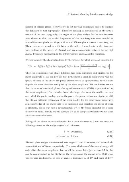
We now consider the shear introduced by the wedges, for which we recall equation 2.3<br />
I(⃗r) = I 0 (⃗r) + I 0 (⃗r + ⃗s) + 2 √ [ ]<br />
φ(⃗r + ⃗s) − φ(⃗r)<br />
I 0 (⃗r) I 0 (⃗r + ⃗s) cos<br />
s + 2πf s<br />
⃗ c · ⃗r ,<br />
where for convenience the phase difference has been multiplied and divided by the<br />
shear amplitude s. We can now see that if the shear is small in comparison with the<br />
spatial changes in the phase, the phase difference can be approximated by the phase<br />
slope in the shear direction multiplied by the shear amplitude. We can further assume<br />
that in terms of measured phase, the signal-to-noise ratio (SNR) is proportional to<br />
the shear amplitude. On the other hand, the larger the shear the smaller the area<br />
over which the pupils overlap, and so the poorer the phase estimation. Again, as with<br />
the tilt, an optimum estimation of the shear needed for the experiment would need<br />
some knowledge of the wavefronts to be measured, and therefore the choice of shear<br />
is arbitrary, and in our case is approximately 5 % of the beam diameter for a beam<br />
diameter of 3 mm. Finally, we will consider 2 % as an acceptable tolerance to the shear<br />
variation across the beam.<br />
Taking all the above in to consideration for a beam diameter of 3 mm, we reach the<br />
following values for the wedge angle δ and thickness:<br />
δ ≈ 10 arcmins, (2.15)<br />
thickness ≈ 0.4 mm, (2.16)<br />
The two glass wedges manufactured have angles 11 and 13 arcmins, and mean thicknesses<br />
0.35 and 0.70 mm respectively. The extra thickness of the second wedge will<br />
only affect the shear amplitude, but as will be shown later (see section 2.7.1), this<br />
can be compensated for by displacing the wedge along the optical axis. Both glass<br />
wedges were produced to be used at angle of incidence α 1 of 45 o and made of BK7,<br />
30


