a new method of calculating the equation of the connecting rod curve
a new method of calculating the equation of the connecting rod curve
a new method of calculating the equation of the connecting rod curve

You also want an ePaper? Increase the reach of your titles
YUMPU automatically turns print PDFs into web optimized ePapers that Google loves.
STRUCTURAL AND KINEMATICAL PROBLEMS OF A LIGHT INDUSTRY MACHINE<br />
MECHANISM<br />
Daniela Cristiana MÎLCOMETE *, Traian PREOTEASA **<br />
*Bondia Tricot SRL Craiova, milcomete@yahoo.com, **CFR Bucureşti<br />
The structural and kinematical analysis <strong>of</strong> a spatial knitting machine mechanism is made. The<br />
mechanism has a seeming family and uses two planar cams, couplings and spatial components. The<br />
kinematical calculation relations are written and results are provided, and <strong>the</strong>n checked<br />
experimentally.<br />
Keywords: Kinematical analyse, spatial trajectory, cam – lugs, motions parasit.<br />
MECHANISM DESCRIPTION<br />
It is well known that very complicated machines, based on mechanical systems, are used in <strong>the</strong> light<br />
industry. Such machines are, more <strong>of</strong>ten than not, built empirically, <strong>the</strong> designers having worked on older<br />
variants, which <strong>the</strong>y have developed. The analysis <strong>of</strong> <strong>the</strong>se machines proved to be difficult and <strong>the</strong> designers<br />
needed solid knowledge <strong>of</strong> <strong>the</strong> technological processes involved.<br />
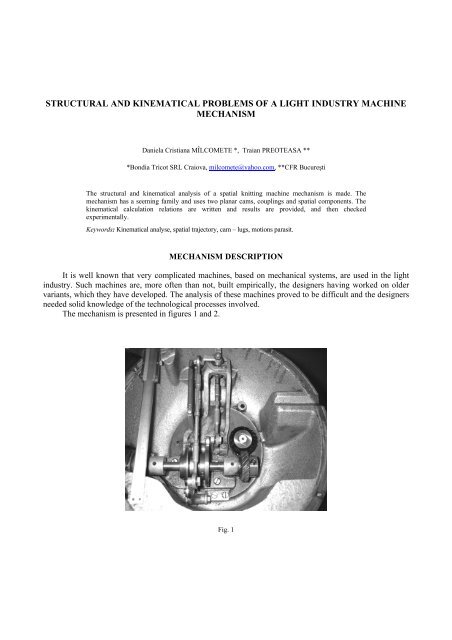
The mechanism is presented in figures 1 and 2.<br />
Fig. 1
Daniela Cristiana MÎLCOMETE , Traian PREOTEASA 244<br />
Fig. 2<br />
As shown, this spatial mechanism is complex indeed. It is designed to displace a “catch member”<br />
observing a number <strong>of</strong> laws so that its point draws <strong>the</strong> trajectory required in <strong>the</strong> technological process.<br />
MECHANISM STRUCTURE<br />
The kinematical mechanism scheme is shown in figure 3.<br />
Fig. 3<br />
The structural solution was found by taking into consideration “seeming families” [Antonescu, 1973].<br />
In respect to this idea, <strong>the</strong> scheme in figure 4 was drawn.
245<br />
Structural and kinematical problems <strong>of</strong> a light industry machine mechanism<br />
The kinematical couplings – structurally parasitical motions being eliminated - are <strong>the</strong> following<br />
(figure 4):<br />
A (0,1) – class V;<br />
G (4,5) – class IV;<br />
B (0, 2) – class V;<br />
H (5,7) – class III;<br />
C (1, 2) – class IV; K (6,0) – class V;<br />
D (2,3) – class IV;<br />
L (3,6) – class III;<br />
E (0,4) – class V; M (6,7) – class V.<br />
F (1,4) – class IV;<br />
Results: n = 7, C5 = 5, C4 = 4, C3 = 2.<br />
Using <strong>the</strong> relation N = c - n, where N is <strong>the</strong> number <strong>of</strong> free outlines, n is <strong>the</strong> number <strong>of</strong> mobile elements and<br />
c – <strong>the</strong> number <strong>of</strong> couplings, we have: N = 11 – 7 = 4, i.e. <strong>the</strong>re are 4 free outlines. Figure 4 shows <strong>the</strong>se<br />
outlines (Roman numerals are used). Looking simultaneously at figures 3 and 4, we conclude that:<br />
- <strong>the</strong> I (AFE) outline has f = 3 and is planar;<br />
- <strong>the</strong> II (ACB) outline has f = 3 and is planar;<br />
- <strong>the</strong> III (BDLK) outline has f = 0 and <strong>the</strong> DL <strong>connecting</strong> <strong>rod</strong> has all motions;<br />
- <strong>the</strong> IV (DLMHGFC) outline has f = 0 and and <strong>the</strong> HM component has all motions.<br />
The seeming family is <strong>the</strong> average <strong>of</strong> real families: f a = (3+3+0+0)/4 = 6/4<br />
The mobility degree is (in our case):<br />
M = (6 – fa) n – (5 – fa) C5 – (4 – fa) C4 – (3 – fa) C3 = ( 6 – 6 / 4) .7 – (5 – 6 / 4).5 – (4 – 6 / 4 ).4 – ( 3 – 6 /<br />
4).2 = 1.<br />
Fig. 4
Daniela Cristiana MÎLCOMETE , Traian PREOTEASA 246<br />
BAR KINEMATICAL MECHANISMS<br />
In <strong>the</strong> kinematical analysis, <strong>the</strong> laws governing <strong>the</strong> two main elements AB and EF are assumed to be<br />
known; it is about motions received from <strong>the</strong> cam shaft.<br />
Experimentally, <strong>the</strong> lengths <strong>of</strong> <strong>the</strong> components and <strong>the</strong> coordinating points attached to <strong>the</strong> base are<br />
determined in relation with <strong>the</strong> system <strong>of</strong> axes originating in E. Therefore, XE, YE, ZE, XA, YA, ZA, XD,<br />
YD, ZD and <strong>the</strong> lengths <strong>of</strong> AB, BC, CD, DH, GH, EF, FG and HM are found.<br />
Applying <strong>the</strong> outline and distance <strong>method</strong>, we have <strong>the</strong> final relation for <strong>the</strong> ABCDH outline:<br />
h sin ϕ+ h cosϕ+ h sin ψ+ h cosψ+ h −2acsin ϕsin ψ= 0 , where:<br />
2 3 4 5 1<br />
2 2 2 2 2<br />
h1 = ( xA − xD) + ( yA − yD) + c + a + ( zA − zD)<br />
−b<br />
2<br />
h2 = 2 a( zA<br />
− zD)<br />
; h3 = 2 a( yA<br />
− yD)<br />
h4 =−2( c zA<br />
− zD)<br />
; h5 = −2( c xA<br />
− xD)<br />
Similarly, for <strong>the</strong> EFGH outline, we write:<br />
e + e sin ψ + e cosψ + e cosϕ + e sin ϕ −2ac cosϕ cosψ −2a h sin ϕ sin ψ = 0 , where:<br />
1 2 1 3 1 4 1 5 1 1 1 1 1 1 9 1 1<br />
e = a + c + h + y + h −b<br />
2<br />
2 2 2 3 2<br />
1 1 1 6 H 7 1<br />
2 = 2 8 6 + 2 7 9 ; e3 = 2c1yH<br />
e4 = − 2a1yH<br />
; e5 = − 2a1h<br />
7<br />
e h h h h<br />
THE CAM-LUG CHAIN KINEMATICS<br />
The pr<strong>of</strong>iles <strong>of</strong> <strong>the</strong> two cams and <strong>the</strong> motion law <strong>of</strong> <strong>the</strong> cam shaft are known in <strong>the</strong> mechanism<br />
analysis. The cam outline <strong>equation</strong>s are determined (in fact <strong>the</strong> <strong>equation</strong>s <strong>of</strong> <strong>the</strong> pr<strong>of</strong>iles equidistant to <strong>the</strong>m<br />
at ray rollers) as polar coordinates – r and θ- and <strong>the</strong>n <strong>the</strong> cam follower inclinations are calculated (fig. 5).<br />
Figure 6 shows <strong>the</strong> oscillatory cam follower, whose point is articulated in B 0 (initially) and <strong>the</strong>n on <strong>the</strong><br />
cam in C.<br />
By applying <strong>the</strong> reverse motion principle, i.e. by ensuring an exterior motion having –ω 1 , <strong>the</strong> cam stops<br />
and <strong>the</strong> cam follower is spinning around <strong>the</strong> cam at –ω 1 in B, B’, etc.<br />
Fig. 5
247<br />
Structural and kinematical problems <strong>of</strong> a light industry machine mechanism<br />
Fig. 6<br />
The cam pr<strong>of</strong>ile <strong>equation</strong> in polar coordinates is r = f (φ). The current angle <strong>of</strong> rotating B is <strong>the</strong> angle γ.<br />
The following relations are written:<br />
h= ( x − x ) + ( y − y )<br />
2 2<br />
BO<br />
A BO<br />
A<br />
x = rcosθ= x + acosϕ<br />
C<br />
yC<br />
= rsin<br />
θ= yB<br />
+ asin<br />
ϕ<br />
x = hcos<br />
γ+ acosϕ<br />
C<br />
B<br />
yC<br />
= hsin<br />
γ+ asin<br />
ϕ<br />
The variable θ value is assigned and r (in <strong>the</strong> <strong>equation</strong> r = f (θ)), XC and YC are calculated. γ is<br />
eliminated from <strong>the</strong> last <strong>equation</strong>s and we have:<br />
2 2 2<br />
( yC<br />
−asin ϕ ) + ( xC<br />
−acos ϕ)<br />
− h = 0<br />
After successive development, we have:<br />
2 2 2 2<br />
( xC + yC + a −h ) −2ayC sinϕ−2axC<br />
cosϕ=<br />
0<br />
φ, i.e. <strong>the</strong> cam follower inclination, is calculated in this <strong>equation</strong>. The cam outline <strong>equation</strong>s are<br />
determined (in fact <strong>the</strong> <strong>equation</strong>s <strong>of</strong> <strong>the</strong> pr<strong>of</strong>iles equidistant to <strong>the</strong>m at ray rollers) as polar coordinates – r<br />
and θ - and <strong>the</strong>n <strong>the</strong> cam follower inclinations are calculated.
Daniela Cristiana MÎLCOMETE , Traian PREOTEASA 248<br />
The mechanism positions are determined by using <strong>the</strong> polynomials φ (t) and φ 1 (t) and by <strong>calculating</strong><br />
<strong>the</strong> time in relation to <strong>the</strong> cam shaft revolution.<br />
The spatial trajectory <strong>of</strong> <strong>the</strong> characteristic point (M) is shown in figure 7, against a remote system <strong>of</strong> axes in<br />
order to have a spatial image.<br />
Fig. 7<br />
CONCLUSIONS<br />
- The mechanism is very complex both structurally and kinematically and different calculations have<br />
been necessary to complete <strong>the</strong> calculation programme.<br />
- The algorithm and <strong>the</strong> mechanism kinematics were proved to be right in comparison with<br />
experimental results;<br />
- The mechanism is not <strong>the</strong> best possible, having parasitic motions and cams which work only part <strong>of</strong><br />
<strong>the</strong> loop; it is obvious that it was designed empirically, on <strong>the</strong> basis <strong>of</strong> previous design and exploitation <strong>of</strong><br />
o<strong>the</strong>r variants;<br />
- The above mentioned algorithm can also be used for real mechanism syn<strong>the</strong>sis.<br />
REFERENCES<br />
1. ANTONESCU, P., Extinderea formulei structurale Dobrovolski la mecanismele complexe de familie aparentǎ, SYROM'73, vol.<br />
B, pg. 1-10.<br />
2. ANTONESCU, P., Sinteza mecanismelor, I.P.B., 1983.<br />
3. PARIKIAN, T.,F. – Multi-generation <strong>of</strong> cupler <strong>curve</strong>s <strong>of</strong> spatial linkages, Mechanism and Machine Theory, 1/1997, pg. 103-110.<br />
4. POPESCU, I., Mecanisme. Noi algoritmi şi programe, Repr. Univ. Craiova, 1997.<br />
5. VOINEA, R., VOICULESCU, D., SIMION, F., P., Int<strong>rod</strong>ucere în mecanica solidului cu aplicaţii în inginerie, Ed. Academiei, 1989.