Barycentric Coordinates for Arbitrary Polygons in the Plane
Barycentric Coordinates for Arbitrary Polygons in the Plane
Barycentric Coordinates for Arbitrary Polygons in the Plane

Create successful ePaper yourself
Turn your PDF publications into a flip-book with our unique Google optimized e-Paper software.
BARYCENTRIC COORDINATES FOR ARBITRARY POLYGONS 15<br />
(a)<br />
(b)<br />
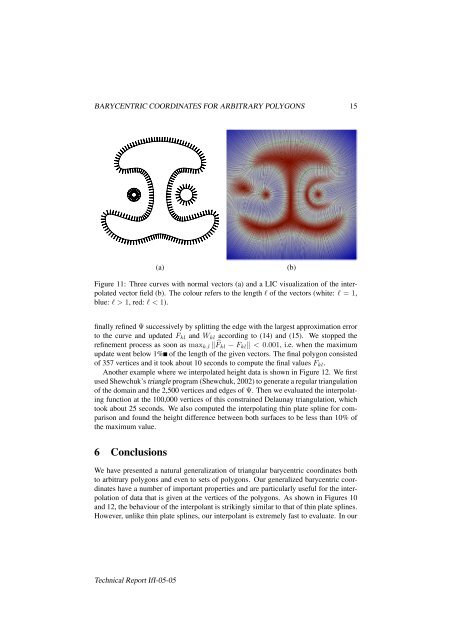
Figure 11: Three curves with normal vectors (a) and a LIC visualization of <strong>the</strong> <strong>in</strong>terpolated<br />
vector field (b). The colour refers to <strong>the</strong> length l of <strong>the</strong> vectors (white: l = 1,<br />
blue: l > 1, red: l < 1).<br />
f<strong>in</strong>ally ref<strong>in</strong>ed Ψ successively by splitt<strong>in</strong>g <strong>the</strong> edge with <strong>the</strong> largest approximation error<br />
to <strong>the</strong> curve and updated F kl and W kl accord<strong>in</strong>g to (14) and (15). We stopped <strong>the</strong><br />
ref<strong>in</strong>ement process as soon as max k,l ‖ ̂F kl − F kl ‖ < 0.001, i.e. when <strong>the</strong> maximum<br />
update went below 1% of <strong>the</strong> length of <strong>the</strong> given vectors. The f<strong>in</strong>al polygon consisted<br />
of 357 vertices and it took about 10 seconds to compute <strong>the</strong> f<strong>in</strong>al values F kl .<br />
Ano<strong>the</strong>r example where we <strong>in</strong>terpolated height data is shown <strong>in</strong> Figure 12. We first<br />
used Shewchuk’s triangle program (Shewchuk, 2002) to generate a regular triangulation<br />
of <strong>the</strong> doma<strong>in</strong> and <strong>the</strong> 2,500 vertices and edges of Ψ. Then we evaluated <strong>the</strong> <strong>in</strong>terpolat<strong>in</strong>g<br />
function at <strong>the</strong> 100,000 vertices of this constra<strong>in</strong>ed Delaunay triangulation, which<br />
took about 25 seconds. We also computed <strong>the</strong> <strong>in</strong>terpolat<strong>in</strong>g th<strong>in</strong> plate spl<strong>in</strong>e <strong>for</strong> comparison<br />
and found <strong>the</strong> height difference between both surfaces to be less than 10% of<br />
<strong>the</strong> maximum value.<br />
6 Conclusions<br />
We have presented a natural generalization of triangular barycentric coord<strong>in</strong>ates both<br />
to arbitrary polygons and even to sets of polygons. Our generalized barycentric coord<strong>in</strong>ates<br />
have a number of important properties and are particularly useful <strong>for</strong> <strong>the</strong> <strong>in</strong>terpolation<br />
of data that is given at <strong>the</strong> vertices of <strong>the</strong> polygons. As shown <strong>in</strong> Figures 10<br />
and 12, <strong>the</strong> behaviour of <strong>the</strong> <strong>in</strong>terpolant is strik<strong>in</strong>gly similar to that of th<strong>in</strong> plate spl<strong>in</strong>es.<br />
However, unlike th<strong>in</strong> plate spl<strong>in</strong>es, our <strong>in</strong>terpolant is extremely fast to evaluate. In our<br />
Technical Report IfI-05-05