C161PI AA / BA-H Step - Infineon
C161PI AA / BA-H Step - Infineon
C161PI AA / BA-H Step - Infineon
You also want an ePaper? Increase the reach of your titles
YUMPU automatically turns print PDFs into web optimized ePapers that Google loves.
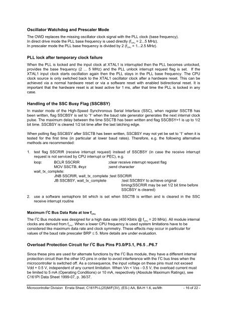
Oscillator Watchdog and Prescaler Mode<br />
The OWD replaces the missing oscillator clock signal with the PLL clock (base frequency).<br />
In direct drive mode the PLL base frequency is used directly (f CPU<br />
= 2...5 MHz).<br />
In prescaler mode the PLL base frequency is divided by 2 (f CPU<br />
= 1...2.5 MHz).<br />
PLL lock after temporary clock failure<br />
When the PLL is locked and the input clock at XTAL1 is interrupted then the PLL becomes unlocked,<br />
provides the base frequency (2 ... 5 MHz) and the PLL unlock interrupt request flag is set. If the<br />
XTAL1 input clock starts oscillation again then the PLL stays in the PLL base frequency. The CPU<br />
clock source is only switched back to the XTAL1 oscillator clock after a hardware reset. This can be<br />
achieved via a normal hardware reset or via a software reset with enabled bidirectional reset. It is<br />
important that the hardware reset is at least active for 1 ms, after that time the PLL is locked in any<br />
case.<br />
Handling of the SSC Busy Flag (SSCBSY)<br />
In master mode of the High-Speed Synchronous Serial Interface (SSC), when register SSCTB has<br />
been written, flag SSCBSY is set to '1' when the baud rate generator generates the next internal clock<br />
pulse. The maximum delay between the time SSCTB has been written and flag SSCBSY=1 is up to 1/2<br />
bit time. SSCBSY is cleared 1/2 bit time after the last latching edge.<br />
When polling flag SSCBSY after SSCTB has been written, SSCBSY may not yet be set to '1' when it is<br />
tested for the first time (in particular at lower baud rates). Therefore, e.g. the following alternative<br />
methods are recommended:<br />
1. test flag SSCRIR (receive interrupt request) instead of SSCBSY (in case the receive interrupt<br />
request is not serviced by CPU interrupt or PEC), e.g.<br />
loop: BCLR SSCRIR ;clear receive interrupt request flag<br />
MOV SSCTB, #xyz<br />
;send character<br />
wait_tx_complete:<br />
JNB SSCRIR, wait_tx_complete ;test SSCRIR<br />
JB SSCBSY, wait_tx_complete<br />
;test SSCBSY to achieve original<br />
timing(SSCRIR may be set 1/2 bit time before<br />
SSCBSY is cleared)<br />
2. use a software semaphore bit which is set when SSCTB is written and is cleared in the SSC<br />
receive interrupt routine<br />
Maximum I 2 C Bus Data Rate at low f CPU<br />
The I 2 C Bus module was designed for a high data rate (400 Kbit/s @ f CPU<br />
= 20 MHz). All module internal<br />
clocks are derived from f CPU<br />
. When a lower CPU frequency is used system limitations have to be<br />
considered like maximum data rate and clock symmetry. These effects may occur in particular for<br />
values of the baud rate prescaler BRP ≤ 5. More details are under evaluation.<br />
Overload Protection Circuit for I 2 C Bus Pins P3.0/P3.1, P6.5 ..P6.7<br />
Since these pins are used for alternate functions by the I 2 C Bus module, they have a different internal<br />
protection circuit than the other I/O pins in order to avoid interference with the I 2 C bus lines when the<br />
microcontroller is switched off. As a consequence, the input voltage on these pins must not exceed<br />
Vdd + 0.5 V, independent of any current limitation. When Vin < Vss - 0.5 V, the overload current must<br />
be limited to 5 mA (Operating Conditions) or 10 mA, respectively (Absolute Maximum Ratings), see<br />
<strong>C161PI</strong> Data Sheet 1999-07, p. 36/37.<br />
Microcontroller Division Errata Sheet, <strong>C161PI</strong>-L(25)M/F(3V), (ES-) <strong>AA</strong>, <strong>BA</strong>-H 1.6, es/Mh - 16 of 22 -


