C161PI AA / BA-H Step - Infineon
C161PI AA / BA-H Step - Infineon
C161PI AA / BA-H Step - Infineon

Create successful ePaper yourself
Turn your PDF publications into a flip-book with our unique Google optimized e-Paper software.
Functional Improvements/Compatibility Aspects<br />
The <strong>C161PI</strong> as the successor of the C161RI provides various technology-based and functional<br />
enhancements:<br />
- Increased operating frequency range<br />
- Reduced power consumption<br />
- Optimized 3 Volt performance<br />
- Clock generation also via on-chip PLL<br />
- Enhanced Power Management with<br />
- Sleep mode (wakeup via external interrupts)<br />
- programmable frequency output signal<br />
- Port output drivers with two selectable edge characteristics<br />
- A/D converter with 10-bit resolution and auto scan/continuous conversion modes<br />
These enhancements are listed in the <strong>C161PI</strong> Specification Update 1998-12 and are included in the<br />
<strong>C161PI</strong> User's Manual V1.0 1999-08.<br />
Most of the changes and improvements are activated only under software control and therefore will be<br />
transparent for existing <strong>C161PI</strong> applications. The following items should be considered in particular<br />
when replacing the C161RI with the <strong>C161PI</strong> in an existing application:<br />
A/D Converter<br />
The conversion result of the 10-bit A/D converter of the <strong>C161PI</strong> is always 10 bits wide and stored in<br />
bitfield ADRES/ADDAT.[9:0]. There is no result positioning option (as it is controlled via bit<br />
ADRP/ADCON.6 in the C161RI), therefore bit ADCON.6 is specified as 'reserved' in the <strong>C161PI</strong>,<br />
i.e. it must not be set to 1. For the <strong>AA</strong>-step of the <strong>C161PI</strong>, it is allowed that bit ADCON.6 = 1 after<br />
execution of instruction EINIT, but not before. The effects on software which was originally written for<br />
the C161RI are as follows:<br />
- when bit ADCON.6 = 0 (default after reset): the 2 LSBs read from ADDAT.[9:0] may be different<br />
from 00b, while on the C161RI, they were always 00b.<br />
- when bit ADCON.6 = 1: the MSB of the result is at position ADDAT.9 in the <strong>C161PI</strong> instead of<br />
ADDAT.7 as in the C161RI, therefore it is no longer possible to directly read the 8 MSBs of the<br />
result from ADDAT with a single byte instruction.<br />
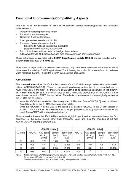
The conversion time of the 10-bit A/D converter is slightly longer than the conversion time of the 8-bit<br />
converter (at the same internal CPU clock frequency fcpu), and also the encoding of bit field<br />
ADCTC/ADCON.[15:14] is different, e.g.<br />
f CPU<br />
[MHz] ADCTC ADC basic<br />
clock f BC<br />
[MHz]<br />
<strong>C161PI</strong> [10-bit]<br />
sample<br />
time t S<br />
[µs]<br />
conversion<br />
time t C 1)<br />
[µs]<br />
ADCTC<br />
C161RI [8-bit]<br />
ADC basic<br />
clock f BC<br />
[MHz]<br />
sample<br />
time t S<br />
[µs]<br />
conversion<br />
time t C<br />
[µs]<br />
25 00b 6.25 1.28 7.8 - 2) - - -<br />
16 00b 4.0 2.0 12.125 01b 4.0 1.5 7.625<br />
12 00b 3.0 2.66 16.166 01b 3.0 2.0 10.166<br />
12 01b 6.0 1.33 8.083 00b - 3) - -<br />
notes: 1) sample time on <strong>C161PI</strong> is programmable, calculation here with shortest option (ADCON.[13:12] = 00b, t S<br />
= 8 t BC<br />
)<br />
2) operation at 25 MHz f CPU<br />
not specified for C161RI<br />
3) setting would result in 6 MHz ADC basic clock f BC<br />
, not specified for C161RI<br />
Microcontroller Division Errata Sheet, <strong>C161PI</strong>-L(25)M/F(3V), (ES-) <strong>AA</strong>, <strong>BA</strong>-H 1.6, es/Mh - 20 of 22 -