C161PI AA / BA-H Step - Infineon
C161PI AA / BA-H Step - Infineon
C161PI AA / BA-H Step - Infineon

You also want an ePaper? Increase the reach of your titles
YUMPU automatically turns print PDFs into web optimized ePapers that Google loves.
Clock System<br />
The oscillator circuit which is implemented in the <strong>C161PI</strong> and the C161RI is optimized for low power<br />
consumption. Its recommended input frequency range for operation with a crystal is 4 .. 16 MHz. In<br />
order to obtain internal CPU frequencies beyond this range, the PLL or an external oscillator should be<br />
used. The internal oscillator circuit is compatible to Type LP_2 as described in the Application Note<br />
AP2420 (’Crystal Oscillator of the C500 and C166 Microcontroller Families’). When a crystal is used, it<br />
is advised to follow the recommendations for the size of the external capacitors of the oscillator circuit,<br />
and to check the safety factor of the oscillator circuit.<br />
The Application Note with detailed information on all oscillator types is available on the <strong>Infineon</strong><br />
Microcontroller Application Note page on<br />
http://www.infineon.com/cgi/ecrm.dll/ecrm/scripts/prod_cat.jsp?oid=-8137<br />
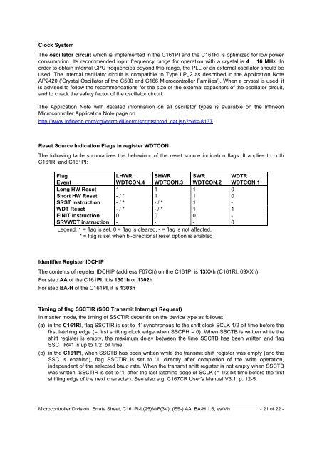
Reset Source Indication Flags in register WDTCON<br />
The following table summarizes the behaviour of the reset source indication flags. It applies to both<br />
C161RI and <strong>C161PI</strong>:<br />
Flag<br />
Event<br />
LHWR<br />
WDTCON.4<br />
SHWR<br />
WDTCON.3<br />
SWR<br />
WDTCON.2<br />
WDTR<br />
WDTCON.1<br />
Long HW Reset 1 1 1 0<br />
Short HW Reset - / * 1 1 0<br />
SRST instruction - / * - / * 1 -<br />
WDT Reset - / * - / * 1 1<br />
EINIT instruction 0 0 0 -<br />
SRVWDT instruction - - - 0<br />
Legend: 1 = flag is set, 0 = flag is cleared, - = flag is not affected,<br />
* = flag is set when bi-directional reset option is enabled<br />
Identifier Register IDCHIP<br />
The contents of register IDCHIP (address F07Ch) on the <strong>C161PI</strong> is 13XXh (C161RI: 09XXh).<br />
For step <strong>AA</strong> of the <strong>C161PI</strong>, it is 1301h or 1302h<br />
For step <strong>BA</strong>-H of the <strong>C161PI</strong>, it is 1303h<br />
Timing of flag SSCTIR (SSC Transmit Interrupt Request)<br />
In master mode, the timing of SSCTIR depends on the device type as follows:<br />
(a) in the C161RI, flag SSCTIR is set to ‘1’ synchronous to the shift clock SCLK 1/2 bit time before the<br />
first latching edge (= first shifting clock edge when SSCPH = 0). When SSCTB is written while the<br />
shift register is empty, the maximum delay between the time SSCTB has been written and flag<br />
SSCTIR=1 is up to 1/2 bit time.<br />
(b) in the <strong>C161PI</strong>, when SSCTB has been written while the transmit shift register was empty (and the<br />
SSC is enabled), flag SSCTIR is set to ‘1’ directly after completion of the write operation,<br />
independent of the selected baud rate. When the transmit shift register is not empty when SSCTB<br />
was written, SSCTIR is set to '1' after the last latching edge of SCLK (= 1/2 bit time before the first<br />
shifting edge of the next character). See also e.g. C167CR User's Manual V3.1, p. 12-5.<br />
Microcontroller Division Errata Sheet, <strong>C161PI</strong>-L(25)M/F(3V), (ES-) <strong>AA</strong>, <strong>BA</strong>-H 1.6, es/Mh - 21 of 22 -