Kinwald Edition XXX - Team Losi Racing
Kinwald Edition XXX - Team Losi Racing
Kinwald Edition XXX - Team Losi Racing

You also want an ePaper? Increase the reach of your titles
YUMPU automatically turns print PDFs into web optimized ePapers that Google loves.
TOOLS REQUIRED<br />
<strong>Team</strong> <strong>Losi</strong> has supplied all necessary Allen wrenches and a special wrench that is needed for assembly and adjustments. The following<br />
common tools will also be required: Needle-nose pliers, regular pliers, hobby knife, scissors or other body cutting/trimming tools, and<br />
a soldering iron may be necessary for radio installation. 3/16", 1/4", 11/32", and 3/8" nut drivers are optional.<br />
RADIO/ELECTRICAL<br />
A suggested radio layout is provided in this manual. Your high-performance R/C center should be consulted regarding specific<br />
questions pertaining to radio/electrical equipment.<br />
HARDWARE IDENTIFICATION<br />
When in question, use the hardware identification guide in each step. For screws, the prefix number designates the screw size and<br />
number of threads per inch (i.e., 4-40 is #4 screw with 40 threads per inch). The second number or fraction designates the length of<br />
the screw. For cap-head and button-head screws, this number refers to the length of the threaded portion of the screw. For flat-head<br />
screws, this number refers to the overall length of the screw. Bearings and bushings are referenced by the inside diameter x outside<br />
diameter. Shafts and pins are referred to by diameter x length. Washers are described by inside diameter or the screw size that will<br />
pass through the inside diameter. E-clips are sized by the shaft diameter that they attach to.<br />
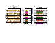
MOTORS AND GEARING<br />
The Triple-X includes an 78-tooth, 48-pitch spur gear. The overall internal drive ratio of the transmission is 2.43:1. The pinion gear that<br />
is used will determine the final drive ratio. To calculate the final drive ratio, first divide the spur gear size by the pinion gear size. For<br />
example, if you are using a 20-tooth pinion gear, you would divide 78 (spur gear size) by 20 (pinion gear size). 78/20=3.9. This tells<br />
you that 3.9 is the external drive ratio. Next, multiply the internal drive ratio (2.43) by the external drive ratio (in this case 3.9).<br />
2.43 x 3.9 = 9.477. This means that by using a 20-tooth pinion gear with the standard 78-tooth spur gear, the final drive ratio is 9.477.<br />
Consult your high-performance shop for recommendations to suit your racing style and class. The chart below lists some of the<br />
more common motor types and a recommended initial gearing for that motor. Ratios can be adjusted depending on various track<br />
layouts, tire sizes, and battery types.<br />
RECOMMENDED INITIAL GEARING FOR COMMON MOTORS<br />
TYPE OF MOTOR PINION SPUR<br />
24 o Stock 23 78<br />
11-Turn Modified 19 78<br />
12-Turn Modified 20 78<br />
13-Turn Modified 21 78<br />
14-Turn Modified 22 78<br />
15-Turn Modified 23 78<br />
16-Turn Modified 24 78<br />
17-Turn Modified 25 78<br />
TABLE OF CONTENTS<br />
1. INTRODUCTION ............................................................i<br />
Completed Kit Dimensions ........................................... i<br />
Notes & Symbols ......................................................... i<br />
Kit Manual Organization ............................................... i<br />
Important Safety Notes ................................................ i<br />
Tools Required ............................................................ ii<br />
Radio/Electrical ........................................................... ii<br />
Hardware Identification ............................................... ii<br />
Recommended Gearing .............................................. ii<br />
2. BAG A ....................................................................... 1-2<br />
3. BAG B ....................................................................... 3-7<br />
4. BAG C ..................................................................... 8-11<br />
5. BAG D ................................................................... 12-19<br />
6. BAG E ................................................................... 20-23<br />
7. BAG F ......................................................................... 24<br />
8. BAG G ................................................................... 25-30<br />
9. Checklist Before Your First Run ................................31<br />
10. Tips From the <strong>Team</strong> ............................................. 31-33<br />
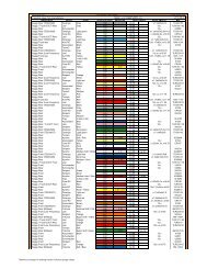
11. Spare Parts List ................................................... 34-36<br />
<strong>Team</strong> <strong>Losi</strong> is continually changing and improving designs; therefore, the actual part may appear slightly different than the illustrated part. Illustrations of parts and assemblies may be<br />
slightly distorted to enhance pertinent details.<br />
ii